Remove rear SKODA SUPERB 2016 3.G / (B8/3V) Owner's Guide
[x] Cancel search | Manufacturer: SKODA, Model Year: 2016, Model line: SUPERB, Model: SKODA SUPERB 2016 3.G / (B8/3V)Pages: 336, PDF Size: 53.89 MB
Page 296 of 336

CAUTIONMake sure when lifting not to damage cover parts by the screwdriver in the
shift lever environment.
Replacing windscreen wiper blades
Introduction
This chapter contains information on the following subjects:
Replacing the windscreen wiper blades
294
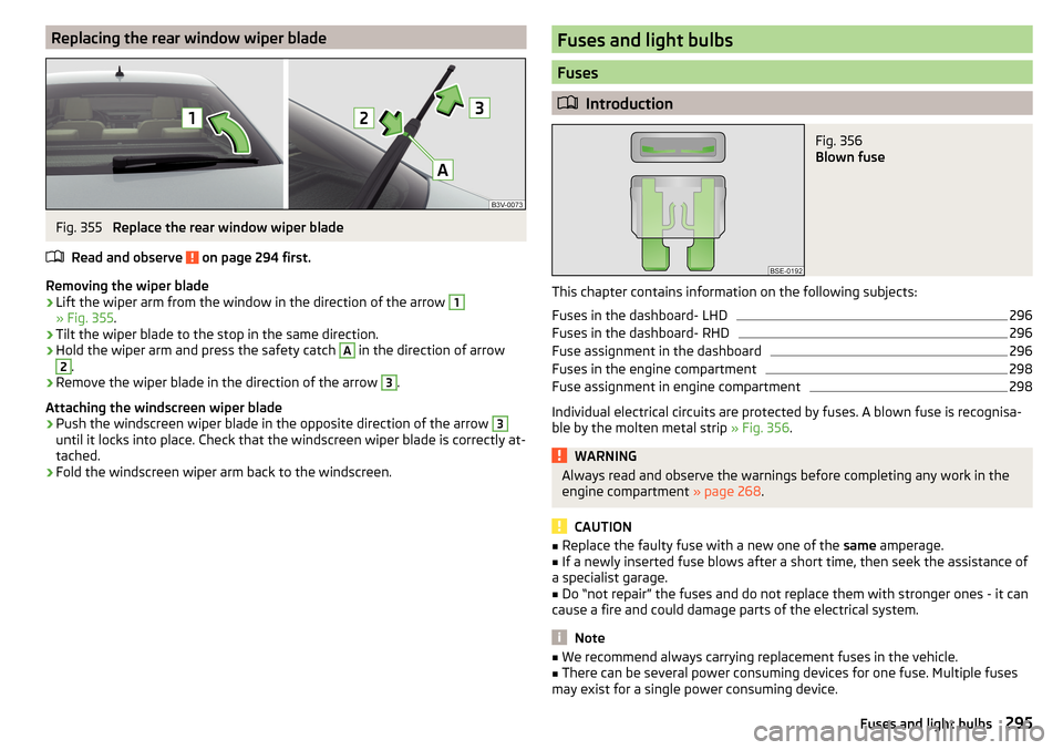
Replacing the rear window wiper blade
295WARNINGReplace the windscreen wiper blades once or twice a year for safety rea-
sons.
Replacing the windscreen wiper blades
Fig. 353
Setting the service position for
the wiper arms
Fig. 354
Replace windscreen wiper blade
Read and observe on page 294 first.
Before replacing the windscreen wiper blade, put the windscreen wiper arms
into the service position.
Setting the service position
›
Switch the ignition on and off again.
›
Within 10 seconds, push the lever in the direction of arrow » Fig. 353 and
hold for approximately 2 seconds.
Removing the wiper blade
›
Lift the wiper arm from the window in the direction of the arrow
1
» Fig. 354 .
›
Tilt the wiper blade to the stop in the same direction.
›
Hold the wiper arm and press the safety catch
A
in the direction of arrow
2
.
›
Remove the wiper blade in the direction of the arrow
3
.
Attaching the windscreen wiper blade
›
Push the windscreen wiper blade in the opposite direction of the arrow
3
until it locks into place. Check that the windscreen wiper blade is correctly at-
tached.
›
Fold the windscreen wiper arm back to the windscreen.
›
Turn on the ignition and press the lever into the direction of the arrow
» Fig. 353 .
Move the windscreen wiper arms into the home position.
294Do-it-yourself
Page 297 of 336

Replacing the rear window wiper bladeFig. 355
Replace the rear window wiper blade
Read and observe
on page 294 first.
Removing the wiper blade
›
Lift the wiper arm from the window in the direction of the arrow
1
» Fig. 355 .
›
Tilt the wiper blade to the stop in the same direction.
›
Hold the wiper arm and press the safety catch
A
in the direction of arrow
2
.
›
Remove the wiper blade in the direction of the arrow
3
.
Attaching the windscreen wiper blade
›
Push the windscreen wiper blade in the opposite direction of the arrow
3
until it locks into place. Check that the windscreen wiper blade is correctly at-
tached.
›
Fold the windscreen wiper arm back to the windscreen.
Fuses and light bulbs
Fuses
Introduction
Fig. 356
Blown fuse
This chapter contains information on the following subjects:
Fuses in the dashboard- LHD
296
Fuses in the dashboard- RHD
296
Fuse assignment in the dashboard
296
Fuses in the engine compartment
298
Fuse assignment in engine compartment
298
Individual electrical circuits are protected by fuses. A blown fuse is recognisa-
ble by the molten metal strip » Fig. 356.
WARNINGAlways read and observe the warnings before completing any work in the
engine compartment » page 268.
CAUTION
■
Replace the faulty fuse with a new one of the same amperage.■If a newly inserted fuse blows after a short time, then seek the assistance of
a specialist garage.■
Do “not repair” the fuses and do not replace them with stronger ones - it can
cause a fire and could damage parts of the electrical system.
Note
■ We recommend always carrying replacement fuses in the vehicle.■There can be several power consuming devices for one fuse. Multiple fuses
may exist for a single power consuming device.295Fuses and light bulbs
Page 300 of 336

No.Consumer47Rear window wiper48Blind spot detection49Engine starting, clutch pedal switch50Opening the boot lid51Heating of the rear seats52Heated front seats53Heated rear windowA
» Fig. 359Multifunctional unit for taxi vehicles - LHD
B
» Fig. 36 0Multifunctional unit for taxi vehicles - RHD
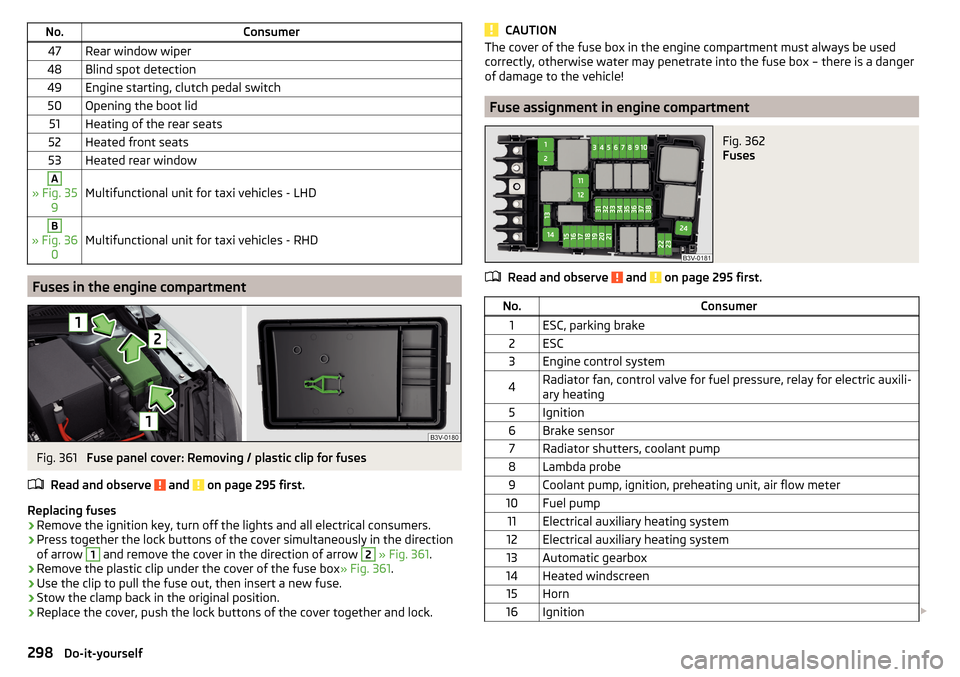
Fuses in the engine compartment
Fig. 361
Fuse panel cover: Removing / plastic clip for fuses
Read and observe
and on page 295 first.
Replacing fuses
›
Remove the ignition key, turn off the lights and all electrical consumers.
›
Press together the lock buttons of the cover simultaneously in the direction
of arrow
1
and remove the cover in the direction of arrow
2
» Fig. 361 .
›
Remove the plastic clip under the cover of the fuse box » Fig. 361.
›
Use the clip to pull the fuse out, then insert a new fuse.
›
Stow the clamp back in the original position.
›
Replace the cover, push the lock buttons of the cover together and lock.
CAUTIONThe cover of the fuse box in the engine compartment must always be used
correctly, otherwise water may penetrate into the fuse box – there is a danger
of damage to the vehicle!
Fuse assignment in engine compartment
Fig. 362
Fuses
Read and observe and on page 295 first.
No.Consumer1ESC, parking brake2ESC3Engine control system4Radiator fan, control valve for fuel pressure, relay for electric auxili-
ary heating5Ignition6Brake sensor7Radiator shutters, coolant pump8Lambda probe9Coolant pump, ignition, preheating unit, air flow meter10Fuel pump11Electrical auxiliary heating system12Electrical auxiliary heating system13Automatic gearbox14Heated windscreen15Horn16Ignition 298Do-it-yourself
Page 304 of 336

Fitting›Slide the plug in the opposite direction of the arrow 4» Fig. 367 into the
light. The locks on the plug must be inserted securely.›
Insert the light with the openings
D
onto the studs
C
in the body and care-
fully press in the light » .
›
Screw the tail lamp into place and install the cover. The cover must engage
securely.
CAUTION
■ Ensure that when re-inserting the light the wiring harness between the body
and the light is not jammed and the seal C » Fig. 368 on page 302 is correctly
inserted - Otherwise there is a risk of water ingress and damage to the electri-
cal installation.■
Ensure that the vehicle paintwork and the tail lamp are not damaged when
removing and installing the lamp.
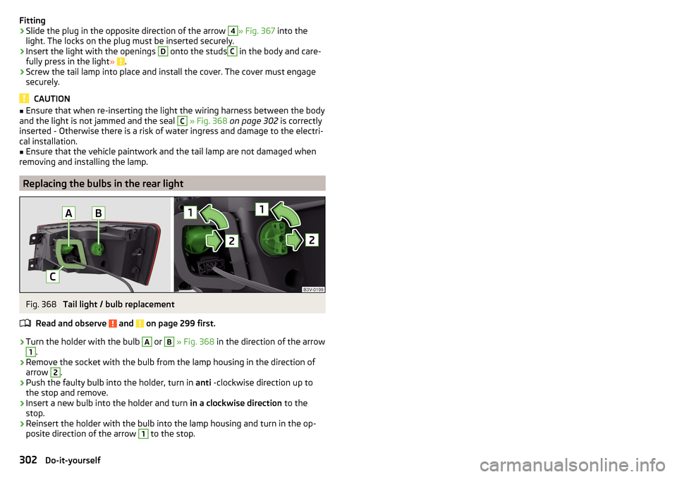
Replacing the bulbs in the rear light
Fig. 368
Tail light / bulb replacement
Read and observe
and on page 299 first.
›
Turn the holder with the bulb
A
or
B
» Fig. 368 in the direction of the arrow
1
.
›
Remove the socket with the bulb from the lamp housing in the direction of
arrow
2
.
›
Push the faulty bulb into the holder, turn in anti -clockwise direction up to
the stop and remove.
›
Insert a new bulb into the holder and turn in a clockwise direction to the
stop.
›
Reinsert the holder with the bulb into the lamp housing and turn in the op-
posite direction of the arrow
1
to the stop.
302Do-it-yourself