Remove rear SKODA SUPERB 2016 3.G / (B8/3V) Owner's Guide
[x] Cancel search | Manufacturer: SKODA, Model Year: 2016, Model line: SUPERB, Model: SKODA SUPERB 2016 3.G / (B8/3V)Pages: 336, PDF Size: 53.89 MB
Page 108 of 336

When opening the boot lid with the function activated, the roll-up cover auto-
matic rolls-up of the intermediate position B » Fig. 128 on page 105 .
Activation/deactivation can be carried out in Infotainment in the menu
→
→
Opening and closing
.
Note
The setting (activation/deactivation) of the automatic rolling up is stored (de-
pending on the Infotainment type) in the active user account personalisation
» page 49 .
Side storage compartment and trays
Fig. 130
Side shelf removal / open side pocket
Read and observe
and on page 101 first.
Located at the two sides of the luggage compartment, depending on vehicle equipment are side trays » Fig. 130 -
or lockable side compartments
» Fig. 130 -
.
The space behind the tray and in the tray is provided for storing small objects
up to a total weight of 2.5 kg.
Side compartment
›
Remove the storage compartment cover in the direction of the ar-
row » Fig. 130 -
.
To insert , proceed in reverse order.
Side compartment
›
To open , pull the handle in direction of arrow
1
and open the compartment
in the direction of arrow
2
» Fig. 130
. The tray can be removed.
›
To close , swivel the compartment against the direction of arrow
2
.
Cargo elementFig. 131
Pull out Cargo elements: Variant 1 / Variant 2
Fig. 132
Pull out Cargo elements: Variant 3 / Load fastening example
Read and observe
and on page 101 first.
The cargo elements are designed for mounting and securing loads with a max- imum gross weight of 8 kg.
›
Before use, remove the Cargo elements in the direction of the arrows
» Fig. 131 and» Fig. 132 -
.
›
Use the cargo elements to secure the load as close as possible to the rear
seats » Fig. 132
.
›
After use, stow the Cargoelements in their original position.
106Using the system
Page 110 of 336

Multi-function pocketFig. 135
Multi-function pocket: Pull out / insert / push in / remove
Fig. 136
Remove the left side cover / store multifunction tray
Read and observe
and on page 101 first.
The multifunction pocket (following as pocket) is provided for the storage of
clothing and light objects with no sharp edges.
The maximum permissible load of the multifunction box is 3 kg.
Removal and fitting›Fold down the front hooks on both sides of the luggage compartment in the
direction of arrow 1
» Fig. 135 .
›
Grasp the rear bar
A
with both hands and withdraw the pocket in arrow di-
rection
2
.
›
Place the rear bar onto the two hooks that are folded forward in the direc-
tion of the arrow
3
all the way to the stop.
Pushing in
›
Remove the rear bar of the hook in direction of arrow
4
push in the pocket
in the direction of arrow
5
» Fig. 135 .
›
Place the rear bar against the front bar and press them together at both
ends
B
.
›
The front hooks on both sides of the luggage compartment fold back oppo-
site to the direction of arrow
1
.
Removing/inserting
›
Remove the roll-up luggage compartment cover » page 105.
›
Remove the pocket from the fittings in the direction of the arrow
6
» Fig. 135.
Insertion takes place in reverse order.
›
Insert the end of the bar marked
in the right-hand mounting, and the end
marked
in the left-hand mounting. The arrows should be pointing forward.
Stowage
If the vehicle is equipped with the variable loading floor, then the removable
pocket cover can be stowed in the recesses of the luggage compartment side
trim.
›
Fold the variable loading floor into the upper position » page 110.
›
Open the side trays on both sides of the luggage compartment » Fig. 130 on
page 106 -
.
›
Remove the left side cover in the arrow direction
1
» Fig. 136 .
›
Insert the pocket in the recesses of the side trim in the arrow direction
2
and stow in the direction of arrow
3
.
›
Reinsert the left side cover in the opposite direction to the arrow
1
.
›
Close the side compartments on both sides of the luggage compartment.
›
Fold out the variable loading floor to the upper position.
Note
If you want to stow the roll-up luggage compartment cover and the multifunc-
tion pocket at the same time , then it is necessary that the rear part of the roll-
up luggage compartment covers the multifunction pocket.108Using the system
Page 111 of 336
Removable lightFig. 137
Removable lamp
Fig. 138
Removable light: Removing / inserting
Read and observe
and on page 101 first.
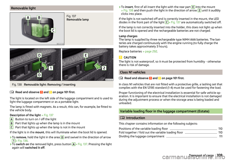
The light is located on the left side of the luggage compartment and is used to light the luggage compartment or as a portable light.
The lamp is fitted with magnets. As a result, this can, for example, be fitted to
the vehicle body.
Description of the light » Fig. 137
Button to turn on / off the light
Part that lights up when the lamp is in the mount
Part that lights up when the lamp is not in the mount
If the light is in the mount, this will illuminate when the boot lid is opened.
›
To remove , hold the light in the area
D
and swivel in the direction of arrow
1
» Fig. 138 .
›
To switch on the removed light, press button
A
» Fig. 137. Pressing the light
again will switched it off .
ABC›To
insert , first of all insert the light with the rear part E into the mount
» Fig. 138 and then push the light in the direction of arrow 2 until it audibly
clicks into place.
If the light is not switched off and is correctly inserted in the mount, the LED diodes in the front part of the light C
» Fig. 137 are automatically switched off.
If the lamp is not correctly inserted into the holder, this does not light up when
the boot lid is opened and the rechargeable batteries are not charged.
Lamp charges
The lamp is supplied by three rechargeable type NiMH AAA batteries. The bat-
teries are charged continuously with the engine running (to fully charge the
battery takes approximately 3 hours).
Replace batteries » page 292.
CAUTION
The light is not waterproof, so it must be protected from humidity - otherwise
there is risk of damage.
Class N1 vehicles
Read and observe
and on page 101 first.
In class N1 vehicles that are not fitted with a protective grille, a lashing set that
complies with the EN 12195 standard (1-4) must be used for fastening the load.
Proper functioning of the electrical installation is essential for safe vehicle op-
eration. It is important to ensure that the electrical installation is not damaged
during the adjustment process or when the storage area is being loaded and
unloaded.
Variable loading floor in the luggage compartment (Estate)
Introduction
This chapter contains information on the following subjects:
Positions of the variable loading floor
110
Fold together / fold out the variable loading floor
110
Dividing the luggage compartment
111109Transport of cargo
Page 114 of 336
›Make sure that the crossbar is firmly seated in the two mountings D.›Fold back part A of the roll-up luggage compartment cover in the opposite
direction of the arrow » Fig. 143.
Using the net partition behind the rear seats›
Fold out part
A
of the roll-up luggage compartment cover in the direction of
arrow » Fig. 143 .
›
First pull the crossbar back slightly on the one side and then on the other
side and remove it from the mountings
D
» Fig. 144 .
›
Hold the crossbar
C
in such a way that the net partition can slowly roll up
without being damaged.
›
Fold back part
A
of the roll-up luggage compartment cover in the opposite
direction of the arrow » Fig. 143.
Pull out and secure the net partition behind the front seats
The process is analogous to that for behind the rear seats. Before removing
the net partition, the rear seat backrests should be folded forwards. After roll-
ing up the net partition in the housing, the rear seat backrests should then be
folded back » page 83.
CAUTION
If the net partition blocks when pulling it out, push the release lever B in the
direction of the arrow » Fig. 143.
Removing and installing the net partition housing
Fig. 145
Removing the net partition
housing
›
To remove , fold forwarded the rear seat backrests and open the rear right
door.
›
Push the housing
A
in the direction of the arrow
1
and remove it from the
mountings in the direction of the arrow
2
» Fig. 145 .
›
To install , insert the recesses on the housing
A
into the mountings on the
rear seat backrests and push the housing against the arrow
1
up to the
stop.
› Fold the rear seat backrests to their original position.
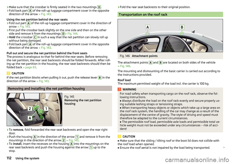
Transportation on the roof rack
Fig. 146
Attachment points
The attachment points
A
and
B
are located on both sides of the vehicle
» Fig. 146 .
The mounting and dismounting of the basic carrier is carried out according to
the instructions provided.
Roof load
The maximum permitted weight of the load incl. the carrier is 100 kg.
WARNINGFor road safety when transporting cargo on the roof rack, observe the fol-
lowing instructions.■
Always distribute the load on the roof rack evenly and secure properly us-
ing suitable lashing straps or tensioning straps.
■
When transporting heavy objects or objects which take up a large area on
the roof rack system, the handling of the car may change as a result of the
displacement of the centre of gravity. The style of driving and speed must
therefore be adapted to the current circumstances.
■
The permissible roof load, permissible axle loads and permissible total ve-
hicle weight must not be exceeded under any circumstances – risk of acci-
dent!
CAUTION
■ Make sure that the sliding / tilting roof or the boot lid does not collide with
the roof load when opened.■
Ensure the roof aerial is not impaired by the load being transported.
112Using the system
Page 221 of 336
WARNINGThe general information relating to the use of assistance systems must be
observed » page 212, in section Introduction .WARNING■
In the case of a collision or damage to the rear of the vehicle, the function
of the systems may be affected - risk of accident! Have the vehicle checked
by a specialist garage.■
Do not cover the sensor area - the function of the systems could be limi-
ted. ■ Remove snow, ice and such obstacles from the sensor environment im-
mediately.
WARNINGThe wizard for “blind spot”monitoring is limited by physical and system-re-
lated limits. Therefore, in the following situations the system can be de-
layed in drawing attention (or not at all) to a vehicle in the next land.■
When a vehicle is approaching at a very high speed.
■
When passing through a very sharp curve or a roundabout.
CAUTION
■ If a trailer or other accessory is to be connected to the trailer socket, then
the two systems are not available.■
In adverse weather conditions (heavy rain, water vapour, very low or high
temperatures, etc.), the system function may be limited - “failure to recognise
a vehicle”.
■
Accessories additionally installed on the vehicle rear, such as bicycle carriers,
can impair the system function.
Rear Traffic Alert- OperationFig. 272
Infotainment screen: Warning indicator / driving situation
Read and observe
and on page 219 first.
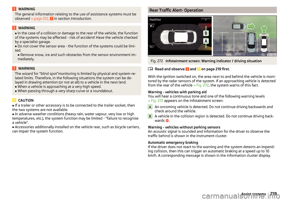
With the ignition switched on, the area next to and behind the vehicle is moni-
tored by the radar sensors of the system. If an approaching vehicle is detected
from the rear of the vehicle » Fig. 272, the system warns of this fact.
Warning - vehicles with parking aid
You will hear a continuous tone and one of the following warning levels
» Fig. 272 appears on the Infotainment screen.
An oncoming vehicle is detected. Do not continue driving backwards and
check around the vehicle.
A vehicle in the collision region is detected. Do not continue driving back-
wards .
Warning - vehicles without parking sensors
An acoustic signal is sounded and information for the driver to observe the
traffic behind is shown in the instrument cluster.
Automatic emergency braking
If the driver does not react to the warning and the system detects an impend-
ing collision, then this can trigger an automatic braking at a speed up to 10
km/h. A corresponding message is shown in the information cluster display.
AB219Assist systems
Page 223 of 336
NoteThe brightness of the indicator light is dependent on the setting of the ve-
hicle lighting. With the low or high beam on the brightness of the light will be
lower.
Activation / deactivation
Read and observe
and on page 219 first.
The activation or deactivation of the system can be carried out in one of the
following ways. ▶ In the instrument cluster display » page 48, Menu item
Assist systems
.
▶ In Infotainment in the menu
→
→
Driver assistance
(Applies to the wizard
for “Blind Spot” Monitoring).
▶ In Infotainment in the
menu
→
→
Parking and manoeuvring
(Applies to
Rear Traffic Alerts).
After switching off and switching on the ignition, depending on the setting pri-
or to switching off the ignition, the systems remains activated / deactivated.
Note
When activating the wizard for “blind spot” monitoring, the warning lights
illuminate briefly in the two exterior mirrors.
Malfunctions
Read and observe
and on page 219 first.
If the systems are not available for some unknown reason, an appropriate
message appears in the display of the instrument cluster.
Sensor covered / dirty
If the sensor is dirty or covered, a message indicating that there is no sensor
view appears. Clean or remove the obstructing object from the sensor environ-
ment » Fig. 271 on page 218 .
Systems unavailable
If the systems are currently unavailable, a message regarding the unavailability
appears. Stop the vehicle, switch off the engine and then start it again. If the
systems are still not available, seek the assistance of a specialist garage.
System fault
In the case of a system fault, an error message appears. Seek help from a spe-
cialist garage.
Reversing camera
Introduction
This chapter contains information on the following subjects:
Operation
222
Activation / deactivation
222
Function surfaces
223
Orientation lines and roadway
223
Mode - Lateral Parking
224
Mode - Parallel parking
224
mode- Driving up to a trailer / Distance monitoring
225
Mode - Monitoring the area behind the vehicle
225
The rear view camera (following as system) helps the driver when parking and
manoeuvring by displaying the area behind the vehicle in the Infotainment
screen (hereinafter only referred to as screen).
There are four modes available for different situations during the park and ma- noeuvring action. The mode change is carried out using the function surfaces
on the screen » page 223.
WARNING■
The general information relating to the use of assistance systems must
be observed » page 212, in section Introduction .■
The system detects obstacles. The display of the auxiliary boxes and lines
is independent of the actual vehicle environment. The driver must judge for
themselves whether the vehicle can park safely in the selected parking
space.
■
The camera may not be soiled or obscured, otherwise the system function
will be significantly affected - there is a risk of accident. For information on
cleaning » page 261 .
221Assist systems
Page 283 of 336
It is possible to store the reflective vests for the passengers on the rear seat in
the storage compartment in the rear doors.
Fire extinguisher
Fig. 330
Release the fire extinguisher
The fire extinguisher is attached by two straps in a bracket under the front
passenger's seat.
›
To remove the fire extinguisher, release the safety catches on the two belts
in the direction of arrow » Fig. 330and remove the fire extinguisher.
›
To secure , place the fire extinguisher back in the mount and secure with the
belts.
The Owner´s Manual is fitted next to the fire extinguisher.
Pay attention to the expiration date of the fire extinguisher. After this date,
the correct function of the device is not guaranteed.
WARNINGAlways properly secure the fire extinguisher, there is a risk of injury in the
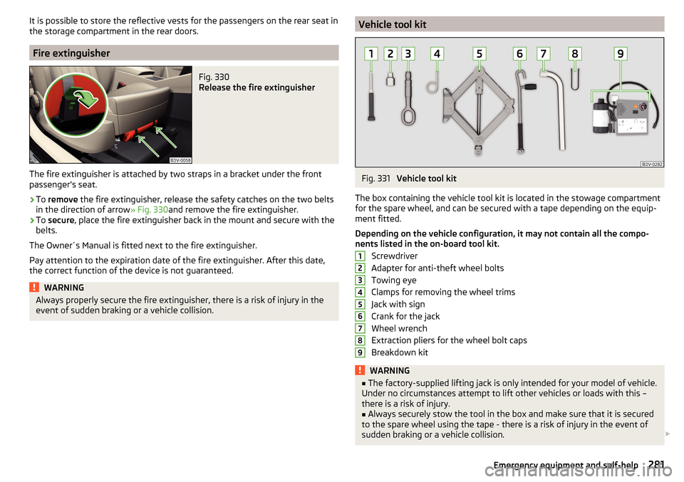
event of sudden braking or a vehicle collision.Vehicle tool kitFig. 331
Vehicle tool kit
The box containing the vehicle tool kit is located in the stowage compartment for the spare wheel, and can be secured with a tape depending on the equip-
ment fitted.
Depending on the vehicle configuration, it may not contain all the compo-
nents listed in the on-board tool kit.
Screwdriver
Adapter for anti-theft wheel bolts
Towing eye
Clamps for removing the wheel trims
Jack with sign
Crank for the jack
Wheel wrench
Extraction pliers for the wheel bolt caps
Breakdown kit
WARNING■ The factory-supplied lifting jack is only intended for your model of vehicle.
Under no circumstances attempt to lift other vehicles or loads with this –
there is a risk of injury.■
Always securely stow the tool in the box and make sure that it is secured
to the spare wheel using the tape - there is a risk of injury in the event of
sudden braking or a vehicle collision.
123456789281Emergency equipment and self-help
Page 290 of 336
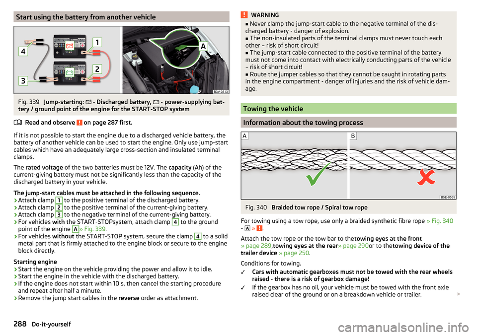
Start using the battery from another vehicleFig. 339
Jump-starting:
- Discharged battery,
- power-supplying bat-
tery / ground point of the engine for the START-STOP system
Read and observe
on page 287 first.
If it is not possible to start the engine due to a discharged vehicle battery, the
battery of another vehicle can be used to start the engine. Only use jump-start
cables which have an adequately large cross-section and insulated terminal
clamps.
The rated voltage of the two batteries must be 12V. The capacity (Ah) of the
current-giving battery must not be significantly less than the capacity of the
discharged battery in your vehicle.
The jump-start cables must be attached in the following sequence.
›
Attach clamp
1
to the positive terminal of the discharged battery.
›
Attach clamp
2
to the positive terminal of the current-giving battery.
›
Attach clamp
3
to the negative terminal of the current-giving battery.
›
For vehicles with the START-STOPsystem, attach clamp
4
to the ground
point of the engine
A
» Fig. 339 .
›
For vehicles without the START-STOP system, secure the clamp
4
to a solid
metal part that is firmly attached to the engine block or secure to the engine
block directly.
Starting engine
›
Start the engine on the vehicle providing the power and allow it to idle.
›
Start the engine in the vehicle with the discharged battery.
›
If the engine does not start within 10 s, then cancel the starting procedure
and repeat after half a minute.
›
Remove the jump start cables in the reverse order as attachment.
WARNING■
Never clamp the jump-start cable to the negative terminal of the dis-
charged battery - danger of explosion.■
The non-insulated parts of the terminal clamps must never touch each
other – risk of short circuit!
■
The jump-start cable connected to the positive terminal of the battery
must not come into contact with electrically conducting parts of the vehicle
– risk of short circuit!
■
Route the jumper cables so that they cannot be caught in rotating parts
in the engine compartment - danger of injuries and the risk of vehicle dam-
age.
Towing the vehicle
Information about the towing process
Fig. 340
Braided tow rope / Spiral tow rope
For towing using a tow rope, use only a braided synthetic fibre rope » Fig. 340
-
»
.
Attach the tow rope or the tow bar to the towing eyes at the front
» page 289 ,towing eyes at the rear » page 290or to thetowing device of the
trailer device » page 250 .
Conditions for towing. Cars with automatic gearboxes must not be towed with the rear wheels
raised - there is a risk of gearbox damage!
If the gearbox has no oil, your vehicle must be towed with the front axle
raised clear of the ground or on a breakdown vehicle or trailer.
288Do-it-yourself
Page 292 of 336
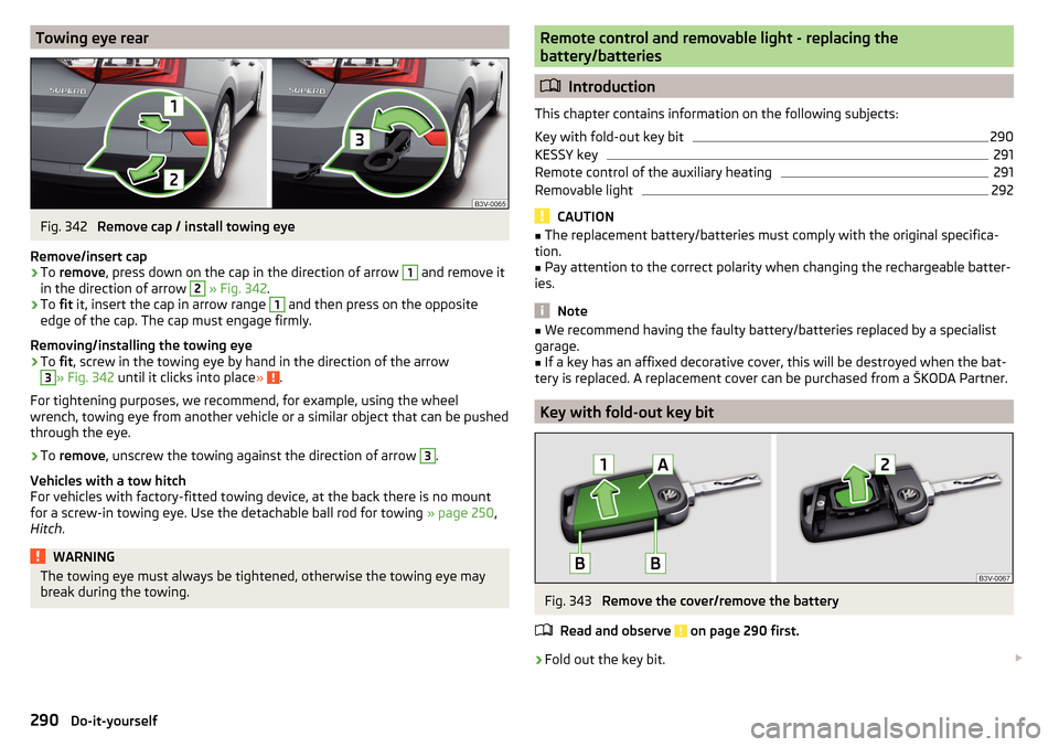
Towing eye rearFig. 342
Remove cap / install towing eye
Remove/insert cap
›
To remove , press down on the cap in the direction of arrow
1
and remove it
in the direction of arrow
2
» Fig. 342 .
›
To fit it, insert the cap in arrow range
1
and then press on the opposite
edge of the cap. The cap must engage firmly.
Removing/installing the towing eye
›
To fit, screw in the towing eye by hand in the direction of the arrow
3
» Fig. 342 until it clicks into place » .
For tightening purposes, we recommend, for example, using the wheel
wrench, towing eye from another vehicle or a similar object that can be pushed
through the eye.
›
To remove , unscrew the towing against the direction of arrow
3
.
Vehicles with a tow hitch
For vehicles with factory-fitted towing device, at the back there is no mount
for a screw-in towing eye. Use the detachable ball rod for towing » page 250,
Hitch .
WARNINGThe towing eye must always be tightened, otherwise the towing eye may
break during the towing.Remote control and removable light - replacing the
battery/batteries
Introduction
This chapter contains information on the following subjects:
Key with fold-out key bit
290
KESSY key
291
Remote control of the auxiliary heating
291
Removable light
292
CAUTION
■ The replacement battery/batteries must comply with the original specifica-
tion.■
Pay attention to the correct polarity when changing the rechargeable batter-
ies.
Note
■ We recommend having the faulty battery/batteries replaced by a specialist
garage.■
If a key has an affixed decorative cover, this will be destroyed when the bat-
tery is replaced. A replacement cover can be purchased from a ŠKODA Partner.
Key with fold-out key bit
Fig. 343
Remove the cover/remove the battery
Read and observe
on page 290 first.
›
Fold out the key bit.
290Do-it-yourself
Page 295 of 336
›On vehicles with the
KESSY system, hold the emergency key with the handle
facing downwards » Fig. 349 - into the lock cylinder and unlock / lock the
vehicle.›
Pull on the door handle and hold.
›
Replace the cover.
CAUTION
Make sure you do not damage the paint when performing an emergency lock-
ing/unlocking.
Locking the door without locking cylinders
Fig. 350
Emergency locking: Left/right rear door
›
Open the corresponding back door remove the trim
A
» Fig. 350 .
›
Insert the key into the slot and turn in the direction of the arrow (sprung po-
sition).
›
Replace the cover
A
.
After closing, the door is locked.
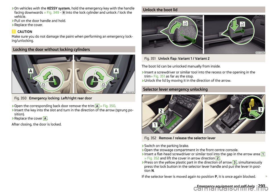
Unlock the boot lidFig. 351
Unlock flap: Variant 1 / Variant 2
The boot lid can be unlocked manually from inside.
›
Insert a screwdriver or similar tool into the recess or the opening in the
trim » Fig. 351 as far as the stop.
›
Unlock the lid by moving it in the direction of the arrow.
Selector lever emergency unlocking
Fig. 352
Remove / release the selector lever
›
Switch on the parking brake.
›
Open the stowage compartment in the front centre console.
›
Insert a flat-head screwdriver or similar tool into the gap in the arrow area
1
» Fig. 352 and lift the cover in arrow direction
2
.
›
Press on the yellow plastic part in the direction of arrow
3
, simultaneously
press the lock button in the selector lever handle and put the lever in posi-
tion N.
If the selector lever is moved again to position P, it is once again blocked.
293Emergency equipment and self-help