warning lights SKODA SUPERB 2016 3.G / (B8/3V) Service Manual
[x] Cancel search | Manufacturer: SKODA, Model Year: 2016, Model line: SUPERB, Model: SKODA SUPERB 2016 3.G / (B8/3V)Pages: 336, PDF Size: 53.89 MB
Page 236 of 336
OperationFig. 294
Instrument cluster display: Examples of ACC displays
Fig. 295
Instrument cluster display: Examples of ACC status displays
Read and observe
on page 233 first.
The ACC allows you to set a speed of 30 - 160 or 210 km / h (depending on
equipment) and the distance to the vehicle ahead in the range of a very short
to a very long distance.
The ACC adjusts the set speed with respect to the detected vehicle ahead,
thus maintaining the selected proximity.
The ACC can detect a vehicle that is up to approx. 150 m ahead using the radar
sensor.
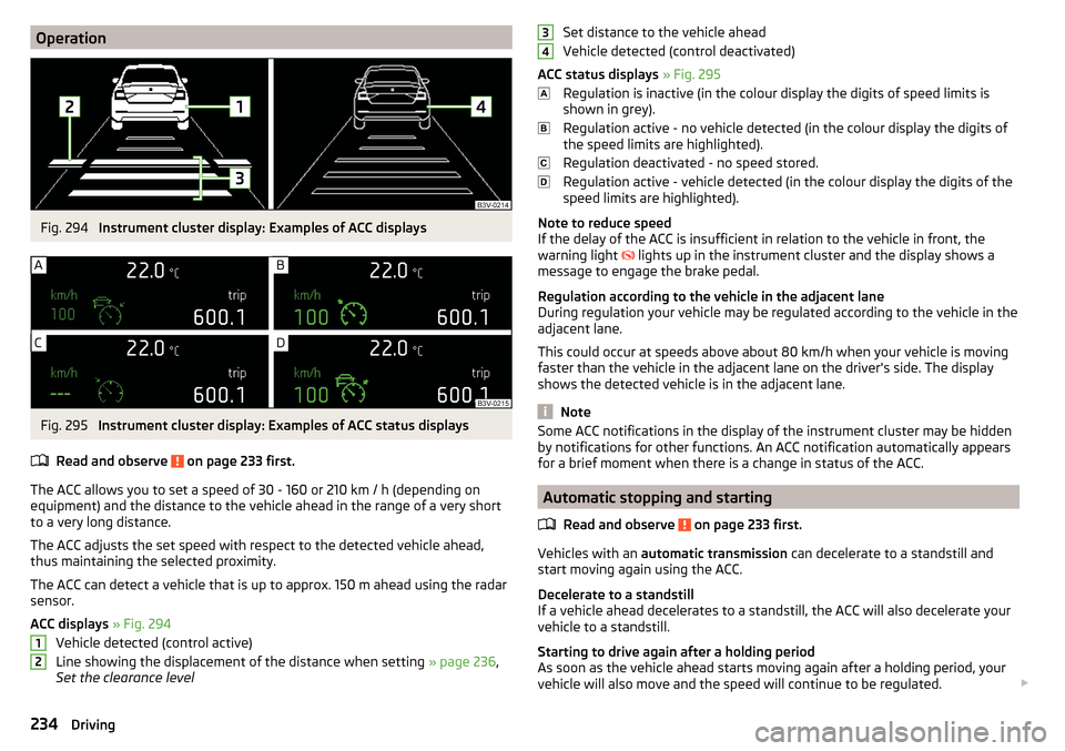
ACC displays » Fig. 294
Vehicle detected (control active)
Line showing the displacement of the distance when setting » page 236,
Set the clearance level
12Set distance to the vehicle ahead
Vehicle detected (control deactivated)
ACC status displays » Fig. 295
Regulation is inactive (in the colour display the digits of speed limits is
shown in grey).
Regulation active - no vehicle detected (in the colour display the digits of
the speed limits are highlighted).
Regulation deactivated - no speed stored.
Regulation active - vehicle detected (in the colour display the digits of the
speed limits are highlighted).
Note to reduce speed
If the delay of the ACC is insufficient in relation to the vehicle in front, the
warning light lights up in the instrument cluster and the display shows a
message to engage the brake pedal.
Regulation according to the vehicle in the adjacent lane
During regulation your vehicle may be regulated according to the vehicle in the
adjacent lane.
This could occur at speeds above about 80 km/h when your vehicle is moving
faster than the vehicle in the adjacent lane on the driver's side. The display
shows the detected vehicle is in the adjacent lane.
Note
Some ACC notifications in the display of the instrument cluster may be hidden
by notifications for other functions. An ACC notification automatically appears
for a brief moment when there is a change in status of the ACC.
Automatic stopping and starting
Read and observe
on page 233 first.
Vehicles with an automatic transmission can decelerate to a standstill and
start moving again using the ACC.
Decelerate to a standstill
If a vehicle ahead decelerates to a standstill, the ACC will also decelerate your
vehicle to a standstill.
Starting to drive again after a holding period
As soon as the vehicle ahead starts moving again after a holding period, your
vehicle will also move and the speed will continue to be regulated.
34234Driving
Page 244 of 336
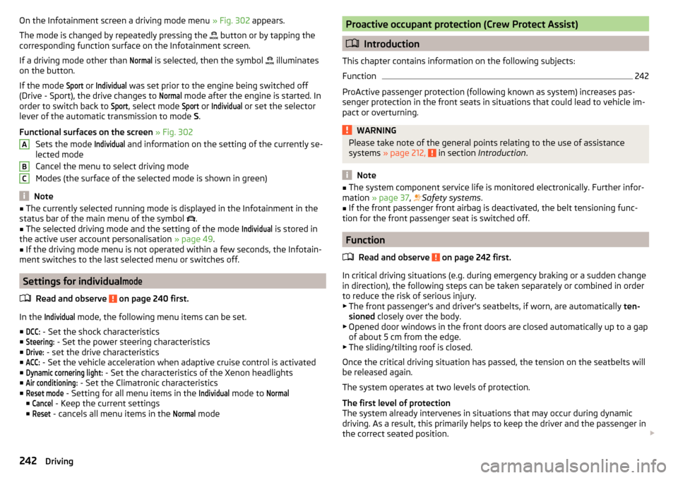
On the Infotainment screen a driving mode menu » Fig. 302 appears.
The mode is changed by repeatedly pressing the
button or by tapping the
corresponding function surface on the Infotainment screen.
If a driving mode other than Normal
is selected, then the symbol
illuminates
on the button.
If the mode
Sport
or
Individual
was set prior to the engine being switched off
(Drive - Sport), the drive changes to
Normal
mode after the engine is started. In
order to switch back to
Sport
, select mode
Sport
or
Individual
or set the selector
lever of the automatic transmission to mode S.
Functional surfaces on the screen » Fig. 302
Sets the mode
Individual
and information on the setting of the currently se-
lected mode
Cancel the menu to select driving mode
Modes (the surface of the selected mode is shown in green)
Note
■ The currently selected running mode is displayed in the Infotainment in the
status bar of the main menu of the symbol .■
The selected driving mode and the setting of the mode
Individual
is stored in
the active user account personalisation » page 49.
■
If the driving mode menu is not operated within a few seconds, the Infotain-
ment switches to the last selected menu or switches off.
Settings for individual
mode
Read and observe on page 240 first.
In the
Individual
mode, the following menu items can be set.
■
DCC:
- Set the shock characteristics
■
Steering:
- Set the power steering characteristics
■
Drive:
- set the drive characteristics
■
ACC:
- Set the vehicle acceleration when adaptive cruise control is activated
■
Dynamic cornering light:
- Set the characteristics of the Xenon headlights
■
Air conditioning:
- Set the Climatronic characteristics
■
Reset mode
- Setting for all menu items in the
Individual
mode to
Normal
■
Cancel
- Keep the current settings
■
Reset
- cancels all menu items in the
Normal
mode
ABCProactive occupant protection (Crew Protect Assist)
Introduction
This chapter contains information on the following subjects:
Function
242
ProActive passenger protection (following known as system) increases pas-
senger protection in the front seats in situations that could lead to vehicle im-
pact or overturning.
WARNINGPlease take note of the general points relating to the use of assistance
systems » page 212, in section Introduction .
Note
■
The system component service life is monitored electronically. Further infor-
mation » page 37 , Safety systems .■
If the front passenger front airbag is deactivated, the belt tensioning func-
tion for the front passenger seat is switched off.
Function
Read and observe
on page 242 first.
In critical driving situations (e.g. during emergency braking or a sudden changein direction), the following steps can be taken separately or combined in order
to reduce the risk of serious injury.
▶ The front passenger's and driver's seatbelts, if worn, are automatically ten-
sioned closely over the body.
▶ Opened door windows in the front doors are closed automatically up to a gap
of about 5 cm from the edge.
▶ The sliding/tilting roof is closed.
Once the critical driving situation has passed, the tension on the seatbelts will
be released again.
The system operates at two levels of protection.
The first level of protection
The system already intervenes in situations that may occur during dynamic
driving. As a result, this primarily helps to keep the driver and the passenger in
the correct seated position.
242Driving
Page 246 of 336
OperationFig. 304
Monochromatic display of the instrument cluster: Examples of
system indications
Fig. 305
Colour display of the instrument cluster: Examples of system in-
dications
Read and observe
and on page 243 first.
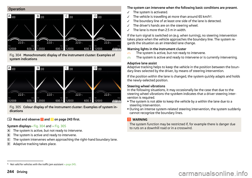
System displays » Fig. 304 and » Fig. 305
The system is active, but not ready to intervene.
The system is active and ready to intervene.
The system intervenes when approaching the right-hand boundary lane.
Adaptive tracking takes place.
The system can intervene when the following basic conditions are present. The system is activated.
The vehicle is travelling at more than around 65 km/h 1)
.
The boundary line of at least one side of the lane is detected.
The driver's hands are on the steering wheel.
The lane is more than 2.5 m in width.
If the turn signal is switched on (e.g. when turning), no steering intervention takes place when the vehicle approaches the boundary line. The system re-
gards the situation as an intended lane change.
Warning lights in the instrument cluster The system is active, but not ready to intervene.
The system is active and ready to intervene or is currently intervening.
Adaptive lane assist
Adaptive tracking helps to keep the vehicle in the position between the boun-
dary lines selected by the driver, by means of steering intervention.
If the position within the lane is changed, the system quickly adapts and holds
the newly-selected position.
Steering wheel vibrations
In the following situations, it may occasionally be the case that due to the
steering wheel vibrations the syst4em indicates that a driver steering inter-
vention is required.
▶ The system is not able to keep the vehicle by a within the lane due to a
steering intervention.
▶ During an intense system-related steering intervention, the system suddenly
cannot recognize the boundary lines.WARNINGThe system function may be restricted if, for example there is danger due
to ruts on a downhill road or in a crosswind.1)
Not valid for vehicles with the traffic jam assistant » page 245.
244Driving
Page 251 of 336
WARNING■Please take note of the general points relating to the use of assistance
systems » page 212, in section Introduction .■
For the driving ability is always the driver's responsibility. Never drive if
you feel tired.
■
The system may not detect all cases where a break is needed.
■
Therefore, take regular, sufficient breaks during long trips.
■
There will be no system warning during the so-called micro-sleep.
Note
■ In some situations, the system may evaluate the driving incorrectly and thus
mistakenly recommend a break (e.g. sporty driving, adverse weather condi-
tions or poor road conditions).■
The system is designed primarily for use on motorways.
Tyre pressure monitoring
Introduction
This chapter contains information on the following subjects:
Storing the tyre pressure values and Infotainment display
249
The tyre pressure monitoring function (following known as system) monitors
the tyre pressure while driving.
If the tyre inflation pressure changes, the warning light
lights up in the in-
strument cluster and an audible signal sounds » page 37.
The system can only function properly if the tyres have the prescribed inflation
pressure and these pressure values are stored in the system.
Always save the tyre pressure values in the system if one of the following
events occurs.
▶ Change of tyre pressure values.
▶ Change one or more wheels.
▶ Change in position of a wheel on the vehicle.
▶ The warning light
in the instrument cluster.
WARNING■
Please take note of the general points relating to the use of assistance
systems » page 212, in section Introduction .■
Having the correct tyre inflation pressure is always the driver's responsi-
bility. Tyre pressure should be checked regularly » page 277.
■
The system cannot warn in case of very rapid tyre inflation pressure loss,
e.g. in case of sudden tyre damage.
■
Before storing the pressures, the tyres must be inflated to the specified
inflation pressure » page 277. If the wrong pressure valuesare stored, the
system may not issue any warnings, even if the tyre pressure is too low.
CAUTION
To ensure proper system function, the tire pressure values must be stored ev-
ery 10 000 km or 1x a year.
Storing the tyre pressure values and Infotainment display
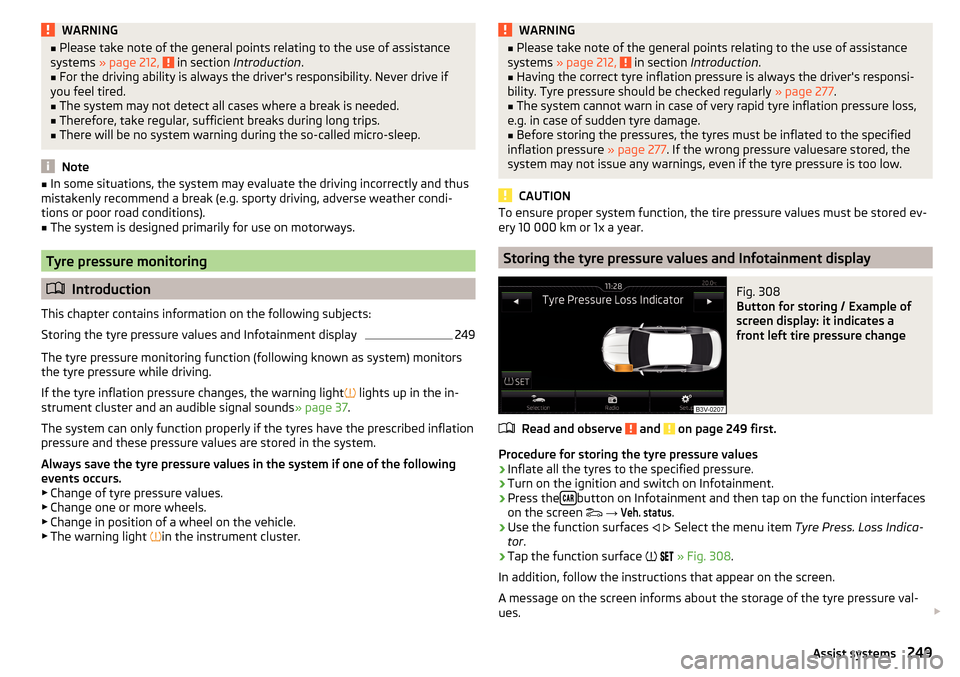
Fig. 308
Button for storing / Example of
screen display: it indicates a
front left tire pressure change
Read and observe and on page 249 first.
Procedure for storing the tyre pressure values
›
Inflate all the tyres to the specified pressure.
›
Turn on the ignition and switch on Infotainment.
›
Press the button on Infotainment and then tap on the function interfaces
on the screen
→
Veh. status
.
›
Use the function surfaces
Select the menu item
Tyre Press. Loss Indica-
tor .
›
Tap the function surface
» Fig. 308 .
In addition, follow the instructions that appear on the screen.
A message on the screen informs about the storage of the tyre pressure val- ues.
249Assist systems
Page 253 of 336
›Press the tow bar in the direction of the arrow 2, until it audibly clicks into
place. The warning light lights green.
Swivel tow bar
No trailer or other accessory is connected to the tow bar. A socket or adapter
may not be plugged into the 13-pin socket.›
Pull the release lever
A
in the direction of arrow
1
» Fig. 309 . The tow bar
is unlocked and the warning light beside the handle flashes red.
›
Allow the handle
A
to retract slowly and check if this is properly seated in
the starting position.
›
Swing in the tow bar under the bumper in the direction of arrow
3
until it
clicks into place. The warning light lights green.
Check latching
If the tow bar is incorrectly locked, the warning light flashes red, after the igni-
tion is switched on an acoustic signal is sounded and the following message
appears in the instrument cluster.
WARNING■ Take care with the towing device - it may cause injury.■When swinging out the ball rod away from the central area of the rear
bumper, there is a danger of injury to the legs.■
Do not manipulate the release lever as long as a trailer or another acces-
sory is coupled to the tow bar. The tow bar could come loose - risk of acci-
dent and injury.
■
If the warning light does not turn green, or the tow bar cannot engage,
then do not use the tow bar. Seek help from a specialist garage.
Note
When not using the towing device, always swing the tow bar under the bump-
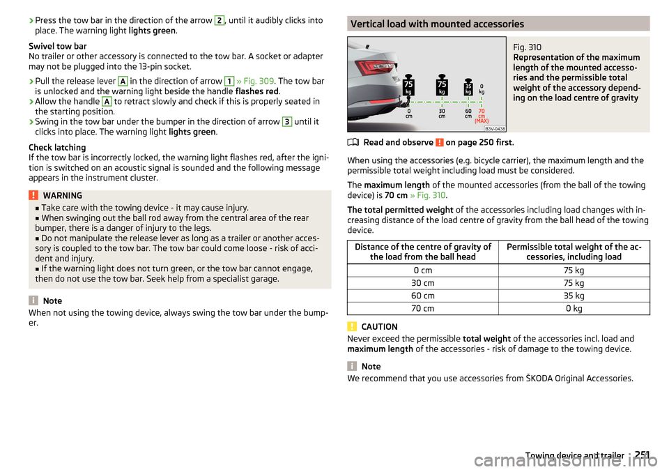
er.Vertical load with mounted accessoriesFig. 310
Representation of the maximum
length of the mounted accesso-
ries and the permissible total
weight of the accessory depend-
ing on the load centre of gravity
Read and observe on page 250 first.
When using the accessories (e.g. bicycle carrier), the maximum length and the
permissible total weight including load must be considered.
The maximum length of the mounted accessories (from the ball of the towing
device) is 70 cm » Fig. 310 .
The total permitted weight of the accessories including load changes with in-
creasing distance of the load centre of gravity from the ball head of the towing
device.
Distance of the centre of gravity of the load from the ball headPermissible total weight of the ac- cessories, including load0 cm75 kg30 cm75 kg60 cm35 kg70 cm0 kg
CAUTION
Never exceed the permissible total weight of the accessories incl. load and
maximum length of the accessories - risk of damage to the towing device.
Note
We recommend that you use accessories from ŠKODA Original Accessories.251Towing device and trailer
Page 254 of 336
Using hitch
Trailer (accessory) connect and disconnect
Fig. 311
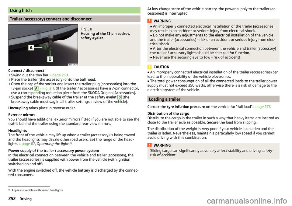
Housing of the 13 pin socket,
safety eyelet
Connect / disconnect
›
Swing out the tow bar » page 250.
›
Place the trailer (the accessory) onto the ball head.
›
Open the cap of the socket and insert the trailer plug (accessories) into the
13-pin socket
A
» Fig. 311 . (If the trailer / accessories have a 7-pin connector,
use a corresponding reduction piece from the ŠKODA Original Accessories).
›
Suspend the breakaway cable of the trailer at the safety eyelet
B
(the
breakaway cable must sag in all trailer settings in view of the vehicle).
Uncoupling takes place in reverse order.
Exterior mirrors
You should have additional exterior mirrors fitted if you are not able to see the
traffic behind the trailer using the standard rear-view mirrors.
Headlights
The front of the vehicle may lift up when a trailer (accessory) is being towed
and the headlights may dazzle other road users. Set the range of the head-
lights » page 67 , Operating the lights 1)
.
Power supply of the trailer / accessory power system
In the electrical connection between the vehicle and trailer (accessory), the
trailer (accessories) is supplied with power from the vehicle (with ignition
switched on and off).
With the engine switched off, the vehicle battery is discharged by the connec-
ted consumers.
At low charge state of the vehicle battery, the power supply to the trailer (ac-
cessories) is interrupted.WARNING■ An improperly connected electrical installation of the trailer (accessories)
may result in an accident or serious injury from electrical shock.■
Do not make any adjustments to the electrical installation of the vehicle
and the trailer (accessories) - risk of an accident or serious injury from elec-
trical shock.
■
After the electrical connection between the vehicle and trailer (accessory)
the trailer / accessory lights should be checked for function.
■
Never use the securing eye to tow - risk of accident!
CAUTION
■ An improperly connected electrical installation of the trailer (accessories) can
lead to the inoperability of the vehicle electronics.■
The total power consumption of all the connected loads to the trailer power
supply must not exceed 350 watts, otherwise there is a risk of damage to the
electrical system of the vehicle.
Loading a trailer
Correct the tyre inflation pressure on the vehicle for “full load” » page 277.
Distribution of the cargo
Distribute the cargo in the trailer in such a way that heavy items are located as
close to the trailer axle as possible. Secure the load from slipping.
The distribution of the weight is very poor if your vehicle is unladen and the
trailer is laden. Nevertheless, maintain a particularly low speed if you cannot
avoid driving with this combination.
WARNINGSliding cargo can significantly adversely affect stability and driving safety -
risk of accident!1)
Applies to vehicles with xenon headlights.
252Driving
Page 257 of 336
WARNINGAlways drive particularly carefully with the trailer.
CAUTION
With frequent towing, the vehicle is excessively loaded so this must also be
checked between service intervals.
Anti-theft alarm system
The alarm is triggered if, with a vehicle with activated anti-theft alarm (herein-
after only warning system), the electrical connection to the trailer (accessory)
is interrupted.
Always switch off the anti-theft alarm system before a trailer (accessory) is
coupled or uncoupled » page 58.
Conditions for including a trailer (accessory) in the anti-theft alarm system. The vehicle is factory-fitted with an anti-theft alarm system and a towing
device.
The trailer (accessory) is electrically connected to the towing vehicle by
means of the trailer socket.
The electrical system of the vehicle and trailer (accessory) is functional.
The vehicle is locked and the anti-theft alarm system is activated.
The trailer (accessory) is not equipped with LED taillights.
255Towing device and trailer
Page 272 of 336
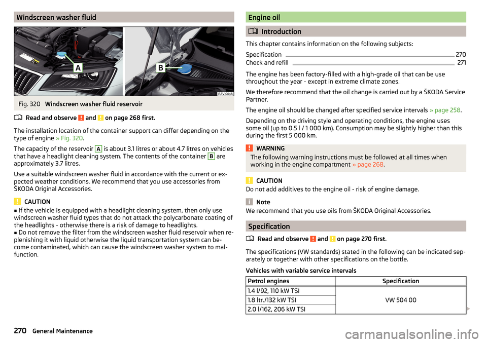
Windscreen washer fluidFig. 320
Windscreen washer fluid reservoir
Read and observe
and on page 268 first.
The installation location of the container support can differ depending on the
type of engine » Fig. 320.
The capacity of the reservoir
A
is about 3.1 litres or about 4.7 litres on vehicles
that have a headlight cleaning system. The contents of the container
B
are
approximately 3.7 litres.
Use a suitable windscreen washer fluid in accordance with the current or ex-
pected weather conditions. We recommend that you use accessories from
ŠKODA Original Accessories.
CAUTION
■ If the vehicle is equipped with a headlight cleaning system, then only use
windscreen washer fluid types that do not attack the polycarbonate coating of
the headlights - otherwise there is a risk of damage to headlights.■
Do not remove the filter from the windscreen washer fluid reservoir when re-
plenishing it with liquid otherwise the liquid transportation system can be-
come contaminated, which can cause the windscreen washer system to mal-
function.
Engine oil
Introduction
This chapter contains information on the following subjects:
Specification
270
Check and refill
271
The engine has been factory-filled with a high-grade oil that can be use
throughout the year - except in extreme climate zones.
We therefore recommend that the oil change is carried out by a ŠKODA Service
Partner.
The engine oil should be changed after specified service intervals » page 258.
Depending on the driving style and operating conditions, the engine uses
some oil (up to 0.5 l / 1 000 km). Consumption may be slightly higher than this
during the first 5 000 km.
WARNINGThe following warning instructions must be followed at all times when
working in the engine compartment » page 268.
CAUTION
Do not add additives to the engine oil - risk of engine damage.
Note
We recommend that you use oils from ŠKODA Original Accessories.
Specification
Read and observe
and on page 270 first.
The specifications (VW standards) stated in the following can be indicated sep-arately or together with other specifications on the bottle.
Vehicles with variable service intervals
Petrol enginesSpecification1.4 l/92, 110 kW TSI
VW 504 00
1.8 ltr./132 kW TSI2.0 l/162, 206 kW TSI 270General Maintenance
Page 274 of 336
The coolant additive proportion in the coolant must be between 40 and 60 %.
The correct mixing ratio of water and coolant additive should be checked if
necessary by a specialist garage or corrected if necessary.WARNING■ The following warning instructions must be followed at all times when
working in the engine compartment » page 268.■
Never open the end cover of the coolant expansion reservoir while the
engine is still warm. The cooling system is pressurized - risk of scalding or
injury from being splashed with coolant!
■
To protect against coolant splashes, cover the cap with a cloth when
opening.
■
Coolant and coolant fumes are harmful - avoid contact with the coolant. If
your eyes or skin come into contact with the coolant, immediately wash the
affected area for a few minutes long with a lot of water and seek medical
advice if required.
CAUTION
Do not cover the radiator or fit any parts (e.g. auxiliary lights) in front of the air
intakes - there is a risk of the engine overheating.
Checking and refilling
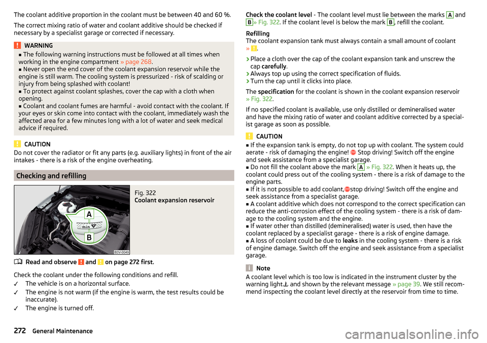
Fig. 322
Coolant expansion reservoir
Read and observe and on page 272 first.
Check the coolant under the following conditions and refill.
The vehicle is on a horizontal surface.
The engine is not warm (if the engine is warm, the test results could be
inaccurate).
The engine is turned off.
Check the coolant level - The coolant level must lie between the marks A andB» Fig. 322. If the coolant level is below the mark B, refill the coolant.
Refilling
The coolant expansion tank must always contain a small amount of coolant
»
.
›
Place a cloth over the cap of the coolant expansion tank and unscrew the
cap carefully .
›
Always top up using the correct specification of fluids.
›
Turn the cap until it clicks into place.
The specification for the coolant is shown in the coolant expansion reservoir
» Fig. 322 .
If no specified coolant is available, use only distilled or demineralised water
and have the mixing ratio of water and coolant additive corrected by a special-
ist garage as soon as possible.
CAUTION
■ If the expansion tank is empty, do not top up with coolant. The system could
aerate - risk of damaging the engine! Stop driving! Switch off the engine
and seek assistance from a specialist garage.■
Do not fill the coolant above the mark
A
» Fig. 322 . When it heats up, the
coolant could press out of the cooling system - there is a risk of damage to the
engine parts.
■
If it is not possible to add coolant,
stop driving! Switch off the engine and
seek assistance from a specialist garage.
■
A coolant additive which does not correspond to the correct specification can
reduce the anti-corrosion effect of the cooling system - there is a risk of dam-
age to the cooling system and the engine.
■
If water other than distilled (demineralised) water is used, then have the
coolant replaced by a specialist garage - there is a risk of engine damage.
■
A loss of coolant could be due to leaks in the cooling system - there is a risk
of engine damage. Switch off the engine and seek assistance from a specialist
garage.
Note
A coolant level which is too low is indicated in the instrument cluster by the
warning light and shown by the relevant message » page 39. We still recom-
mend inspecting the coolant level directly at the reservoir from time to time.272General Maintenance
Page 291 of 336
The maximum towing speed is 50 km/h.
The vehicle must be transported on a special breakdown vehicle or trailer
if it is not possible to tow in the vehicle in the way described or if the tow-
ing distance is greater than 50 km.
Driver of the tow vehicle›
On vehicles with manual transmission , engage gear slowly when starting.
›
On vehicles with automatic transmission , accelerate with particular care.
›
Only then approach correctly when the rope is taut.
Driver of the towed vehicle
›
If possible, the vehicle should be towed with the engine running. Operate the
brake booster and power steering only if the engine is running, otherwise
the brake pedal must be depressed more strongly and more power has to be
directed to the steering.
›
If it is not possible to start the engine, switch on the ignition so that the
steering wheel is not locked and so that the turn signal lights, windscreen
wipers and windscreen washer system can be used.
›
Take the vehicle out of gear or move the selector lever into position N if the
vehicle is fitted with an automatic gearbox.
›
Always keep the tow rope taut during the towing procedure.
WARNING■ Wound tow ropes must not be used for towing » Fig. 340- , the towing
eye may unscrew out of the vehicle - risk of accident.■
Ensure tow rope is not twisted - risk of accident.
CAUTION
■ Do not tow-start the engine – risk of damaging the engine! The battery from
another vehicle can be used as a jump-start aid » page 287, Jump-starting .■
In the case of off-road towing manoeuvres, for both vehicles there is the risk
that the fastening parts could be overloaded and damaged.
Note
We recommend that you use the tow rope from ŠKODA Original Accessories.Front towing eyeFig. 341
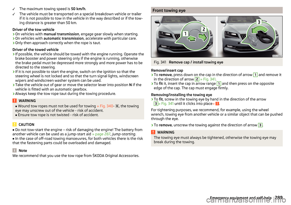
Remove cap / install towing eye
Remove/insert cap
›
To remove , press down on the cap in the direction of arrow
1
and remove it
in the direction of arrow
2
» Fig. 341 .
›
To fit it, insert the cap in arrow range
1
and then press on the opposite
edge of the cap. The cap must engage firmly.
Removing/installing the towing eye
›
To fit, screw in the towing eye by hand in the direction of the arrow
3
» Fig. 341 until it clicks into place » .
For tightening purposes, we recommend, for example, using the wheel
wrench, towing eye from another vehicle or a similar object that can be pushed
through the eye.
›
To remove , unscrew the towing against the direction of arrow
3
.
WARNINGThe towing eye must always be tightened, otherwise the towing eye may
break during the towing.289Emergency equipment and self-help