bulb SKODA SUPERB 2016 3.G / (B8/3V) Owner's Manual
[x] Cancel search | Manufacturer: SKODA, Model Year: 2016, Model line: SUPERB, Model: SKODA SUPERB 2016 3.G / (B8/3V)Pages: 336, PDF Size: 53.89 MB
Page 6 of 336
Emergency unlocking / unlocking of doors292Replacing windscreen wiper blades294
Fuses and light bulbs
295
Fuses
295
Bulbs
299
Technical data
Technical data
303
Basic vehicle data
303
Vehicle-specific details per engine type
309
Index
4Table of Contents
Page 40 of 336
Other incidents
The illumination of the warning light can have the following reasons.
▶ The vehicle is loaded on one side. Distribute the load evenly.
▶ The wheels of one axle are loaded more heavily (e.g. when towing a trailer or
when driving uphill or downhill).
▶ Snow chains are mounted.
▶ A wheel has been changed.
CAUTION
Under certain circumstances (e.g. sporty style of driving, wintry or unpaved
roads) the warning light can be delayed or does not light up at all.
Brake linings
Read and observe
on page 34 first.
illuminates - the brake pads are worn.
▶ You can drive on, exercising appropriate caution. Seek assistance from a spe-
cialist garage immediately.
Fuel reserve
Read and observe
on page 34 first.
illuminates – the fuel level in the fuel tank is at the reserve level (approxi-
mately 6 litres).
An audible signal sounds as a warning. ▶ Please refuel » page 265.
Note
The text in the display goes out after refuelling and driving a short distance.
Lane Departure Warning (Lane Assist)
Read and observe
on page 34 first.
The warning lights
indicates the state of the Lane Assist system.
More information about the Lane Assist System » page 243.
Turn signal system
Read and observe
on page 34 first.
flashes – the left turn signal is turned on.
flashes – the right turn signal is turned on.
If there is a fault in the turn signal system, the warning light flashes at twice
its normal rate (does not apply when towing).
When the hazard warning light system is switched on, this will cause all of the turn signal lights as well as both warning lights to flash.
Trailer turn signal lights
Read and observe
on page 34 first.
flashes – the trailer turn signal lights are switched on.
If a trailer is hitched and the warning light is not flashing, one of the trailer
turn signal lights has failed.
▶ Check the trailer bulbs.
Fog lights
Read and observe
on page 34 first.
illuminates – the fog lights are switched on.
Speed regulating system / speed limiter
Read and observe
on page 34 first.
illuminates - the vehicle speed is limited by the speed regulating system
and/or the adaptive cruise control or by the speed limiter.
flashes – the speed set with the speed limiter has been exceeded.
Brake pedal (automatic gearbox)
Read and observe
on page 34 first.
lights up – apply the brake.
38Using the system
Page 100 of 336

WARNING■Make sure that no liquid or moisture enters into the socket - it can be fa-
tal! If fluid does manage to get into the power socket, completely dry out
the socket before reuse.■
The child lock on the power socket is unlocked when using adapters and
extension cables which carry volts – risk of injury!
■
Do no insert any objects (e.g. knitting needles) into the contacts of the
power socket – risk of death!
CAUTION
■ The power socket can only be used for connecting approved electrical acces-
sories with a two-pin 230V plug, with a total power uptake of up to 150 watt.■
The plug of the electrical appliance must be plugged in up to the stop, other-
wise the child safety lock can be unlocked and the socket may be activated but
the electric appliance is still not receiving power.
■
Do not connect bulbs with neon tubes in the socket - there is a risk of dam-
aging the lamp.
■
For appliances with an independent power source (e.g. such as notebooks),
first connect the power source itself and only after that connect the appliance.
Ashtray and cigarette lighter
Introduction
This chapter contains information on the following subjects:
Ashtray
98
Cigarette lighter
99
The ashtray can be used for ash, cigarettes, cigars and the like.
WARNINGNever place hot or flammable objects in the ashtray – risk of fire!AshtrayFig. 113
Remove front ashtray / remove front ashtray insert / remove rear
ashtray insert
Read and observe
on page 98 first.
Removable ashtray
›
Hold the ashtray
A
(not by the lid) remove in the direction of the arrow
» Fig. 113 .
To insert , proceed in reverse order.
Ashtray with removable insert
›
To remove , open the insert of the ashtray, hold the insert in the area
B
and
remove in the direction of the arrow » Fig. 113.
To insert , proceed in reverse order.
98Using the system
Page 297 of 336
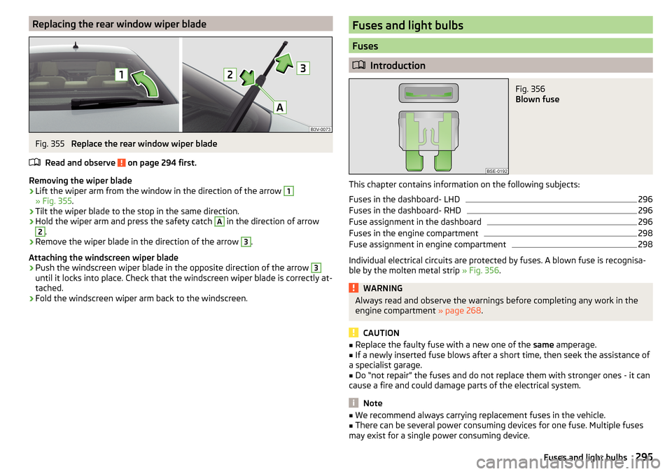
Replacing the rear window wiper bladeFig. 355
Replace the rear window wiper blade
Read and observe
on page 294 first.
Removing the wiper blade
›
Lift the wiper arm from the window in the direction of the arrow
1
» Fig. 355 .
›
Tilt the wiper blade to the stop in the same direction.
›
Hold the wiper arm and press the safety catch
A
in the direction of arrow
2
.
›
Remove the wiper blade in the direction of the arrow
3
.
Attaching the windscreen wiper blade
›
Push the windscreen wiper blade in the opposite direction of the arrow
3
until it locks into place. Check that the windscreen wiper blade is correctly at-
tached.
›
Fold the windscreen wiper arm back to the windscreen.
Fuses and light bulbs
Fuses
Introduction
Fig. 356
Blown fuse
This chapter contains information on the following subjects:
Fuses in the dashboard- LHD
296
Fuses in the dashboard- RHD
296
Fuse assignment in the dashboard
296
Fuses in the engine compartment
298
Fuse assignment in engine compartment
298
Individual electrical circuits are protected by fuses. A blown fuse is recognisa-
ble by the molten metal strip » Fig. 356.
WARNINGAlways read and observe the warnings before completing any work in the
engine compartment » page 268.
CAUTION
■
Replace the faulty fuse with a new one of the same amperage.■If a newly inserted fuse blows after a short time, then seek the assistance of
a specialist garage.■
Do “not repair” the fuses and do not replace them with stronger ones - it can
cause a fire and could damage parts of the electrical system.
Note
■ We recommend always carrying replacement fuses in the vehicle.■There can be several power consuming devices for one fuse. Multiple fuses
may exist for a single power consuming device.295Fuses and light bulbs
Page 299 of 336
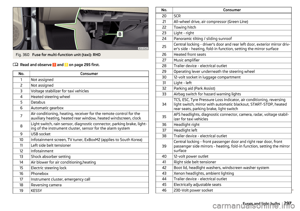
Fig. 360
Fuse for multi-function unit (taxi): RHD
Read and observe
and on page 295 first.
No.Consumer1Not assigned2Not assigned3Voltage stabilizer for taxi vehicles4Heated steering wheel5Databus6Automatic gearbox7Air conditioning, heating, receiver for the remote control for the
auxiliary heating, heated rear window, heated windscreen, clock8Light switch, rain sensor, diagnostic connector, parking brake, light-
ing of the instrument cluster, sensor for the alarm system9USB socket10Infotainment screen, TV tuner, ExBoxM2 (applies to South Korea)11Left side belt tensioner12Infotainment13Shock absorber setting14Air blower for air conditioning,heating15Electric steering lock16Phonebox17Instrument cluster, emergency call18Reversing camera19KESSYNo.Consumer20SCR21All-wheel drive, air compressor (Green Line)22Towing hitch23Light - right24Panoramic tilting / sliding sunroof25Central locking - driver's door and rear left door, exterior mirror driv-
er's side - heating, fold-in function, setting the mirror surface26Heated front seats27Music amplifier28Trailer device - electrical outlet29Operating lever underneath the steering wheel3012-volt socket in luggage compartment31Light - left32Parking aid (Park Assist)33Airbag switch for hazard warning lights34TCS, ESC, Tyre Pressure Loss Indicator, air conditioning, reversing
light switch, mirror with automatic blackout, START-STOP, heated
rear seats, parking brake, light switch35AFS headlights, diagnostic connector, camera, radar, voltage stabil-
izer for taxi vehicles36Headlight right37Headlight left38Trailer device - electrical outlet39Central locking - front passenger door and right rear door, front
passenger side mirrors - heating, fold-in function, setting the mirror
surface4012-volt power outlet41Right side belt tensioner42Boot lid, headlight washers, windscreen washer system43Xenon headlights, ambient lighting44Trailer device - electrical outlet45Electrically adjustable seats46230-Volt power socket 297Fuses and light bulbs
Page 301 of 336
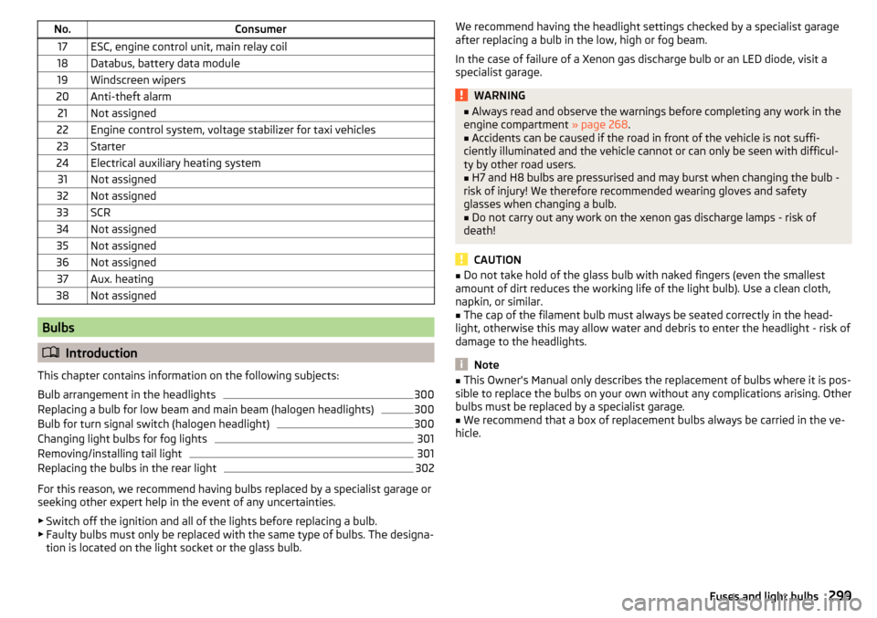
No.Consumer17ESC, engine control unit, main relay coil18Databus, battery data module19Windscreen wipers20Anti-theft alarm21Not assigned22Engine control system, voltage stabilizer for taxi vehicles23Starter24Electrical auxiliary heating system31Not assigned32Not assigned33SCR34Not assigned35Not assigned36Not assigned37Aux. heating38Not assigned
Bulbs
Introduction
This chapter contains information on the following subjects:
Bulb arrangement in the headlights
300
Replacing a bulb for low beam and main beam (halogen headlights)
300
Bulb for turn signal switch (halogen headlight)
300
Changing light bulbs for fog lights
301
Removing/installing tail light
301
Replacing the bulbs in the rear light
302
For this reason, we recommend having bulbs replaced by a specialist garage or
seeking other expert help in the event of any uncertainties.
▶ Switch off the ignition and all of the lights before replacing a bulb.
▶ Faulty bulbs must only be replaced with the same type of bulbs. The designa-
tion is located on the light socket or the glass bulb.
We recommend having the headlight settings checked by a specialist garage
after replacing a bulb in the low, high or fog beam.
In the case of failure of a Xenon gas discharge bulb or an LED diode, visit a
specialist garage.WARNING■ Always read and observe the warnings before completing any work in the
engine compartment » page 268.■
Accidents can be caused if the road in front of the vehicle is not suffi-
ciently illuminated and the vehicle cannot or can only be seen with difficul-
ty by other road users.
■
H7 and H8 bulbs are pressurised and may burst when changing the bulb -
risk of injury! We therefore recommended wearing gloves and safety
glasses when changing a bulb.
■
Do not carry out any work on the xenon gas discharge lamps - risk of
death!
CAUTION
■ Do not take hold of the glass bulb with naked fingers (even the smallest
amount of dirt reduces the working life of the light bulb). Use a clean cloth,
napkin, or similar.■
The cap of the filament bulb must always be seated correctly in the head-
light, otherwise this may allow water and debris to enter the headlight - risk of
damage to the headlights.
Note
■ This Owner's Manual only describes the replacement of bulbs where it is pos-
sible to replace the bulbs on your own without any complications arising. Other
bulbs must be replaced by a specialist garage.■
We recommend that a box of replacement bulbs always be carried in the ve-
hicle.
299Fuses and light bulbs
Page 302 of 336

Bulb arrangement in the headlightsFig. 363
Left headlight
Read and observe and on page 299 first.
The vehicle is equipped with headlights with halogen lamps or with a xenon
discharge lamp and an LED lighting element.
Bulb arrangement » Fig. 363
Flashing
Low beam with halogen bulb or Xenon gas discharge bulb
Main beam
Replacing a bulb for low beam and main beam (halogen headlights)
Fig. 364
Removing bulbs for low and main beam
Read and observe
and on page 299 first.
›
Remove the protective caps
B
and
C
» Fig. 363 on page 300 .
›
Turn the holder with the bulb in the direction of arrow
1
» Fig. 364 .
›
Remove the holder with the bulb in the direction of arrow
2
.
ABC›Remove the bulb from the holder in the direction of the arrow 3.›Insert a new bulb into the connector so that the lug A on the connector
snaps into the groove on the bulb.›
Insert the connector with the new bulb into the headlight in the opposite di-
rection to the arrow
2
.
›
Turn the connector with the new bulb in the opposite direction to the arrow
1
until it stops.
›
Use the protective caps
B
and
C
» Fig. 363 on page 300 .
Bulb for turn signal switch (halogen headlight)
Fig. 365
Changing the bulb for the turn signal light
Read and observe
and on page 299 first.
›
Remove the protective cap
A
» Fig. 363 on page 300 .
›
Remove the bulb holder with the bulb by jiggling it out in the direction of the
arrow
1
» Fig. 365 .
›
Hold the socket with the bulb at the position shown by the arrows.
›
Remove the faulty bulb from the holder in the direction of the arrow
2
.
›
Push a new bulb into the bulb holder up to the stop.
›
Slide the socket with the bulb with the fixing lug
B
upwards so that it fits
into the recess on the reflector.
›
Fit the protective cap
A
» Fig. 363 on page 300 .
300Do-it-yourself
Page 303 of 336
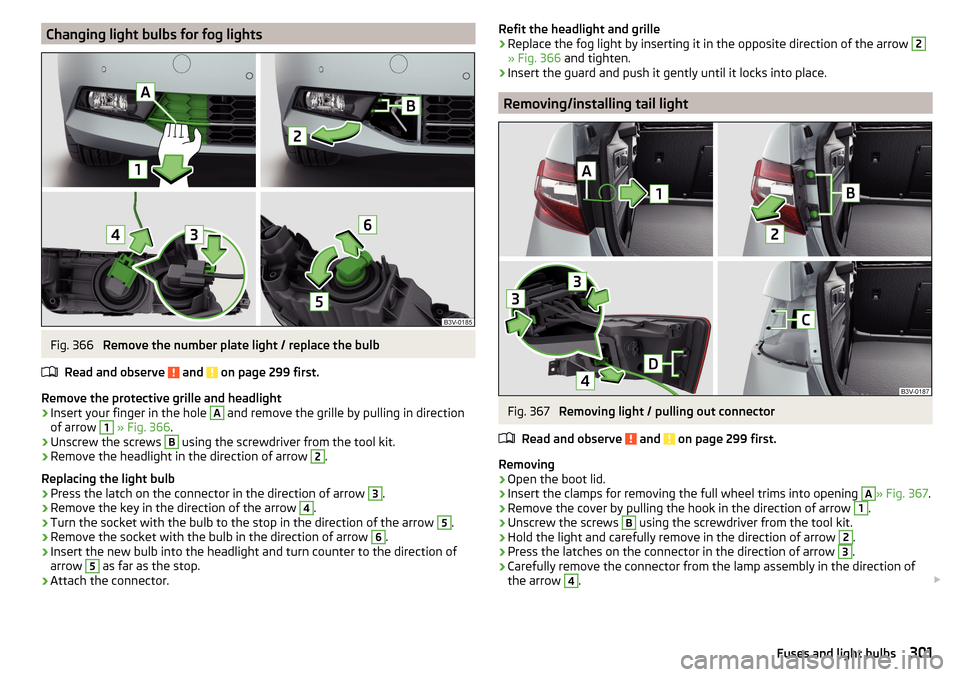
Changing light bulbs for fog lightsFig. 366
Remove the number plate light / replace the bulb
Read and observe
and on page 299 first.
Remove the protective grille and headlight
›
Insert your finger in the hole
A
and remove the grille by pulling in direction
of arrow
1
» Fig. 366 .
›
Unscrew the screws
B
using the screwdriver from the tool kit.
›
Remove the headlight in the direction of arrow
2
.
Replacing the light bulb
›
Press the latch on the connector in the direction of arrow
3
.
›
Remove the key in the direction of the arrow
4
.
›
Turn the socket with the bulb to the stop in the direction of the arrow
5
.
›
Remove the socket with the bulb in the direction of arrow
6
.
›
Insert the new bulb into the headlight and turn counter to the direction of
arrow
5
as far as the stop.
›
Attach the connector.
Refit the headlight and grille›Replace the fog light by inserting it in the opposite direction of the arrow 2
» Fig. 366 and tighten.
›
Insert the guard and push it gently until it locks into place.
Removing/installing tail light
Fig. 367
Removing light / pulling out connector
Read and observe
and on page 299 first.
Removing
›
Open the boot lid.
›
Insert the clamps for removing the full wheel trims into opening
A
» Fig. 367 .
›
Remove the cover by pulling the hook in the direction of arrow
1
.
›
Unscrew the screws
B
using the screwdriver from the tool kit.
›
Hold the light and carefully remove in the direction of arrow
2
.
›
Press the latches on the connector in the direction of arrow
3
.
›
Carefully remove the connector from the lamp assembly in the direction of
the arrow
4
.
301Fuses and light bulbs
Page 304 of 336
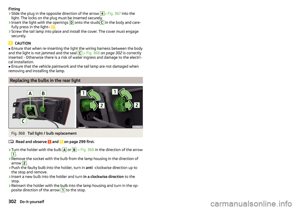
Fitting›Slide the plug in the opposite direction of the arrow 4» Fig. 367 into the
light. The locks on the plug must be inserted securely.›
Insert the light with the openings
D
onto the studs
C
in the body and care-
fully press in the light » .
›
Screw the tail lamp into place and install the cover. The cover must engage
securely.
CAUTION
■ Ensure that when re-inserting the light the wiring harness between the body
and the light is not jammed and the seal C » Fig. 368 on page 302 is correctly
inserted - Otherwise there is a risk of water ingress and damage to the electri-
cal installation.■
Ensure that the vehicle paintwork and the tail lamp are not damaged when
removing and installing the lamp.
Replacing the bulbs in the rear light
Fig. 368
Tail light / bulb replacement
Read and observe
and on page 299 first.
›
Turn the holder with the bulb
A
or
B
» Fig. 368 in the direction of the arrow
1
.
›
Remove the socket with the bulb from the lamp housing in the direction of
arrow
2
.
›
Push the faulty bulb into the holder, turn in anti -clockwise direction up to
the stop and remove.
›
Insert a new bulb into the holder and turn in a clockwise direction to the
stop.
›
Reinsert the holder with the bulb into the lamp housing and turn in the op-
posite direction of the arrow
1
to the stop.
302Do-it-yourself
Page 316 of 336
Selector lever emergency unlocking293
Selector lever lock207
Start and run208
Tiptronic208
Warning light39
Automatic transmission206
AUX90, 150
Settings135
Auxiliary heating (auxiliary heating and ventila- tion)
118
Avoiding damage to your vehicle211
B
Battery Changing batteries for the removable light
292
Changing in key290, 291
Replace the battery in the remote control in the auxiliary heating
291
Belts15
Belt tensioners17
Bluetooth A2DP / AVRCP
133
Name133
on / off133
Paired external devices133
rSAP167
Set140
set to133, 136
Set to133
Switch on/off140
Update131, 134
Updates140
Visibility133, 140
Bluetooth Player151
Bluetooth profile164
Bluetooth® update164
Bonnet Close
269
Open269
Boot Class N1 vehicles109
Boot lid59
Automatic locking59
Contactless open/close61
Open/close59, 60
See boot lid59
Boot lid contactless open/close61
Brake Assist (HBA)214
Brake booster203
Brake fluid273
Check273
specification273
Brake linings Warning light
38
Brake pads new
203
Brake pedal (automatic gearbox) Warning light
38
Brakes Brake booster
203
Brake fluid273
Braking and stabilisation systems212
Information on braking203
Parking brake203
Running in209
Warning light35
Brake system212
Breakdown call168
Broadcasting143
See main menu142
Bulbs Replacing
299
Buttons on the driver door Electric windows
62
C
Call list Call list
170
CameraSee reversing camera221
CAR198
Car battery automatic consumer shutdown
273
Check condition274
Cover274
Disconnecting and reconnecting275
Replacing275
Winter operation274
CAR button198
Car care260
Exterior263
Interior263
Car computer see multifunction display
46
Care and maintenance256
Cargo element106
CAR menu198
Car park184
Carrier112
Car wash260
Exterior263
Panes263
CD149
Central locking53
Problems57
Central locking button55
Changing Batteries for the removable light
292
Battery290, 291
Wheels282
Windscreen wiper blades295
Changing a wheel282
Changing gear Selector lever
207
Tiptronic208
Charging a vehicle battery275
314Index