lifting SKODA SUPERB 2016 3.G / (B8/3V) Owner's Manual
[x] Cancel search | Manufacturer: SKODA, Model Year: 2016, Model line: SUPERB, Model: SKODA SUPERB 2016 3.G / (B8/3V)Pages: 336, PDF Size: 53.89 MB
Page 283 of 336

It is possible to store the reflective vests for the passengers on the rear seat in
the storage compartment in the rear doors.
Fire extinguisher
Fig. 330
Release the fire extinguisher
The fire extinguisher is attached by two straps in a bracket under the front
passenger's seat.
›
To remove the fire extinguisher, release the safety catches on the two belts
in the direction of arrow » Fig. 330and remove the fire extinguisher.
›
To secure , place the fire extinguisher back in the mount and secure with the
belts.
The Owner´s Manual is fitted next to the fire extinguisher.
Pay attention to the expiration date of the fire extinguisher. After this date,
the correct function of the device is not guaranteed.
WARNINGAlways properly secure the fire extinguisher, there is a risk of injury in the
event of sudden braking or a vehicle collision.Vehicle tool kitFig. 331
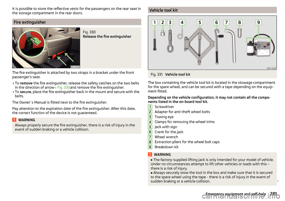
Vehicle tool kit
The box containing the vehicle tool kit is located in the stowage compartment for the spare wheel, and can be secured with a tape depending on the equip-
ment fitted.
Depending on the vehicle configuration, it may not contain all the compo-
nents listed in the on-board tool kit.
Screwdriver
Adapter for anti-theft wheel bolts
Towing eye
Clamps for removing the wheel trims
Jack with sign
Crank for the jack
Wheel wrench
Extraction pliers for the wheel bolt caps
Breakdown kit
WARNING■ The factory-supplied lifting jack is only intended for your model of vehicle.
Under no circumstances attempt to lift other vehicles or loads with this –
there is a risk of injury.■
Always securely stow the tool in the box and make sure that it is secured
to the spare wheel using the tape - there is a risk of injury in the event of
sudden braking or a vehicle collision.
123456789281Emergency equipment and self-help
Page 287 of 336

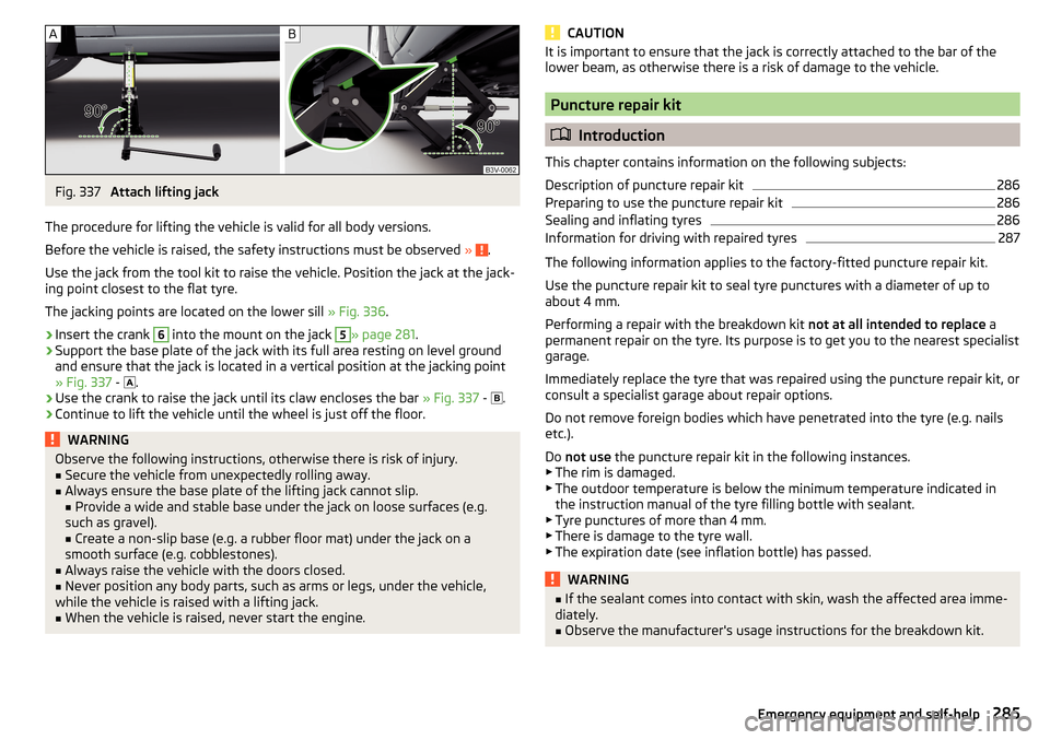
Fig. 337
Attach lifting jack
The procedure for lifting the vehicle is valid for all body versions.
Before the vehicle is raised, the safety instructions must be observed »
.
Use the jack from the tool kit to raise the vehicle. Position the jack at the jack-
ing point closest to the flat tyre.
The jacking points are located on the lower sill » Fig. 336.
›
Insert the crank
6
into the mount on the jack
5
» page 281 .
›
Support the base plate of the jack with its full area resting on level ground
and ensure that the jack is located in a vertical position at the jacking point
» Fig. 337 -
.
›
Use the crank to raise the jack until its claw encloses the bar
» Fig. 337 -
.
›
Continue to lift the vehicle until the wheel is just off the floor.
WARNINGObserve the following instructions, otherwise there is risk of injury.■Secure the vehicle from unexpectedly rolling away.■
Always ensure the base plate of the lifting jack cannot slip.
■ Provide a wide and stable base under the jack on loose surfaces (e.g.
such as gravel). ■ Create a non-slip base (e.g. a rubber floor mat) under the jack on a
smooth surface (e.g. cobblestones).
■
Always raise the vehicle with the doors closed.
■
Never position any body parts, such as arms or legs, under the vehicle,
while the vehicle is raised with a lifting jack.
■
When the vehicle is raised, never start the engine.
CAUTIONIt is important to ensure that the jack is correctly attached to the bar of the
lower beam, as otherwise there is a risk of damage to the vehicle.
Puncture repair kit
Introduction
This chapter contains information on the following subjects:
Description of puncture repair kit
286
Preparing to use the puncture repair kit
286
Sealing and inflating tyres
286
Information for driving with repaired tyres
287
The following information applies to the factory-fitted puncture repair kit.
Use the puncture repair kit to seal tyre punctures with a diameter of up to
about 4 mm.
Performing a repair with the breakdown kit not at all intended to replace a
permanent repair on the tyre. Its purpose is to get you to the nearest specialist
garage.
Immediately replace the tyre that was repaired using the puncture repair kit, or
consult a specialist garage about repair options.
Do not remove foreign bodies which have penetrated into the tyre (e.g. nails etc.).
Do not use the puncture repair kit in the following instances.
▶ The rim is damaged.
▶ The outdoor temperature is below the minimum temperature indicated in
the instruction manual of the tyre filling bottle with sealant.
▶ Tyre punctures of more than 4 mm.
▶ There is damage to the tyre wall.
▶ The expiration date (see inflation bottle) has passed.
WARNING■ If the sealant comes into contact with skin, wash the affected area imme-
diately.■
Observe the manufacturer's usage instructions for the breakdown kit.
285Emergency equipment and self-help
Page 296 of 336

CAUTIONMake sure when lifting not to damage cover parts by the screwdriver in the
shift lever environment.
Replacing windscreen wiper blades
Introduction
This chapter contains information on the following subjects:
Replacing the windscreen wiper blades
294
Replacing the rear window wiper blade
295WARNINGReplace the windscreen wiper blades once or twice a year for safety rea-
sons.
Replacing the windscreen wiper blades
Fig. 353
Setting the service position for
the wiper arms
Fig. 354
Replace windscreen wiper blade
Read and observe on page 294 first.
Before replacing the windscreen wiper blade, put the windscreen wiper arms
into the service position.
Setting the service position
›
Switch the ignition on and off again.
›
Within 10 seconds, push the lever in the direction of arrow » Fig. 353 and
hold for approximately 2 seconds.
Removing the wiper blade
›
Lift the wiper arm from the window in the direction of the arrow
1
» Fig. 354 .
›
Tilt the wiper blade to the stop in the same direction.
›
Hold the wiper arm and press the safety catch
A
in the direction of arrow
2
.
›
Remove the wiper blade in the direction of the arrow
3
.
Attaching the windscreen wiper blade
›
Push the windscreen wiper blade in the opposite direction of the arrow
3
until it locks into place. Check that the windscreen wiper blade is correctly at-
tached.
›
Fold the windscreen wiper arm back to the windscreen.
›
Turn on the ignition and press the lever into the direction of the arrow
» Fig. 353 .
Move the windscreen wiper arms into the home position.
294Do-it-yourself