ESP SKODA YETI 2010 1.G / 5L User Guide
[x] Cancel search | Manufacturer: SKODA, Model Year: 2010, Model line: YETI, Model: SKODA YETI 2010 1.G / 5LPages: 271, PDF Size: 14.71 MB
Page 61 of 271
Lights and Visibility
60
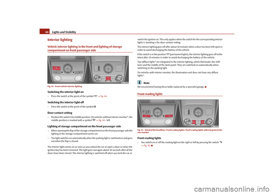
Interior lightingVehicle interior lighting in the front and lighting of storage compartment on front passenger sideFig. 44 Front vehicle interior lightingSwitching the interior light on– Press the switch at the point of the symbol
fig. 44 .
Switching the interior light off– Press the switch at the point of the symbol O.Door contact setting– Position the switch into middle position. On vehicles without interior monitor*, the
middle position is ma rked with a symbol
fig. 44 - left.
Lighting of storage compartment on the front passenger side– When opening the flap of the storage comp artment on the front passenger side the
lighting in the storage compartment comes on.
– The light switches on automatically when the parking light is switched on and goes
out when the flap is closed.
The interior light comes on as soon as you unlock the car or open a door or when the
ignition key has been removed. The light go es out again about 30 seconds after all the
doors have been closed. The interior lighting is switched off when you lock the car or switch the ignition on. This only applies wh
en the switch for the corresponding interior
lights is standing n the door contact setting.
The interior lighting goes off after about 10 minutes when a door has been left open in
order to avoid discharging the battery of the vehicle.
If the switch is in the position
(permanent lights), the interior lighting goes off at the
latest after 10 minutes in order to avoid discharging the battery of the vehicle.
Two diffuse lights* are integrated in the in terior lighting, which illuminates the shift
lever and the middle of the dash panel. They are switched on automatically when
switching on the parking light.
On vehicles with interior monitor, the il lumination unit does not have any diffuse
lights*.
Note
We recommend having these bulbs re placed by a specialist garage.Front reading lightsFig. 45 Detail of the headliner: Front reading lights / front reading lights with integrated inte-
rior monitorFront reading lights– You switch on or off the reading light on the right or left by pressing the switch
fig. 45 .
s2ug.6.book Page 60 Friday, April 9, 2010 2:24 PM
Page 65 of 271
Lights and Visibility
64
The windscreen wipers and the wash system only operate if the ignition is switched on
and the bonnet is closed
9).
The rear window wiper operates only if the boot lid is closed.
If the intermittent wipe is switched on, the intervals are also controlled depending on
speed.
The rain sensor* automatically regulates the break between the individual wiper
strokes depending on the intensity of the rain.
The rear window will be wiped again if the front window wipers are on when reverse
gear is selected.
The windscreen washer nozzles are heated* when the ignition is switched on.
Top up with wash liquid page 214.
Winter position
If the windscreen wipers are in rest positi on, they cannot be folded out from the wind-
screen. For this reason we recommend adjusting the windscreen wipers in winter so
that they can be folded out from the windscreen easily. You can set this rest position as
follows:
Switch on the windscreen wipers.
Switch off the ignition. The windscreen wipers remain in the position in which they
were when switching off the ignition.
You can also use the service position page 65 as a winter position.
WARNING
Properly maintained wind screen wiper blades are essential for clear visi-
bility and safe driving page 65.
Do not use the windscreen washer sy stem at low temperatures, without
heating the windscreen beforehand. Otherwise the window cleaner could
freeze on the windscreen and re strict the view to the front.
The rain sensor only operates as a su pport. The driver is not released from
the responsibility to set the function of the windscreen wipers manually
depending on the visibility conditions.Caution
In frosty weather, please firs t of all check whether the windscreen wiper blades are not
frozen to the windscreen before switching them on. Switching on windscreen wipers
when the blades are frozen to the windscreen may result in damage both to the blades
and the motor of the windscreen wipers!
Note
If the slower page 63, fig. 50 or the faster wiper setting is switched on and
the vehicle speed decreases to below 4 km/h, the lower wiper step is switched on
automatically. At a speed increase of more than 8 km/h the previous wiper setting is
established again.
If there is an obstacle on the windscre en, the wiper will try to push away the
obstacle. If the obstacle continues to bloc k the wiper, the wiper stops automatically
after 5 attempts to eliminate the obstacle, in order to avoid a damage to the wiper.
Remove the obstacle and and switch on the wiper again.
The content of the windscreen wiper reserv oir is 3 litres. On vehicles which are
equipped with a headlight cleani ng system*, the content of the reservoir is 5.5 litres.
On vehicles fitted with auxiliary heating, the content of the windscreen wiper reservoir
is 4.5 litres.
Automatic rear window wiper*If the windshield wiper lever is in the posi tion or , the rear window wiper carries
out a wiping process every 30 seconds or 10 seconds at a speed above 5 km/h.
When the rain sensor* is active (the lever is in the position ) the function is only
active if the front window wipers continue to operate (no break between each wiping
process).
9)On vehicles which do not have a contact switch for the bonnet, the windshield wiper and wash
system operates also when the bonnet is opened.
WARNING (continued)
A2
A3
A2
A3
A1
s2ug.6.book Page 64 Friday, April 9, 2010 2:24 PM
Page 72 of 271
Seats and Stowage71
Using the system
Safety
Driving Tips
General Maintenance
Breakdown assistance
Technical Data
The seat backrests must not be angled too far back when driving otherwise
this will affect proper operation of the se at belts and of the airbag system - risk
of injury!Note
If the movement of the seat is inadverten tly interrupted during an adjustment, once
again press the switch in the appropriate di rection and continue with the adjustment
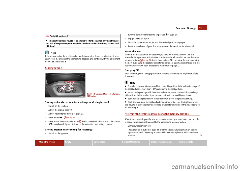
of the seat to the end.Storing settingStoring seat and exterior mirror settings for driving forward– Switch on the ignition.
– Adjust the seat page 70.
– Adjust both exterior mirrors page 67.
– Press button SET fig. 57 .
– Press one of the memory buttons with in 10 seconds after pressing the button
SET - an acknowledgement signal confirms that the seat setting is stored.Storing exterior mirror setting for reversing*– Switch on the ignition. – Turn the exterior mirror control to position
page 67.
– Engage the reverse gear.
– Move the right exterior mirror into the desired position page 67.
– Take the vehicle out of gear. The set posi tion of the exterior mirror is stored.
Memory buttons
Memory for the seat offers the possibility to store the individual driver seat and
external mirror position. An individual posi tion can be allocated to each of the three
memory buttons fig. 57, that is three in total. Af ter pressing the corresponding
memory button , the seat and the exterior mirror are automatically moved into the
positions which have been allocated to this button page 71.
Emergency Off
You can interrupt the setting operation at any time, if you operate any button of the
driver seat.
Note
For safety reasons, it is not possible to store this position if the inclination angle of
the seat backrest is more than 102° in relation to the seat cushion.
When storing settings with the memory buttons, we recommend that you begin
with the front button and assign a memory button to each additional driver.
Each new setting stored with the same button erases the previous setting.
Each time you store the seat and exterior mirror settings for driving forward you
also have to re-store the individual setting of the exterior mirror on the passenger side
for reversing.
Assigning the remote control key to the memory buttonsAfter storing the settings of the seat and exterior mirrors, you have 10 seconds in order
to assign the radio remote control to the appropriate memory button.
– Withdraw the ignition key.
– Press the unlock button page 44, after the successful assignment an audible
signal will sound. The setting is stored with the memory button which you have
selected.
WARNING (continued)
Fig. 57 Driver seat: Memory buttons and
SET button
AA
AB
ABAB
s2ug.6.book Page 71 Friday, April 9, 2010 2:24 PM
Page 75 of 271
Seats and Stowage
74
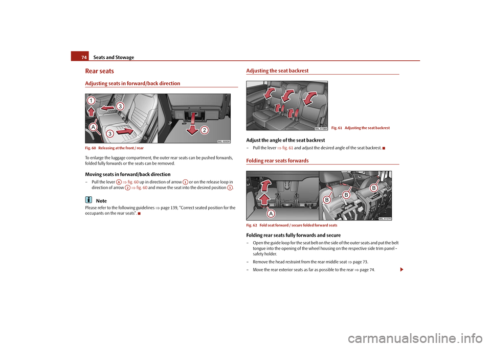
Rear seatsAdjusting seats in forward/back directionFig. 60 Releasing at the front / rearTo enlarge the luggage compartment, the ou ter rear seats can be pushed forwards,
folded fully forwards or the seats can be removed.Moving seats in forward/back direction– Pull the lever fig. 60 up in direction of arrow or on the release loop in
direction of arrow fig. 60 and move the seat into the desired position .
Note
Please refer to the following guidelines page 139, “Correct seated position for the
occupants on the rear seats”.
Adjusting the seat backrestAdjust the angle of the seat backrest– Pull the lever fig. 61 and adjust the desired an gle of the seat backrest.Folding rear seats forwardsFig. 62 Fold seat forward / secure folded forward seatsFolding rear seats fully forwards and secure– Open the guide loop for the seat belt on the side of the outer seats and put the belt
tongue into the opening of the wheel housing on the respective side trim panel -
safety holder.
– Remove the head restraint from the rear middle seat page 73.
– Move the rear exterior seats as far as possible to the rear page 74.
AA
A1
A2
A3
Fig. 61 Adjusting the seat backrest
s2ug.6.book Page 74 Friday, April 9, 2010 2:24 PM
Page 79 of 271
Seats and Stowage
78
Do not place any footmats or other additional floor coverings in the area of
the pedals in order to ensure that all the pedals can be fully depressed and are
able to return unobstructed to their initial position - risk of accident!
There must be no objects on the floor which could roll under the pedals. You
would then no longer be able to apply the brakes, operate the clutch or acceler-
ator - risk of accident!
luggage compartmentLoading the luggage compartmentPlease observe the following in the interest of having good handling characteristics of
your vehicle:
– Distribute the items of luggage as evenly as possible.
– Place heavy objects as far forward as possible.
– Attach the items of luggage to the lashing eyes or the fixing net* page 79.
In the event of an accident, there is such a high kinetic energy which is produced by
small and light objects that they can cause se vere injuries. The magnitude of the kinetic
energy depends on the speed at which the vehi cle is travelling and on the weight of the
object. The speed at which the vehicle is travelling is in this case the more significant
factor.
Example: In the event of a frontal collision at a speed of 50 km/h, an unsecured object
with a weight of 4.5 kg produces an ener gy, which corresponds to 20 times its own
weight. This means that it results in a weight of approx. 90 kg. You can imagine the inju-
ries that can occur, if this “bullet” is fl ying through the interior compartment and hits
an occupant.
WARNING
Store the objects in the luggage compartment and attach them to the
lashing eyes, e.g. with the fixing nets.
Loose objects in the passenger compartment can be thrown forward during
a sudden manoeuvre or in case of an a ccident and can injure the occupants or
other oncoming traffic. This risk is still increased, if the objects which are flying
around are hit by a deployed airbag. In this case, the objects which are thrown
back can injure the occupants - hazard.
Please note that the handling properti es of your vehicle may be affected
when transporting heavy objects as a result of the displacement of the centre of
gravity. The speed and style of driv ing must be adjusted accordingly.
The items carried in the luggage compartment should be stowed in such a
way that no objects are able to slip forward if there are any sudden driving or
braking manoeuvres undertaken - risk of injury!
Never drive with the boot lid fully opened or slightly ajar otherwise exhaust
gases may get into the interior of the vehicle - risk of poisoning!
On no account exceed the permissible axle loads and the permissible gross
weight of the vehicle - risk of accident!
Never transport occupants in the luggage compartment!Note
Tyre pressure must be adjusted to the load page 216.Vehicles of category N1On vehicles of the category N1, which are not fitted with a protective grille, a lashing
set which complies with the standard EN 12195 (1 - 4) must be used for fastening the
load.
WARNING (continued)
WARNING (continued)
s2ug.6.book Page 78 Friday, April 9, 2010 2:24 PM
Page 102 of 271
Heating and air conditioning system101
Using the system
Safety
Driving Tips
General Maintenance
Breakdown assistance
Technical Data
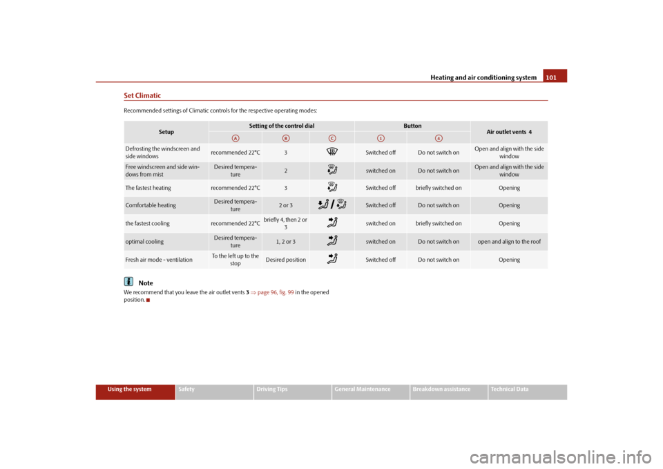
Set ClimaticRecommended settings of Climatic controls for the respective operating modes:
Note
We recommend that you leave the air outlet vents 3 page 96, fig. 99 in the opened
position.
Setup
Setting of the control dial
Button
Air outlet vents 4
Defrosting the windscreen and
side windows
recommended 22°C
3
Switched off
Do not switch on
Open and align with the side
window
Free windscreen and side win-
dows from mist
Desired tempera-ture
2
switched on
Do not switch on
Open and align with the side window
The fastest heating
recommended 22°C
3
Switched off
briefly switched on
Opening
Comfortable heating
Desired tempera-ture
2 or 3
Switched off
Do not switch on
Opening
the fastest cooling
recommended 22°C
briefly4, then 2or
3
switched on
briefly switched on
Opening
optimal cooling
Desired tempera-ture
1, 2 or 3
switched on
Do not switch on
open and align to the roof
Fresh air mode - ventilation
To the left up to the stop
Desired position
Switched off
Do not switch on
Opening
AA
AB
AC
A1
A4
s2ug.6.book Page 101 Friday, April 9, 2010 2:24 PM
Page 105 of 271
Heating and air conditioning system
104
Switching cooling on and offSwitching cooling on and off–Press the button page 103, fig. 103 . The warning light lights up in the button.
– When you again press the switch , the cooling system is switched off. The warning light in the button goes out. Only the function of the ventilation remains
active when no lower temperature than the outside temperature can be reached.Setting temperatureYou can separate the interior temperature for the left and right side separately.
– You can set the temperature for both sides after switching on the ignition with the
control dial .
– If you wish to set the temperature for the right side, turn the control dial . The warning light in the button lights up, this indicates that differing tempera-
tures for the left and right side can be set.
If the warning light in the button lights up, the temperature for both sides
cannot be set with the control dial . You can reinitiate this function by pressing the
button . The warning light in the button which indicates the possibility to set
differing temperatures for the left and right side, goes out.
You can set the interior temperature between +18°C and +26°C. The interior temper-
ature is regulated automatically within this range. If you chose a temperature lower
than +18°C, a blue symbol lights up at the start of the numerical scale. If you chose a
temperature higher than +26°C, a red symbol lights up at the end of the numerical
scale. In both limit positions the Climatroni c operates at maximum cooling or heating
capacity, respectively. The temperatur e is not controlled in this case.
Lengthy and uneven distri bution of the air flow out of the vents (in particular at the leg
area) and large differences in temperature, for example when getting out of the vehicle,
can result in chills in sensitive persons.
Recirculated air mode
In recirculated air mode air is sucked out of the interior of the vehicle
and then fed back into the interior. When the automatic air distribution
control is switched on, an air quality sensor measures the concentration
of pollutants in the drawn-in air.Recirculated air mode prevents polluted air outside the vehicle from getting into the
vehicle, for example when driving through a tunn el or when standing in a traffic jam. If
a considerable increase in concentration of pollutants is recognized by the air quality
sensor, when the automatic air distribution co ntrol is switched on, the air distribution
control will temporarily be switched off. If the concentration of pollutants decreases to
the normal level, the air distribution control is automatically switched off so that fresh
air can be guided into the vehicle interior.Switching recirculated air mode on– Press the button repeatedly until the warning light on the left side of the
button lights up.Switch on automatic air distribution control– Press the button repeatedly until the warning light on the right side of the
button lights up.Switch off automatic air distribution control temporarily– If the air quality sensor does not switch on the air distribution control automatically
when there is a nauseating smell, you can switch it on yourself by pressing the
button *. The warning light lights up in the button on the left side.Switching recirculated air mode off– Press the button or press the button repetitively, until the warning
lights in the button go out.
WARNING
You should not leave recirculated air mode on over a longer period of time, as
“stale” air may result in fatigue in the driver and occupants, divert your atten-
AC
AC
A7
A14
DUALDUALA7
DUAL
AUTO
s2ug.6.book Page 104 Friday, April 9, 2010 2:24 PM
Page 106 of 271
Heating and air conditioning system105
Using the system
Safety
Driving Tips
General Maintenance
Breakdown assistance
Technical Data
tion and also cause the windows to mist up. The risk of having an accident
increases. Switch recirculated air mode off as soon as the windows begin
misting up.
Note
If the windscreen mists up, press the button
page 103, fig. 103 . After
the windscreen has been demisted, press the button .
The automatic air distribution control operates only if the outside temperature is
higher than approx. 2°C.
Controlling blower
There are a total of seven blower stages available.The Climatronic system controls the blower st ages automatically in line with the inte-
rior temperature. You can also , however, a dapt the bl ower stages ma nua lly to suit y our
particular needs.
– Press again the button on the left side (reduce blower speed) or on the right side (increase blower speed).
If you switch off the blower, the Climatronic is switched off.
The set blower speed is displayed above the button when the respective number
of warning lights come on.
WARNING
“Stale air” may result in fatigue in the driver and occupants, reduce atten-
tion levels and also cause the windows to mist up. The risk of having an accident
increases.
Do not switch the Climatronic system off for longer than necessary.
Switch the Climatronic system on as soon as the windows mist up.
Defrosting windscreenDefrosting windscreen - switching on– Press the button page 103, fig. 103 .Defrosting windscreen - switching off– Once again press the button or the button .
The temperature control is controlled automatically. More air flows out of the air outlet
vents 1 and 2.Auxiliary heating (auxiliary heating and ventilation)*Description and important information
The auxiliary heating (auxiliary he ating and ventilation) heats or
supplies the interior of the vehicl e with fresh air independent of the
engine.Auxiliary heating (auxiliary heating)
The auxiliary heating (auxiliary heating) functions in connection with the Climatic or
Climatronic.
It can be used when stationary, when engi ne is switched off for preheating of the
vehicle as well as while driving (only during the heating phase of the engine).
The engine is also preheated when the vehicle is stationary and the engine is switched
off, if the auxiliary heating is switched on.
The auxiliary heating (auxiliary heating) wa rms up the coolant during the combustion
of fuel from the vehicle tank. The coolant warms up the air, which (if the blower speed
is not set to zero) flows into the occupant compartment.
Auxiliary ventilation
The auxiliary ventilation enables fresh air to flow into the vehicle interior by switching
off the engine, whereby the interior temperature is effectively decreased (e.g. with the
vehicle parked in the sun).
WARNING (continued)
A1AUTO
AUTO
s2ug.6.book Page 105 Friday, April 9, 2010 2:24 PM
Page 115 of 271
Starting-off and Driving
114
set so that the play function volume decr eases when activating the parking aid, see
Owner's Manual radio* or na vigation system*. This improves the audibility of the
parking aid.
Activating
The parking aid is activated when the reverse gear is engaged and the ignition is
turned on or by pressing the button page 113, fig. 110 - the symbol lights up in
the button. The activation is confirmed by a brief acknowledgement signal.
Deactivating
The parking aid is deactivated after pressing the button° page 113, fig. 110 or at
a speed of more than 10 km/h - the symbol
in the button is no longer illuminated.
WARNING
The parking aid is not a substitute for the driver paying proper attention and
it is always the driver's responsibility to take care when reversing the vehicle or
carrying out similar manoeuvres.
You should therefore satisfy yourself, befo re reversing, that there is no small
obstacle, such as a rock, thin post, trailer drawbar etc., in front or behind your
vehicle. Such an obstacle might not be within the range detected by the sensors.
Under certain circumstances, surfaces of certain objects and types of
clothing cannot reflect the signal of the parking aid. Thus, these objects or
people who wear such clothing are not recognised by the sensors of the parking
aid.Note
Only the front parking aid operates if yo u are towing a trailer (applies only to
models which feature a factory-fitted towing device*).
If a warning signal sounds for about 3 seco nds after activating the system and there
is no obstacle close to your vehicle, this indicates a system fault. The fault is confirmed
additionally when the symbol flashes in the button page 113, fig. 110 . Have the
fault rectified by a specialist workshop.
The sensors must be kept clean and free of ice to enable the parking aid to operate
properly.
If the parking aid is activated and the sele ctor lever of the automatic gearbox is in
the position , warning signal indicates inte rruption (vehicle can no longer move).
Park Assist*Description and important informationThe park assist assists you when parking in a suitable parallel parking space between
two vehicles or behind a vehicle.
The park assist automatically searches for suitable parking spaces after switching on
the ignition and when driving up to 30 km/h.
During the parking procedure the park assist only takes over the steering movements,
the pedals continue to be operated by the driver.
Function of the system is based on:
Length and depth measurement of the parking spaces when driving
Evaluation of the size of the parking space
Definition of the correct position of the vehicle for parking
Calculating the line on which the vehicle drives backwards into the parking space
Actuation of the steering force assistance, automatic spinning of the wheels of the
front axle when parking.
WARNING
The park assist does not take away th e responsability from the driver when
parking.
Pay particular attention to small children and animals as they would not be
recognised by the sensors of the parking aid.
Under certain circumstances, surfaces of certain objects and types of
clothing cannot reflect the signal of the park assist or the parking aid. Thus,
these objects or people who wear such clothing are not recognised by the
sensors of the parking aid.
AP
s2ug.6.book Page 114 Friday, April 9, 2010 2:24 PM
Page 116 of 271
Starting-off and Driving115
Using the system
Safety
Driving Tips
General Maintenance
Breakdown assistance
Technical Data
The external sound source of the park assist and the parking aid can be
disruptively influenced and under unfavourable conditions, objects or people
cannot be recognised by the sensors of the parking aid.Caution
If other vehicles are parked behind or on the kurb, the park assist guides your
ve hicle be yond the kurb or onto it. Make s ure that the whee ls or the whe el rims of yo ur
vehicle are not damaged and if necessary intervene in time.
You should satisfy yourself before parking that there is no small obstacle, such as a
rock, thin post, trailer drawbar etc., in front or behind your vehicle. Such an obstacle
might not be within the range detected by the sensors.
Under certain circumstances, surfaces or st ructures of certain objects such as wire
mesh fences, powder snow etc..., ca nnot be recognised by the system.
The evaluation of the parking space and the parking procedure depends on the
circumference of the wheels. The system does not function correctly if your vehicle is
mounted with wheels of non-permissible size, snow chains or a temporary spare
wheel (in order to reach the nearest workshop). If the tyres other than those excepted
by the manufacturer are mounted, the resulting position of the vehicle in the parking
space can differ slightly. The parking assistant system automatically performs the
correction of the wheel circumference when driving.
The accuracy of the evaluation for the parking space can be influenced by the
incorrectly determined outside temperature if the later is influenced by the thermal
radiation of the engine i.e for stop and go in a traffic jam.
In order to avoid damaging th e sensors while cleaning with high-pressure cleaners
or steam jets, the sensors must only be directly sprayed for short periods while a
minimum distance of 10 cm must be observed.Note
A component of the park assist is the front and rear parking aid*.
The electronic stability programme (ESP*) must always be switched on for the
parking procedure.
Only the front parking aid operates if you are towing a trailer (applies only to
models which feature a factory-fitted towing device*). This is why it is not possible to
park backwards with the help of the park assist when towing a trailer.
The sensors must be kept clean and free of ice to enable the parking aid to operate
properly.
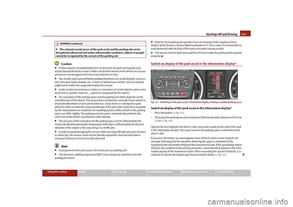
Switch on display of the park a ssist in the information display*Fig. 111 Switching on the park assist / inform ation display: Finding a suitable parking spaceSwitch on display of the park assist in the information display*– Press the button fig. 111 .
– Drive past the parking row up to maximum 30 km/h and with a distance of 0.5 m to 1.5 m fig. 111 .
Operate the turn signal for the driver's side if you wish to park on this side of the road.
In the information display* the search area for the parking space is indicated on the
driver's side.
If you press the button at a speed greate r than 30 km/h and less than 50 km/h, the
message indicating that the speed for detecting the space is exceeded will be
displayed in the information display of the in strument cluster. If the speed drops below
30 km/h, the condition of the parking assistant is automatically displayed in the infor-
mation display of the instrument cluster. When exceeding the speed of 50 km/h, it is
required to activate the displa y again by pressing the button fig. 111 .
WARNING (continued)
s2ug.6.book Page 115 Friday, April 9, 2010 2:24 PM