stop start SKODA YETI 2010 1.G / 5L Owner's Guide
[x] Cancel search | Manufacturer: SKODA, Model Year: 2010, Model line: YETI, Model: SKODA YETI 2010 1.G / 5LPages: 271, PDF Size: 14.71 MB
Page 192 of 271
Towing a trailer191
Using the system
Safety
Driving Tips
General Maintenance
Breakdown assistance
Technical Data
Headlights
Before starting off with a hitched trailer, also check the setting of the headlights. Alter
the setting as necessary with the ai
d of the headlight beam adjuster page 58.
Detachable ball head
The ball rod is detachable on vehicles which feature a factory-fitted towing device. It is
stowed together with separate fitting instru ctions in the spare wheel well in the luggage
compartment of the vehicle.
Further information on the towing device page 192.
Note
We recommend that you also have your vehicle inspected between service inter-
vals if you tow a trailer frequently.
The handbrake on the towing vehicle must be put on when coupling and decou-
pling the trailer.
Driving Tips
Particular caution is required when towing a trailer.– Do not, as far as possible, drive with your vehicle unladen and the trailer laden.
– Do not make full use of the legal maximum speeds. This applies in particular to downhill sections.
– Apply the brakes in good time.
– Keep a check on the coolant temperature gauge if the outside temperature is high.
Distribution of weight
The distribution of the weight is very poor if your vehicle is unladen and the trailer is
laden. Maintain a particularly low speed if you cannot avoid driving with this combina-
tion.
Driving speed
Do not drive faster than 80 km/hour for safety reasons. This also applies for countries
in which higher speeds are allowed. The fact that the driving stability of the vehicle + trailer combination reduces with
increasing speed means that the legally allowed speed should not be used when there
are unfavourable road, weather or wind cond
itions, particularly near accident black
spots.
You must always reduce your speed immediat ely as soon as you detect even just the
slightest swaying of the trailer. On no account attempt to stop the trailer from
“swaying” by accelerating.
Apply the brakes in good time! If the trailer is fitted with a trailer brake, apply the
brakes gently at first and then brake firmly. This will avoid brake jolts resulting from the
trailer wheels locking. Shift down gears in good time before negotiating a downhill
section to allow the engine to also act as a brake.
Engine overheating
Please keep a check on the coolant temperature gauge if you have to negotiate a
lengthy slope in a low gear at a high engi ne speed when the outside temperature is
very high page 17, “Coolant temperature gauge”.
If the needle of the coolant temperature gauge moves into the right-hand area or even
the red area of the scale, reduce your speed immediately. Stop and switch off the
engine if the warning light
in the instrument cluster begins flashing. Wait a few
minutes and check the level of coolant in the coolant expansion bottle page 208,
“Inspecting the coolant level”.
Please refer to the following guidelines page 33, “Coolant temperature/ Coolant
quantity ”.
The coolant temperature can be reduced by switching on the heating.
Any increase in the cooling effect of the coolant fan through shifting down a gear and
increasing the engine speed is not possible since the fan speed is independent of the
engine speed. One should also not drop a gear for this reason when towing a trailer as
long as the engine can manage th e slope without any drop in speed.
s2ug.6.book Page 191 Friday, April 9, 2010 2:24 PM
Page 205 of 271
Inspecting and replenishing
204Caution
Never open the bonnet using the locking lever - danger of causing damage.
Ensure that the arms of the windscreen wipers are correctly in place against the
windscreen before opening the bonnet otherwise damage could occur to the
paintwork.
Working in the engine compartment
Particular care is required when carrying out any work in the engine
compartment!There is a risk of injuries, scalding, acci dents and fire when working in the engine
compartment, e.g. inspecting and replenishing oil and other fluids. For this
reason, it is essential to comply with the warning instructions stated below and
with the general applicable rules of safe ty. The engine compartment of your car
is a hazardous area .
WARNING
Never open the bonnet if you see that steam or coolant is flowing out of the
engine compartment - risk of scalding! Wait long enough until the steam or
coolant has stopped escaping.
Switch off the engine and pull out the ignition key.
Apply the handbrake firmly.
If your vehicle is fitted with a manual gearbox, move the gearshift lever into
Neutral, or if it is fitted with automatic gearbox, move the selector lever into
position P.
Allow the engine to cool down.
Keep children clear of the engine compartment.
Never spill oil and other fluids over the hot engine. Such fluids (e.g. the anti-
freeze contained in the coolant) may ignite!
Avoid short circuits in the electrical system - particularly on the battery.
Never place your hand into the radiator fan as long as the engine is still
warm. The fan might suddenly start running!
Never open the cap of the coolant expansion bottle as long as the engine is
still warm. The cooling system is pressurized!
Cover over the cap of the coolant expansion reservoir with a large cloth
when opening it as protection for your face, hands and arms from hot steam or
hot coolant.
Do not let objects, such as e.g cleaning cloth or tools lie in the engine
compartment.
If you wish to work under the vehicl e, you must secure the vehicle from
rolling away and support it with suitable supporting blocks: the car jack is not
sufficient for this - risk of injury!
In cases where it be necessary to carry out inspection work when the engine
is running there is an additional risk fr om rotating parts (e.g. the V-ribbed belt,
alternator, radiator fan) and from the high-voltage ignition system. Please
observe in addition the following:
Never touch the electrical cabl es of the ignition system.
Absolutely avoid any jewellery, loose it ems of clothing or long hair from
getting into the rotating parts of the engine - Hazard! Therefore remove any
jewellery beforehand, tie up your hair and wear tight fitting clothing.
Please also comply with the warnin g instructions stated below when
carrying out any essential work on the fuel system or on th e electrical system:
Always separate the car battery from the electrical system.
Do not smoke.
Never carry out any work close to naked flames.
Always keep a working fire extinguisher at hand.Caution
When replenishing fluids in the engine, always ensure that the fluids are on no account
mixed up. This may result in major oper ating problems and also vehicle damage!
WARNING (continued)
s2ug.6.book Page 204 Friday, April 9, 2010 2:24 PM
Page 232 of 271
Breakdown assistance231
Using the system
Safety
Driving Tips
General Maintenance
Breakdown assistance
Technical Data
Front towing eye
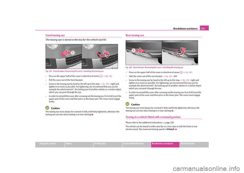
The towing eye is stored in the box for the vehicle tool kit.Fig. 182 Front bumper: Removing the cover / installing the towing eye– Press on the upper half of the cover in direction of arrow fig. 182 .
– Pull the cover out of the front bumper.
– Screw in the towing eye by hand to the left up to the stop fig. 182 - right and
tighten it as much as possible. For ti ghtening, we recommend that you use for
example the wheel wrench*, the lashing eye of another vehicle or a similar object
which you can push through the eye.
– In order to reinstall the cover after screwing out the towing eye, first of all insert the upper part of the cover and then press in the lower part. The cover must engage
firmly.
Caution
The towing eye must always be screwed in fully and firmly tightened, otherwise the
towing eye can tear when to wing in or tow-starting!
Rear towing eyeFig. 183 Rear bumper: Removing the cover / installing the towing eye– Press on the upper half of the cover in direction of arrow fig. 183 .
– Take the cover out of the rear bumper fig. 183 - left.
– Screw in the towing eye by hand to the left up to the stop fig. 183 - right and
tighten it as much as po ssible. For tightening, we recommend that you use for
example the wheel wrench*, the lashing eye of another vehicle or a similar object
which you can push through the eye.
– In order to reinstall the cover after screwing out the towing eye, first of all insert the
upper part of the cover and then press in the lower part. The cover must engage
firmly.
Caution
The towing eye must always be screwed in fully and firmly tightened, otherwise the
towing eye can tear when towing in or tow-starting!Towing in a vehicle fitted with a manual gearboxPlease refer to the additional instructions page 230.
The vehicle can be towed in with a tow bar or a tow rope or with the front or rear
wheels raised. The maximum towing speed is 50 km/h.
A1
A1
s2ug.6.book Page 231 Friday, April 9, 2010 2:24 PM
Page 235 of 271
Fuses and light bulbs
234
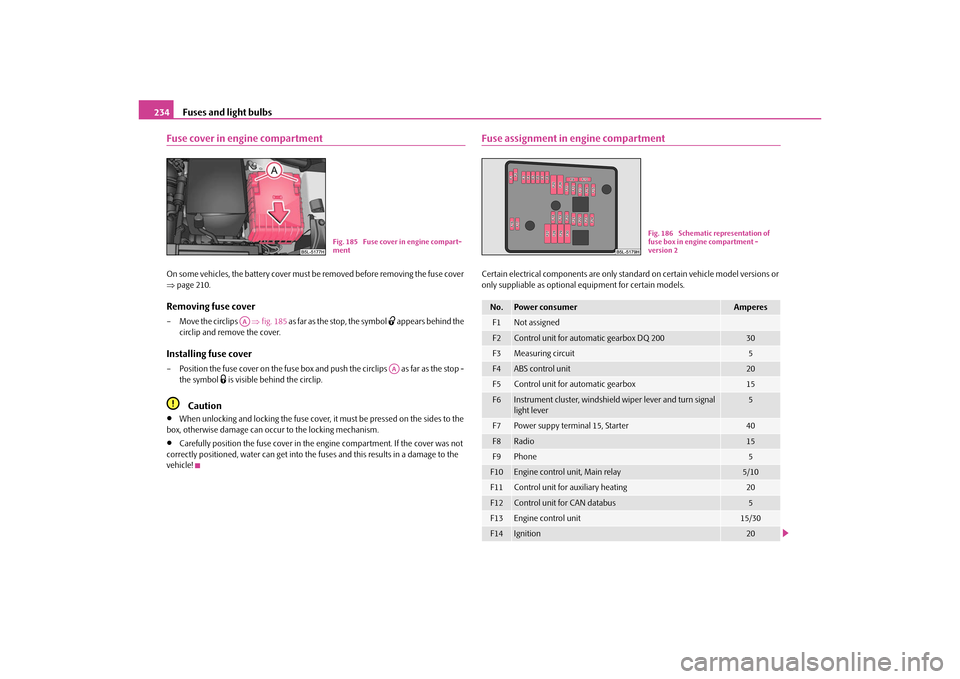
Fuse cover in engine compartmentOn some vehicles, the battery cover must be removed before removing the fuse cover
page 210.Removing fuse cover– Move the circlips fig. 185 as far as the stop, the symbol
appears behind the
circlip and remove the cover.
Installing fuse cover– Position the fuse cover on the fuse box and push the circlips as far as the stop -
the symbol
is visible behind the circlip.
Caution
When unlocking and locking the fuse cover, it must be pressed on the sides to the
box, otherwise damage can occur to the locking mechanism.
Carefully position the fuse cover in the engine compartment. If the cover was not
correctly positioned, water can get into the fuses and this results in a damage to the
vehicle!
Fuse assignment in engine compartmentCertain electrical components are only stan dard on certain vehicle model versions or
only suppliable as optional equipment for certain models.
Fig. 185 Fuse cover in engine compart-
ment
AA
AA
No.
Power consumer
Amperes
F1
Not assigned
F2
Control unit for automatic gearbox DQ 200
30
F3
Measuring circuit
5
F4
ABS control unit
20
F5
Control unit for automatic gearbox
15
F6
Instrument cluster, windshield wiper lever and turn signal
light lever
5
F7
Power suppy terminal 15, Starter
40
F8
Radio
15
F9
Phone
5
F10
Engine control unit, Main relay
5/10
F11
Control unit for auxiliary heating
20
F12
Control unit for CAN databus
5
F13
Engine control unit
15/30
F14
Ignition
20
Fig. 186 Schematic representation of
fuse box in engine compartment -
version 2
s2ug.6.book Page 234 Friday, April 9, 2010 2:24 PM
Page 237 of 271
Fuses and light bulbs
236
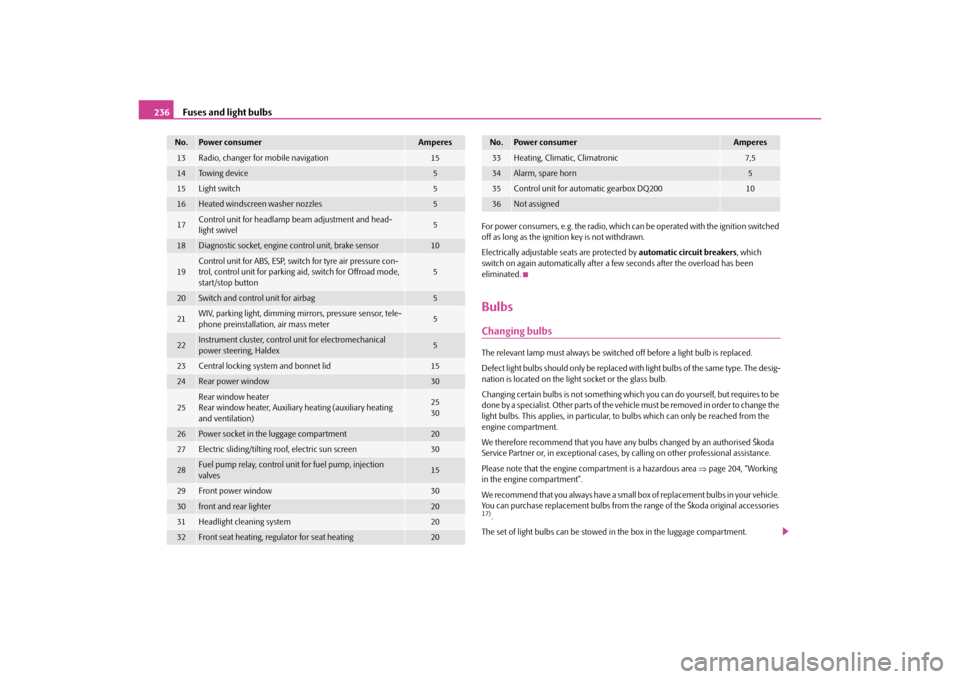
For power consumers, e.g. the radio, which ca n be operated with the ignition switched
off as long as the ignition key is not withdrawn.
Electrically adjustable seats are protected by automatic circuit breakers, which
switch on again automatically after a few seconds after the overload has been
eliminated.BulbsChanging bulbsThe relevant lamp must always be switch ed off before a light bulb is replaced.
Defect light bulbs should only be replaced with light bulbs of the same type. The desig-
nation is located on the light socket or the glass bulb.
Changing certain bulbs is not something whic h you can do yourself, but requires to be
done by a specialist. Other parts of the vehi cle must be removed in order to change the
light bulbs. This applies, in particular, to bulbs which can only be reached from the
engine compartment.
We therefore recommend that you have any bulbs changed by an authorised Škoda
Service Partner or, in exceptional cases, by calling on other professional assistance.
Please note that the engine compartment is a hazardous area page 204, “Working
in the engine compartment”.
We recommend that you always have a small box of replacement bulbs in your vehicle.
You can purchase replacement bulbs from th e range of the Škoda original accessories 17).
The set of light bulbs can be stowed in the box in the luggage compartment.
13
Radio, changer for mobile navigation
15
14
To w i n g d e v i c e
5
15
Light switch
5
16
Heated windscreen washer nozzles
5
17
Control unit for headlamp beam adjustment and head-
light swivel
5
18
Diagnostic socket, engine control unit, brake sensor
10
19
Control unit for ABS, ESP, switch for tyre air pressure con-
trol, control unit for parking aid, switch for Offroad mode,
start/stop button
5
20
Switch and control unit for airbag
5
21
WIV, parking light, dimming mirrors, pressure sensor, tele-
phone preinstallation, air mass meter
5
22
Instrument cluster, control unit for electromechanical
power steering, Haldex
5
23
Central locking system and bonnet lid
15
24
Rear power window
30
25
Rear window heater
Rear window heater, Auxiliar y heating (auxiliary heating
and ventilation)
25
30
26
Power socket in the luggage compartment
20
27
Electric sliding/tilting roof, electric sun screen
30
28
Fuel pump relay, control unit for fuel pump, injection
valves
15
29
Front power window
30
30
front and rear lighter
20
31
Headlight cleaning system
20
32
Front seat heating, regulator for seat heating
20
No.
Power consumer
Amperes
33
Heating, Climatic, Climatronic
7,5
34
Alarm, spare horn
5
35
Control unit for automatic gearbox DQ200
10
36
Not assigned
No.
Power consumer
Amperes
s2ug.6.book Page 236 Friday, April 9, 2010 2:24 PM