check engine SKODA YETI 2012 1.G / 5L Owner's Guide
[x] Cancel search | Manufacturer: SKODA, Model Year: 2012, Model line: YETI, Model: SKODA YETI 2012 1.G / 5LPages: 225, PDF Size: 5.47 MB
Page 197 of 225

WARNING (Continued)
■ Do not drive faster than 80 km/h (50 mph).
■ Avoid accelerating at full throttle, sharp braking and fast cornering.
■ Check the tyre inflation pressure after driving for 10 minutes!
■ The sealant is hazardous to heath. Remove immediately if it comes into con-
tact with the skin. For the sake of the environment
Used sealant or sealant whose expiry date has passed must be disposed of in ac-
cordance with environmental protection regulations. Note
■ Observe the manufacturer's usage instructions for the breakdown kit.
■ A new bottle of sealant can be purchased from ŠKODA Original Accessories.
■ Immediately replace the wheel that was repaired using the breakdown kit or
consult a ŠKODA specialist garage about repair possibilities. ÐComponents of the breakdown kit
Fig. 160
Components of the breakdown kit
First read and observe the introductory information and safety warn-
ings on page 194.
ä The breakdown kit contains the following parts:
Valve remover
Sticker with speed designation
“max. 80 km/h”/“max. 50 mph”
Inflation hose with plug
Air compressor
Tyre inflation hose
Tyre inflation pressure indicator
Air release valve
ON and OFF switch
12 volt cable connector
Tyre inflator bottle with sealing agent
Replacement valve core
The valve remover 1
has a slot at its lower end which fits into the valve core.
This is the only way in which you can remove and re-install the valve core from
the tyre valve. The same also applies to the replacement valve core 11
.
Ð Preparing to use the breakdown kit
First read and observe the introductory information and safety warn-
ings on page 194.
The following preparatory work must be carried out before using the breakdown
kit.
›
In the event of a puncture, park the vehicle as far away as possible from the
flow of traffic. Park on as flat and firm a surface as possible.
› Let all of the occupants get out.
While changing a tyre, the occupants of the
vehicle should not stand on the road (instead they should remain behind a crash
barrier).
› Switch off the engine and move the gearshift lever into
Neutral or move the
selector lever
for the automatic gearbox into position P .
› Firmly apply the
handbrake.
› Check that you can carry out the repairs with the breakdown kit
» page 194.
› If a trailer is connected, remove it.
› Remove the breakdown kit
from the boot.
› Stick the sticker 2
»
Fig. 160
on page 195 on the dash panel in view of the driv-
er.
› Do not remove the foreign body, e.g. screw or nail, from the tyre.
› Unscrew the valve cap.
£ 1
2
3
4
5
6
7
8
9
10
11
ä
195
Do-it-yourself
Page 198 of 225

›
Use the valve remover 1
to unscrew the valve core and place it on a clean sur-
face (rag, paper, etc.). ÐSealing and inflating tyres
First read and observe the introductory information and safety warn-
ings on page 194.
Sealing
›
Forcefully shake the tyre inflator bottle 10
» Fig. 160 on page 195
several times.
› Firmly screw the inflation hose 3
onto the tyre inflator bottle 10
in a clockwise
direction. The film on the cap is pierced automatically.
› Remove the plug from the inflation hose 3
and plug the open end fully onto
the tyre valve.
› Hold the bottle 10
with the bottom facing upwards and fill all of the sealing
agent from the tyre inflator bottle into the tyre.
› Remove the empty tyre inflator bottle from the valve.
› Screw the valve core back into the tyre valve using the valve remover 1
.
Inflating
› Screw the tyre inflation hose 5
» Fig. 160 on page 195
of the air compressor
firmly onto the tyre valve.
› Check that the air release valve 7
is closed.
› Start the engine and run it in idle.
› Plug the connector 9
into 12 Volt socket »
page 71.
› Switch on the air compressor with the ON and OFF switch 8
.
› Allow the air compressor to run until a pressure of 2.0 - 2.5 bar is achieved.
Maximum run time of 8 minutes » !
› Switch off the air compressor.
› If you cannot reach an air pressure of 2.0 – 2.5 bar, unscrew the tyre inflation
hose 5
from the tyre valve.
› Drive the vehicle 10 metres forwards or backwards to allow the sealing agent to
“distribute” in the tyre.
› Firmly screw the tyre inflation hose 5
back onto the tyre valve and repeat the
inflation process.
› If you cannot reach the required tyre inflation pressure here either, this means
the tyre has sustained too much damage. You cannot seal with tyre with the
breakdown kit » .
› Switch off the air compressor.
› Remove the tyre inflation hose 5
from the tyre valve.
Once a tyre inflation pressure of 2.0
– 2.5 bar is achieved, continue the journey at
a maximum speed of 80 km/h (50 mph). ä
Check the tyre inflation pressure after driving for 10 minutes
» page 196, Check
after driving for 10 minutes . WARNING
■ During inflation, the tyre inflation hose and air compressor may get hot- risk
of injury! ■ Do not place the hot tyre inflation hose or hot air compressor on flammable
materials - risk of fire!
■ If you cannot inflate the tyre to at least 2.0 bar, this means the damage sus-
tained was too serious. The sealing agent cannot be used to seal the tyre.
Do not drive the vehicle. Get professional assistance! CAUTION
Switch off the air compressor after running 8 minutes at the latest - danger of
overheating! Allow the air compressor to cool a few minutes before switching it
on again. Ð Check after driving for 10 minutes
First read and observe the introductory information and safety warn-
ings on page 194.
Check the tyre inflation pressure after driving for 10 minutes!
If the tyre inflation pressure is 1.3 bar or less:
›
Do not drive the vehicle! You cannot properly seal with tyre with the break-
down kit.
› Get professional assistance.
If the tyre inflation pressure is 1.3 bar or more:
› Adjust the tyre inflation pressure to the correct value (see inside of fuel filler
cap).
› Continue driving carefully to the nearest ŠKODA specialist garage at a maxi-
mum speed of 80 km/h (50 mph). Ð
ä
196 Do-it-yourself
Page 203 of 225
Fuses and light bulbs
Fuses
ä
Introduction
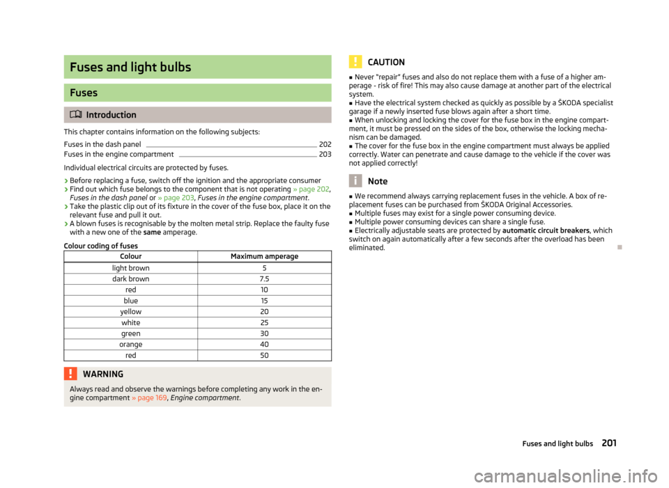
This chapter contains information on the following subjects:
Fuses in the dash panel 202
Fuses in the engine compartment 203
Individual electrical circuits are protected by fuses.
› Before replacing a fuse, switch off the ignition and the appropriate consumer
› Find out which fuse belongs to the component that is not operating
» page 202,
Fuses in the dash panel or » page 203, Fuses in the engine compartment .
› Take the plastic clip out of its fixture in the cover of the fuse box, place it on the
relevant fuse and pull it out.
› A blown fuses is recognisable by the molten metal strip. Replace the faulty fuse
with a new one of the
same amperage.
Colour coding of fuses Colour Maximum amperage
light brown 5
dark brown 7.5
red 10
blue 15
yellow 20
white 25
green 30
orange 40
red 50WARNING
Always read and observe the warnings before completing any work in the en-
gine compartment » page 169, Engine compartment . CAUTION
■ Never “repair” fuses and also do not replace them with a fuse of a higher am-
perage - risk of fire! This may also cause damage at another part of the electrical
system.
■ Have the electrical system checked as quickly as possible by a ŠKODA specialist
garage if a newly inserted fuse blows again after a short time.
■ When unlocking and locking the cover for the fuse box in the engine compart-
ment, it must be pressed on the sides of the box, otherwise the locking mecha-
nism can be damaged. ■ The cover for the fuse box in the engine compartment must always be applied
correctly. Water can penetrate and cause damage to the vehicle if the cover was
not applied correctly! Note
■ We recommend always carrying replacement fuses in the vehicle. A box of re-
placement fuses can be purchased from
ŠKODA Original Accessories.
■ Multiple fuses may exist for a single power consuming device.
■ Multiple power consuming devices can share a single fuse.
■ Electrically adjustable seats are protected by automatic circuit breakers, which
switch on again automatically after a few seconds after the overload has been
eliminated. Ð
201
Fuses and light bulbs
Page 206 of 225
Bulbs
ä
Introduction
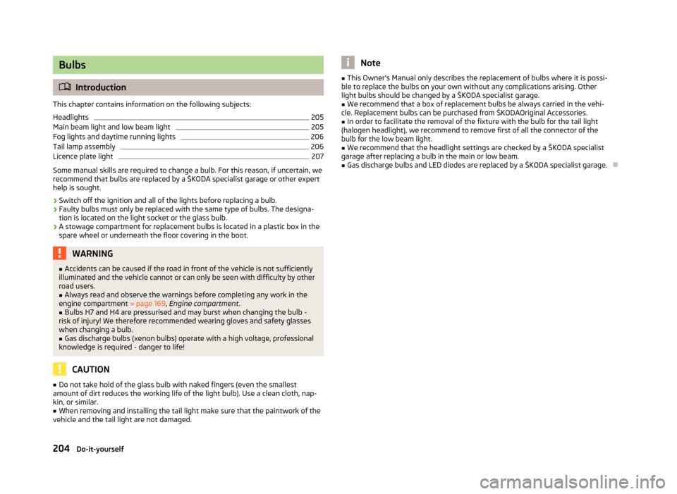
This chapter contains information on the following subjects:
Headlights 205
Main beam light and low beam light 205
Fog lights and daytime running lights 206
Tail lamp assembly 206
Licence plate light 207
Some manual skills are required to change a bulb. For this reason, if uncertain, we
recommend that bulbs are replaced by a ŠKODA specialist garage or other expert
help is sought.
› Switch off the ignition and all of the lights before replacing a bulb.
› Faulty bulbs must only be replaced with the same type of bulbs. The designa-
tion is located on the light socket or the glass bulb.
› A stowage compartment for replacement bulbs is located in a plastic box in the
spare wheel or underneath the floor covering in the boot. WARNING
■ Accidents can be caused if the road in front of the vehicle is not sufficiently
illuminated and the vehicle cannot or can only be seen with difficulty by other
road users.
■ Always read and observe the warnings before completing any work in the
engine compartment »
page 169, Engine compartment .
■ Bulbs H7 and H4 are pressurised and may burst when changing the bulb -
risk of injury! We therefore recommended wearing gloves and safety glasses
when changing a bulb. ■ Gas discharge bulbs (xenon bulbs) operate with a high voltage, professional
knowledge is required - danger to life! CAUTION
■ Do not take hold of the glass bulb with naked fingers (even the smallest
amount of dirt reduces the working life of the light bulb). Use a clean cloth, nap-
kin, or similar. ■ When removing and installing the tail light make sure that the paintwork of the
vehicle and the tail light are not damaged. Note
■ This Owner's Manual only describes the replacement of bulbs where it is possi-
ble to replace the bulbs on your own without any complications arising. Other
light bulbs should be changed by a
ŠKODA specialist garage.
■ We recommend that a box of replacement bulbs be always carried in the vehi-
cle. Replacement bulbs can be purchased from
ŠKODAOriginal Accessories.
■ In order to facilitate the removal of the fixture with the bulb for the tail light
(halogen headlight), we recommend to remove first of all the connector of the
bulb for the low beam light. ■ We recommend that the headlight settings are checked by a ŠKODA specialist
garage after replacing a bulb in the main or low beam. ■ Gas discharge bulbs and LED diodes are replaced by a ŠKODA specialist garage. Ð
204 Do-it-yourself
Page 212 of 225
Specifications and engine oil capacity
The engine has been factory-filled with a high-grade oil that can be use through-
out the year - except in extreme climate zones.
Various oils can be mixed together when refilling. However, this does not apply to
vehicles with flexible service intervals.
Engine oils are, of course, undergoing continuous further development. Thus the
information stated in this Owner's Manual is only correct at the time of publica-
tion.
ŠKODA Service Partners are informed about the latest changes by
ŠKODA. We
therefore recommend that the oil change is completed by a ŠKODA Service Part-
ner.
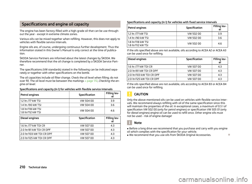
The specifications (VW standards) stated in the following can be indicated sepa-
rately or together with other specifications on the bottle.
The oil capacities include oil filter change. Check the oil level when filling; do not
over fill. The oil level must be between the markings » page 172, Checking the en-
gine oil level .
Specifications and capacity (in l) for vehicles with flexible service intervals
Petrol engines SpecificationFilling lev-
el
1.2 ltr./77 kW TSI VW 504 003.9
1.4 ltr./90 kW TSI VW 504 003.6
1.8 ltr/118 kW TSI
1.8 ltr/112 kW TSI VW 504 00
4.6Diesel engines
Specification Filling lev-
el
1.6 ltr./77 kW TDI CR VW 507 004.3
2.0 ltr/81 kW TDI CR DPF VW 507 004.3
2.0 ltr/103 kW TDI CR DPF VW 507 004.3
2.0 ltr/125 kW TDI CR DPF VW 507 004.3 Specifications and capacity (in l) for vehicles with fixed service intervals
Petrol engines SpecificationFilling lev-
el
1.2 ltr./77 kW TSI VW 502 003.9
1.4 ltr./90 kW TSI VW 502 003.6
1.8 ltr/118 kW TSI
1.8 ltr/112 kW TSI VW 502 00
4.6 If the oils specified above are not available, oils according to ACEA
A2 or ACEA A3
can be used once for refilling.
Diesel engines Specification Filling lev-
el
1.6 ltr./77 kW TDI CR VW 507 004.3
2.0 ltr/81 kW TDI CR DPF VW 507 004.3
2.0 ltr/103 kW TDI CR DPF VW 507 004.3
2.0 ltr/125 kW TDI CR DPF VW 507 004.3 If the oils specified above are not available, oils according to ACEA
B3 or ACEA B4
can be used once for refilling. CAUTION
Only the above-mentioned oils can be used on vehicles with flexible service inter-
vals. We recommend always refilling with oil of the same specification since this
will maintain the properties of the oil. In exceptional cases, a maximum of 0.5
l of
specification VW 502 00 (only for petrol engines) or specification VW 505 01 (only
for diesel engines) engine oil can be used to refill once. Other engine oils must
not be used - risk of engine damage! Note
■ Before a long drive we recommend that you purchase and carry with you engine
oil which complies with the specification for your vehicle. ■ We recommend that you use oils from ŠKODA Original Accessories. Ð210
Technical data
Page 217 of 225
Index
A
Ability to climb see Slope angle 153
ABS Function 97
Warning light 22
Accessories 189
Active driver-steering recommendation (DSR) 96
Adjusting Exterior mirror 53
Adjusting seats 129
Adjustment Seat 56
Aerial 161
see Radio reception 163
Airbag 137
Deployment 137
Front airbag 138
Head airbag 141
Knee airbag 139
Side airbag 140
Airbag system 137
Air conditioning system Air outlet vents 81
Climatronic 86
Manual air conditioning system 83
Alarm 31
Anti-theft alarm system 31
Antilock brake system 97
Armrest 75
Ashtray 70
Assistance systems OFF ROAD 98
Assist systems ABS 22, 97
Cruise control systems (CCS) 104EDL 98
ESC 22, 96
Park assist 101
Parking aid 100
START/STOP 106
TCS 22, 97
Auto Check Control 17
Automatic driving lamp control 40
Automatic gearbox 109
Dynamic shift programme 112
Emergency programme 112
Information for driving 109
Kickdown 112
Manual shifting of gears 111
Parking 110
Selector lever-emergency unlocking 113
Selector lever lock 111
Selector lever positions 110
Starting off 110
Stopping 110
Tiptronic 111
Automatic load deactivation 180
Auxiliary heating (auxiliary heating and ventila- tion) 88
Avoiding damage to your vehicle 150
B
Before setting off 128
Belts 132
Belt tensioners 135
Bonnet Closing 171
Opening 171
Boot Class
N1 vehicles 63
Cover 65
Emergency unlocking 34
Fastening elements 64
Fixing nets 65
Folding hooks 64Light 47
see Boot lid 33
Unlocking the boot lid 34
Variable loading floor 66
Boot lid 33
Automatic locking 33
Warning light 21
Brake assist 96
Brake booster 96
Brake fluid Checking 175
Brakes Brake assist systems 94
Handbrake 96
Indicator light 19
Running in 146
Braking Brake fluid 175
Breakdown kit 194
Bulbs Replacing 204
Button in the driver's door Electric power windows 34
C
Car computer see Multifunction display 12
Car jack 190
Carrier 68
Catalytic converter 146
CD changer 126
Central locking button 29
Central locking system 27
lock 29
unlock 28
Changes 189
Changing Engine oil 173
Wheel 191
215
Index
Page 218 of 225
Charging a vehicle battery 179
Checking Battery electrolyte level 178
Brake fluid 175
Coolant level 174
Engine oil 172
Oil level 172
Windscreen washer fluid 176
Children and safety 143
Child safety Side airbag 144
Child safety lock 27
Child seat Classification 144
ISOFIX 145
on the front passenger seat 143
Suitability 144
TOP TETHER 145
Chrome parts refer to Taking care of your vehicle 162
Cigarette lighter 71
Cleaning 160
Artificial leather 165
Headlight lenses 163
Material coverings 165
Materials 165
Natural leather 165
Plastic parts 162
Wheels 164
Clock 11
Clothes hooks 78
Cockpit 12-volt power socket 71
Ashtray 70
Cigarette lighter 71
General view 7
Light 46
Storage compartments 72
Compartments 72
Computer see Multifunction display 12Coolant
Checking 174
Replenishing 174
Coolant temperature gauge display 9
Correct seated position 129
Counter for distance driven 10
Cruise control system (CCS) 104
Cup holder front 69
rear 70
D
Daytime running lights 40
De-icing the windscreen and rear window 47
Deactivating an airbag 141
Deactivating an airbag 141
Delayed locking of the boot lid see Boot lid 33
Diesel refer to Fuel 169
Diesel fuel Operation in winter 169
Diesel particulate filter 23
Digital clock 11
Dipstick 172
Display Service interval 10
Distance driven 10
Door Child safety lock 27
Indicator light for an open door 20
Doors Emergency locking 32
Driving Abroad 150
Driving through water on the street 151
Emissions 208Fuel consumption 208
Maximum speed 211
Driving off-road after driving off-road 156
Before driving 153
Changing gear when driving off-road 154
Explanation of technical terms 152
Ground clearance 152
Hillside angle 155
OFF ROAD mode 98
Overhang angle 152
Stuck vehicle 155
DVD-preinstallation 127
E
Economical and environmentally friendly driving 147
EDL Operating principle 98
Electrical power windows Button in the driver's door 34
Electric power windows Central locking system 36
Electronic differential lock (EDL) 98
Electronic immobiliser 93
Emergency Automatic gearbox 112
Changing a wheel 191
Hazard warning light system 44
Jump-starting 197
locking of the doors 32
panormaic sliding roof 38
Selector lever-unlocking 113
Towing the vehicle 198
Tyre repair 194
Unlocking the boot lid 34
Emissions 208
Engine Running in 146
Starting and stopping the engine 92
216 Index
Page 219 of 225
Engine compartment
Brake fluid 175
Coolant 173
Overview 171
Vehicle battery 176
Engine oil Capacity 210
Changing 173
Checking 172
Replenishing 172
Specification 210
Engine revolutions counter 9
Environment 147
Environmental compatibility 149
Environmentally friendly driving 147
ESC Function 96
Indicator light 22
F
Fire extinguisher 190
First-aid kit 190
Folding table 76
Footmats 100
Front airbag 138
Front seats 55
Fuel 167
Diesel 169
Fuel gauge 9
gauge 9
refer to Fuel 167
Refuelling 167
Unleaded petrol 168
Fuel consumption 147
Fuses Assignment 201
Replacing 201 G
Gear Recommended gear 11
General view Cockpit 7
Glow plug system Warning light 23
GSM 116, 119
H
Handbrake 96
Head airbag 141
Headlight cleaning system Headlight cleaning system 51
Headlights Driving abroad 150
Head restraint 59
Heating 82
Defrosting windows 82
Exterior mirror 53
Recirculated air mode 83
Seats 58
Windscreen and rear window 47
Horn 7
I
Ignition 94
Ignition lock 94
Immobiliser 93
Indicator lights 18
Information display see MAXI DOT 15
Instrument Cluster 8
See Instrument Cluster 8
Instrument lighting 43
Interior monitor 32
Internet connection 122ISOFIX 145
J
Jacking points Raise vehicle 193
Jump-starting 197
K
Knee airbag 139
L
Lever Main beam 45
Turn signal 45
Levers Windscreen wipers 49
Light Automatic driving lamp control 40
Cockpit 46
COMING HOME/LEAVING HOME function 41
Daytime running lights 40
Fog lights 42
Fog lights with the function CORNER 42
Hazard warning light system 44
Headlight beam adjustment 44
Headlight flasher 45
Low beam 40
Main beam 45
Parking light 40, 41
Rear fog light 43
Replacing bulbs 204
Tourist light 42
Turn signal 45
Lights Cornering lights 41
Indicator lights 18
switching lights on and off 40
Loads 208
217
Index