engine SKODA YETI 2013 1.G / 5L User Guide
[x] Cancel search | Manufacturer: SKODA, Model Year: 2013, Model line: YETI, Model: SKODA YETI 2013 1.G / 5LPages: 266, PDF Size: 26.71 MB
Page 22 of 266
Traction control (ASR) switched offFirst read and observe the introductory information and safety warn-ings
on page 14.
The warning light lights up when the ASR is turned off by pressing the Symbol
key
» page 137 , Traction Control System (TCS) or » page 136 , Electronic Sta-
bility Control (ESC) .
The following message is shown in the MAXI DOT display. Traction control (ASR) is deactivated.
Antilock brake system (ABS)
First read and observe the introductory information and safety warn-
ings
on page 14.
If the indicator light
lights up, there is a fault in the ABS.
The following message is shown in the MAXI DOT display. Error: ABS
The vehicle will only be braked by the normal brake system without the ABS.
Seek assistance from a specialist garage immediately.
Further information » page 137, Antilock brake system (ABS) .
WARNING■
If you have to stop for technical reasons, then park the vehicle at a safe dis-
tance from the traffic, switch off the engine and activate the hazard warning
light system » page 52. The warning triangle must be set up at the prescri-
bed distance - observe the national legal provisions when doing so.■
If the warning light » page 15 is displayed together with warning light ,
do not continue your journey! Seek help from a specialist garage.
■
A fault to the ABS system or the braking system can increase the vehicle's
braking distance – risk of accident!
Rear fog light
First read and observe the introductory information and safety warn-
ings
on page 14.
The warning light comes on when the rear fog light is switched on.
Further information » page 51.
Bulb failure
First read and observe the introductory information and safety warn-ings
on page 14.
The indicator light
lights up if a bulb is faulty.
The indicator light
lights up within a few seconds after switching on the igni-
tion or when a light with a faulty bulb is switched on.
The following message, for example, may be shown in the MAXI DOT display.
INFORMATION Check front right low beam!
Exhaust inspection system
First read and observe the introductory information and safety warn-
ings
on page 14.
If the indicator light
lights up, there is a fault in the exhaust inspection system.
The system allows the vehicle to run in emergency mode.
Seek assistance from a specialist garage immediately.
Glow plug system (diesel engine)
First read and observe the introductory information and safety warn-ings
on page 14.
The warning light
lights up after the ignition has been switched on. Once the
light has gone out, the engine can be started immediately.
There is a fault in the glow plug system if the indicator light
does not come on
at all or lights up continuously .
19Instruments and Indicator Lights
Page 23 of 266
If the indicator light begins to flash while driving, a fault exists in the engine
control. The system allows the vehicle to run in emergency mode.
Seek assistance from a specialist garage immediately.
Engine performance check (petrol engine)
First read and observe the introductory information and safety warn-ings
on page 14.
If the indicator light lights up, there is a fault in the engine control. The system
allows the vehicle to run in emergency mode.
Seek assistance from a specialist garage immediately.
Diesel particulate filter (diesel engine)
First read and observe the introductory information and safety warn-ings
on page 14.
The diesel particulate filter separates the soot particles from the exhaust. The
soot particles collect in the diesel particulate filter where they are burnt on a reg-
ular basis.
If the indicator light
lights up , soot has accumulated in the filter.
To clean the filter, and where traffic conditions permit »
, drive as follows for at
least 15 minutes or until the indicator light
goes out.
4 or 5 Gear engaged (automatic transmission: position S).
Vehicle speed at least 70 km/h.
Engine speed between 1800-2500 rpm.
If the filter is properly cleaned, the warning icon
goes out .
If the filter is not properly cleaned, the warning light
does not go out and the
warning light
begins to flash.
The following message is shown in the MAXI DOT display. Diesel particle filter: Owner's manual!
The system allows the vehicle to run in emergency mode. After switching the ig- nition off and on again the indicator light, the indicator light
also lights up .
Seek assistance from a specialist garage immediately.
WARNING■ The diesel particle filter achieves very high temperatures. Therefore do not
park in areas where the hot filter can come into direct contact with dry grass
or other combustible materials – there is the risk of fire!■
Always adjust your speed to suit weather, road, region and traffic condi-
tions. The recommendations indicated by the indicator light must not tempt
you to disregard the national regulations for road traffic.
CAUTION
■ As long as the indicator light lights up, one must take into account an in-
creased fuel consumption and in certain circumstances a power reduction of the
engine.■
Using diesel fuel with an increased sulphur content can considerably reduce the
life of the diesel particle filter. A ŠKODA partner will be able to tell you which
countries use diesel fuel with a high sulphur content.
Note
■ To assist the combustion process of the soot particles in the filter, we recom-
mend that regularly driving short distances be avoided.■
If the engine is turned off during the filter cleaning process or shortly after-
wards, the cooling fan may turn on automatically for a few minutes.
Fuel reserve
First read and observe the introductory information and safety warn-ings
on page 14.
The indicator light will come on if the fuel level is less than 10.5 litres.
An audible signal sounds as a warning signal. The following message is shown in the MAXI DOT display.
Please refuel. Range: ... km
Note
The text in the display goes out only after refuelling and driving a short distance.
20Using the system
Page 26 of 266

Information system
Driver information system
Introduction
This chapter contains information on the following subjects:
Using the information system
23
Ice warning
24
Gear recommendation
24
Door, boot or engine compartment warning
25
Compass point display
25
The information system provides the driver with alerts and messages about in-
dividual vehicle systems. This information and advice is shown in the instrument
cluster display or indicated by the illumination of the corresponding indicator light in the instrument cluster.
Depending on the vehicle equipment, the information system provides the fol-
lowing advice and information.
› Ice warning
» page 24.
› Recommended gear
» page 24.
› Door, boot lid or bonnet warning
» page 25.
› Compass display
» page 25.
› Data relating to the multi-function display (MFD)
» page 25.
› Warning against excessive speeds
» page 27.
› Data relating to the Maxi DOT display
» page 28.
› Service interval display
» page 30.
› Auto Check Control
» page 13.
› Selector lever positions for an automatic gearbox
» page 127.
WARNINGConcentrate fully at all times on your driving! As the driver you are fully re-
sponsible for the operation of your vehicle.
Using the information systemFig. 7
Buttons/dial: on the operating lever / on the multifunction steering
wheel
First read and observe the introductory information and safety warn-ings
on page 23.
Some functions of the information system can be operated using the buttons on
the multifunction steering wheel » Fig. 7 .
Description of the operation
Button/ di-al
» Fig. 7
ActionOperation
ABriefly push up or downSelect dataBriefly push up or downSet data valuesPress and hold buttonOpen main menu in the
MAXI DOT display » page 28BPress brieflyShow dataPress brieflyConfirm dataCPress brieflyto go back one level in the menu of the
MAXI DOT display » page 28Press and hold buttonOpen main menu in the
MAXI DOT display » page 28 23Information system
Page 28 of 266
WARNINGThe driver is always responsible for selecting the correct gear in different driv-
ing situations, such as overtaking.
For the sake of the environment
Correct shifting up has the following advantages.■It helps to reduce fuel consumption.■
It reduces the operating noise.
■
It protects the environment.
■
It benefits the durability and reliability of the engine.
Door, boot or engine compartment warning
First read and observe the introductory information and safety warn-ings
on page 23.
Vehicles with a MAXI DOT display
If at least one door, the boot or bonnet is open, the display indicates the relevant
open door, boot or bonnet vehicle icon.
Vehicles with a segment display
If at least one door or the tailgate is open, the
warning light in the instrument
cluster lights up » page 16.
If at least one door or the tailgate is open, the
warning light in the instrument
cluster lights up » page 17.
An acoustic signal will also sound if you drive the vehicle above 6 km/h when a
door is open.
Compass point display
First read and observe the introductory information and safety warn-
ings
on page 23.
For vehicles with a factory fitted navigation system, an abbreviation for each
point of the compass (depending on the current direction of travel) is shown on
the top left-hand corner of the 1)
display.
The compass point display only operates when the ignition is switched on.
Multifunction display (MFD)
Introduction
This chapter contains information on the following subjects:
Memory
26
Information overview
26
Warning at excessive speeds
28
The driving data is displayed on the multifunction display. The multifunction display only operates if the ignition is switched on. After the ig-nition is switched on, the function that was last selected before switching off the
ignition is displayed.
For vehicles with a MAXI DOT display, the menu item MFD must be selected and
confirmed in the main menu » page 28, MAXI DOT display .
On vehicles with a MAXI DOT display, there is an option to fade out some of the information » page 29, Settings .
WARNING■
Concentrate fully at all times on your driving! As the driver you are fully re-
sponsible for the operation of your vehicle.■
Even at temperatures around +4 °C, black ice may still be on the road sur-
face! Do not only rely upon the information given on the outside temperature
display that there is no ice on the road.
1)
Applies to vehicles using the MAXI DOT display.
25Information system
Page 30 of 266
Driving time
The time travelled since the memory was last erased is displayed.
If you want to measure the time travelled from a particular moment in time on, at
this moment, reset the memory by setting the button to zero » page 26, Memory .
The maximum time indicated in both memories is 19 hours and 59 minutes and on vehicles which are fitted with a MAXI DOT display, it is 99 hours and 59 minutes.
The indicator is set back to zero if this period is exceeded.
Current fuel consumption
The current fuel consumption level is displayed in litres/100 km 1)
. You can use this
information to adapt your driving style to the desired fuel consumption.
The display appears in litres/hour if the vehicle is stationary or driving at a low
speed 2)
.
Average fuel consumption
The average fuel consumption since the memory was last erased is displayed in
litres/100 km 1)
.
If you wish to determine the average fuel consumption over a certain period of
time, you must set the memory at the start of the new measurement to zero » page 26 , Memory . After erasing the memory, no value is displayed until you
have driven approx. 300 m.
The display is updated regularly while you are driving.
Range
The range indicates the distance you can still drive with your vehicle based on the level of fuel in the tank and the same style of driving as before.
The display is shown in steps of 10 km. After lighting up of the indicator light
the display is shown in steps of 5 km.
The fuel consumption over the last 50 km is used to calculate the information.The range will increase if you drive in a more economical manner.
If the memory is set to zero (after disconnecting the battery), a fuel consumptionof 10 l./100 km is calculated for the range; afterwards the value is updated ac-
cording to the style of driving.
Distance travelled
The distance travelled since the memory was last erased is displayed.If you want to measure the distance travelled from a particular moment in time
on, at this moment, reset the memory by setting the button to zero » page 26,
Memory .
The maximum distance indicated in both memories is 1 999 km or 9 999 km on
vehicles with a MAXI DOT display. The indicator is set back to zero if this period is exceeded.
Average speed
The average speed since the memory was last erased is displayed in km/hour .
To determine the average speed over a certain period of time, set the memory tozero at the start of the measurement » page 26, Memory .
After erasing the memory, no data will appear for the first 300 m driven.
The display is updated regularly while you are driving.
Current driving speed
The current speed displayed is identical to the display on the speedometer2
» Fig. 2 on page 10 .
Oil temperature
If the engine oil temperature is in the range 80-110 °C, the engine operating tem-
perature is reached.
If the oil temperature is lower than 80 °C or above 110 °C, avoid high engine revs,
full throttle and high engine loads.
If the oil temperature is lower than 50 °C or if a fault in the system for checking
the oil temperature is present,
.
symbols are displayed instead of the oil tem-
perature.
Warning against excessive speeds
Set the speed limit, for example, for the maximum permissible speed in
town » page 28 , Warning at excessive speeds .
1)
On some models in certain countries, the display appears in kilometres/litre.
2)
On some models in certain countries, – -.- km/ltr. is displayed when the vehicle is stationary.
27Information system
Page 36 of 266
Vehicle keyFig. 11
Key types
First read and observe the introductory information and safety warn- ings
on page 32.
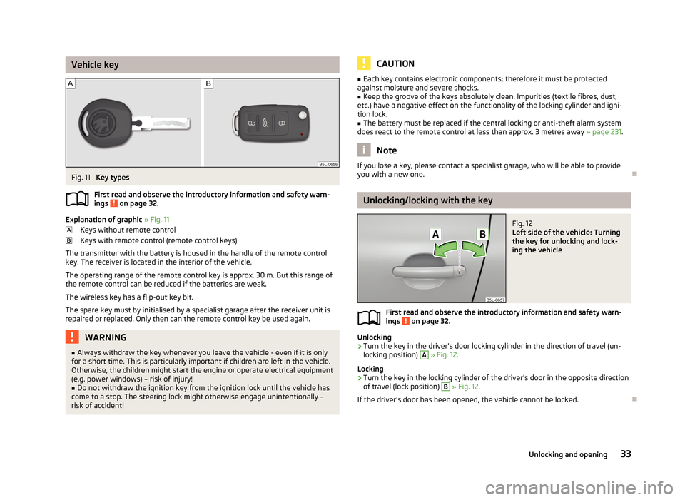
Explanation of graphic » Fig. 11
Keys without remote control
Keys with remote control (remote control keys)
The transmitter with the battery is housed in the handle of the remote control key. The receiver is located in the interior of the vehicle.
The operating range of the remote control key is approx. 30 m. But this range ofthe remote control can be reduced if the batteries are weak.
The wireless key has a flip-out key bit.The spare key must by initialised by a specialist garage after the receiver unit is
repaired or replaced. Only then can the remote control key be used again.
WARNING■ Always withdraw the key whenever you leave the vehicle - even if it is only
for a short time. This is particularly important if children are left in the vehicle.
Otherwise, the children might start the engine or operate electrical equipment
(e.g. power windows) – risk of injury!■
Do not withdraw the ignition key from the ignition lock until the vehicle has
come to a stop. The steering lock might otherwise engage unintentionally – risk of accident!
CAUTION■ Each key contains electronic components; therefore it must be protected
against moisture and severe shocks.■
Keep the groove of the keys absolutely clean. Impurities (textile fibres, dust,
etc.) have a negative effect on the functionality of the locking cylinder and igni-
tion lock.
■
The battery must be replaced if the central locking or anti-theft alarm system
does react to the remote control at less than approx. 3 metres away » page 231.
Note
If you lose a key, please contact a specialist garage, who will be able to provide
you with a new one.
Unlocking/locking with the key
Fig. 12
Left side of the vehicle: Turning
the key for unlocking and lock-
ing the vehicle
First read and observe the introductory information and safety warn-
ings on page 32.
Unlocking
›
Turn the key in the driver's door locking cylinder in the direction of travel (un- locking position)
A
» Fig. 12 .
Locking
›
Turn the key in the locking cylinder of the driver's door in the opposite direction
of travel (lock position)
B
» Fig. 12 .
If the driver's door has been opened, the vehicle cannot be locked.
33Unlocking and opening
Page 54 of 266
Fog lightsFig. 28
Light switch: Switch on the front
fog lamp
First read and observe the introductory information and safety warn-
ings on page 47.
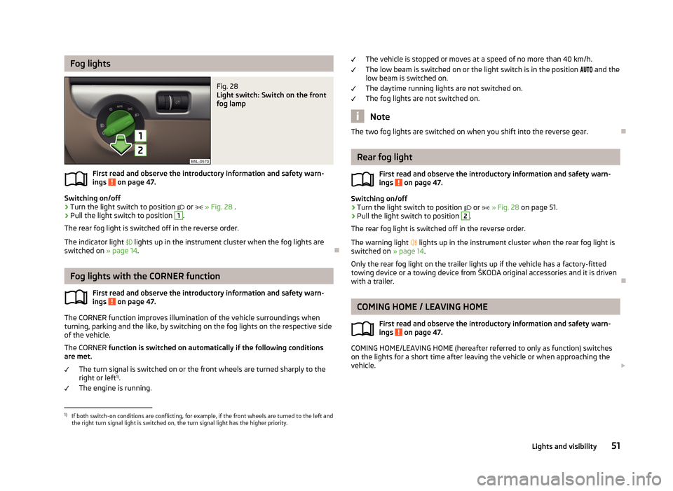
Switching on/off
›
Turn the light switch to position
or
» Fig. 28 .
›
Pull the light switch to position
1
.
The rear fog light is switched off in the reverse order.
The indicator light
lights up in the instrument cluster when the fog lights are
switched on » page 14.
Fog lights with the CORNER function
First read and observe the introductory information and safety warn-ings
on page 47.
The CORNER function improves illumination of the vehicle surroundings when
turning, parking and the like, by switching on the fog lights on the respective side
of the vehicle.
The CORNER function is switched on automatically if the following conditions
are met.
The turn signal is switched on or the front wheels are turned sharply to the
right or left 1)
.
The engine is running.
The vehicle is stopped or moves at a speed of no more than 40 km/h.
The low beam is switched on or the light switch is in the position and the
low beam is switched on.
The daytime running lights are not switched on. The fog lights are not switched on.
Note
The two fog lights are switched on when you shift into the reverse gear.
Rear fog light
First read and observe the introductory information and safety warn-
ings
on page 47.
Switching on/off
›
Turn the light switch to position
or
» Fig. 28 on page 51.
›
Pull the light switch to position
2
.
The rear fog light is switched off in the reverse order.
The warning light
lights up in the instrument cluster when the rear fog light is
switched on » page 14.
Only the rear fog light on the trailer lights up if the vehicle has a factory-fitted
towing device or a towing device from ŠKODA original accessories and it is driven
with a trailer.
COMING HOME / LEAVING HOME
First read and observe the introductory information and safety warn-ings
on page 47.
COMING HOME/LEAVING HOME (hereafter referred to only as function) switches on the lights for a short time after leaving the vehicle or when approaching the
vehicle.
1)
If both switch-on conditions are conflicting, for example, if the front wheels are turned to the left and
the right turn signal light is switched on, the turn signal light has the higher priority.
51Lights and visibility
Page 58 of 266
Visibility
Introduction
This chapter contains information on the following subjects:
Windscreen and rear window heater
55
Sun visors
55
Windscreen and rear window heater
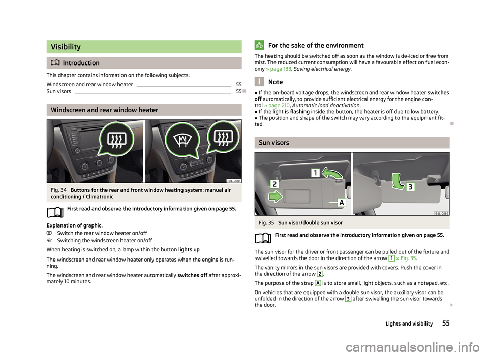
Fig. 34
Buttons for the rear and front window heating system: manual air
conditioning / Climatronic
First read and observe the introductory information given on page 55.
Explanation of graphic.Switch the rear window heater on/off
Switching the windscreen heater on/off
When heating is switched on, a lamp within the button lights up
The windscreen and rear window heater only operates when the engine is run-
ning.
The windscreen and rear window heater automatically switches off after approxi-
mately 10 minutes.
For the sake of the environmentThe heating should be switched off as soon as the window is de-iced or free from
mist. The reduced current consumption will have a favourable effect on fuel econ-
omy » page 133 , Saving electrical energy .
Note
■
If the on-board voltage drops, the windscreen and rear window heater switches
off automatically, to provide sufficient electrical energy for the engine con-
trol » page 210 , Automatic load deactivation .■
If the light is flashing inside the button, the heater is off due to low battery.
■
The position and shape of the switch may vary according to the equipment fit-
ted.
Sun visors
Fig. 35
Sun visor/double sun visor
First read and observe the introductory information given on page 55.
The sun visor for the driver or front passenger can be pulled out of the fixture and
swivelled towards the door in the direction of the arrow
1
» Fig. 35 .
The vanity mirrors in the sun visors are provided with covers. Push the cover in
the direction of the arrow
2
.
The purpose of the strap
A
is to store small, light objects, such as a notepad, etc.
On vehicles that are equipped with a double sun visor, the auxiliary visor can be
unfolded in the direction of the arrow
3
after swivelling the sun visor towards
the door.
55Lights and visibility
Page 61 of 266
Alternative park position of the rear window wiperFirst read and observe the introductory information and safety warn-ings
on page 56.
Each time after switching off the engine for the second time, the wiper blade ofthe rear window wiper is tilted. This prolongs the life of the wiper blade.
Activation/deactivation
›
Switch on the ignition.
›
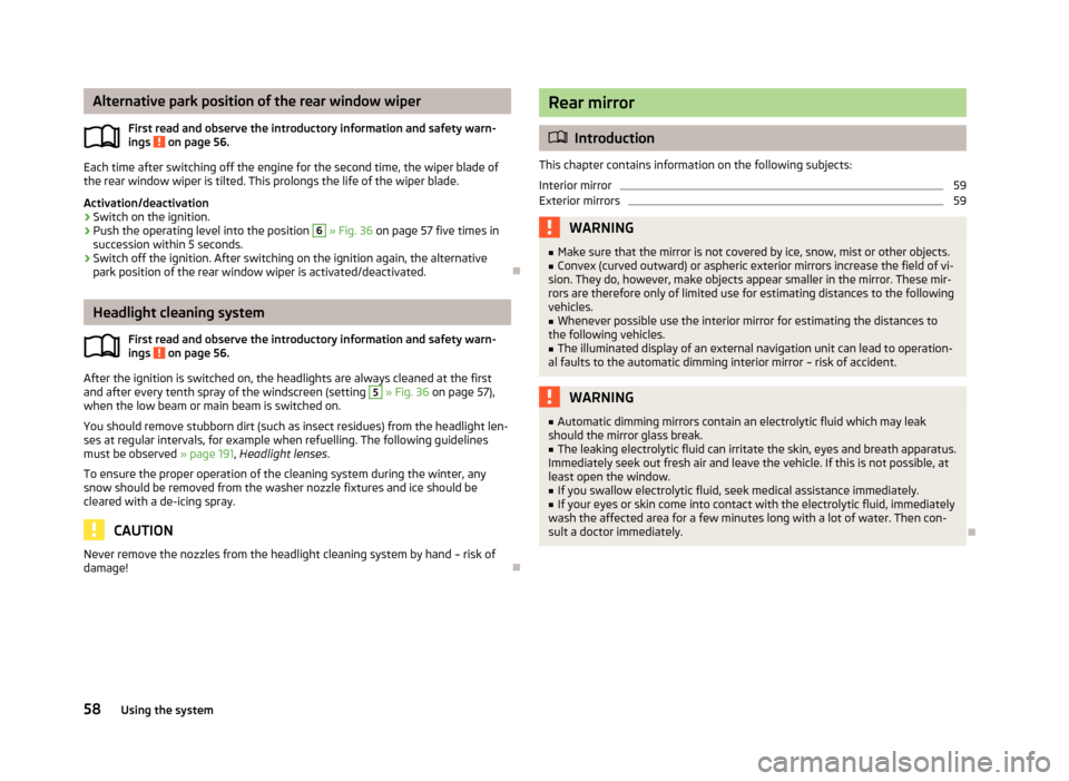
Push the operating level into the position
6
» Fig. 36 on page 57 five times in
succession within 5 seconds.
›
Switch off the ignition. After switching on the ignition again, the alternative
park position of the rear window wiper is activated/deactivated.
Headlight cleaning system
First read and observe the introductory information and safety warn-
ings
on page 56.
After the ignition is switched on, the headlights are always cleaned at the first
and after every tenth spray of the windscreen (setting
5
» Fig. 36 on page 57),
when the low beam or main beam is switched on.
You should remove stubborn dirt (such as insect residues) from the headlight len-
ses at regular intervals, for example when refuelling. The following guidelines
must be observed » page 191, Headlight lenses .
To ensure the proper operation of the cleaning system during the winter, any
snow should be removed from the washer nozzle fixtures and ice should be
cleared with a de-icing spray.
CAUTION
Never remove the nozzles from the headlight cleaning system by hand – risk of
damage!
Rear mirror
Introduction
This chapter contains information on the following subjects:
Interior mirror
59
Exterior mirrors
59WARNING■ Make sure that the mirror is not covered by ice, snow, mist or other objects.■Convex (curved outward) or aspheric exterior mirrors increase the field of vi-
sion. They do, however, make objects appear smaller in the mirror. These mir-
rors are therefore only of limited use for estimating distances to the following
vehicles.■
Whenever possible use the interior mirror for estimating the distances to
the following vehicles.
■
The illuminated display of an external navigation unit can lead to operation-
al faults to the automatic dimming interior mirror – risk of accident.
WARNING■ Automatic dimming mirrors contain an electrolytic fluid which may leak
should the mirror glass break.■
The leaking electrolytic fluid can irritate the skin, eyes and breath apparatus.
Immediately seek out fresh air and leave the vehicle. If this is not possible, at
least open the window.
■
If you swallow electrolytic fluid, seek medical assistance immediately.
■
If your eyes or skin come into contact with the electrolytic fluid, immediately
wash the affected area for a few minutes long with a lot of water. Then con- sult a doctor immediately.
58Using the system
Page 63 of 266
Folding-in both of the exterior mirrors using the remote control keyThe entire mirror can be folded by pressing the symbol button on the remote
control key for 2 seconds. All windows must be closed.
The exterior mirror is folded back into the driving position when the ignition isswitched on.
Automatic dimming mirror
The exterior mirrors are dimmed together with the automatic dimming interior
mirror » page 59 .
Fold in passenger's mirror
On vehicles fitted with the memory function for the driver's seat » page 63, the
mirror tilts down slightly when the reverse gear is engaged and the rotary knob is
in the position
or in position
on vehicles with right-hand drive » Fig. 38 . This
provides an aid in seeing the kerb of the pavement when parking the car.
The mirror returns into its initial position after the rotary knob is moved out of po-
sition
(or position
on vehicles with right-hand drive) and put into another posi-
tion or if the speed is more than 15 km/h.
This mode can be enabled or disabled via the Maxi DOT display in the Travel
mode » page 29 menu option.
Memory function for mirrors
On vehicles fitted with a memory function for the driver seat, the relevant setting for the exterior mirrors can also be stored automatically when the seat position is
stored » page 63 .WARNINGDo not touch the exterior mirror surfaces, if the exterior mirror heating is
switched on - hazard of burning.
CAUTION
Never mechanically fold in or fold back the exterior mirrors with the fold-in func-
tion by hand as this will damage the electric drive.
Note
■
The mirror heater only operates when the engine is running and up to an out-
side temperature of +35 ℃.■
If the power setting function fails at any time, the exterior mirrors can be set by
hand by pressing on the edge of the mirror surface.
60Using the system