instrument cluster SKODA YETI 2013 1.G / 5L User Guide
[x] Cancel search | Manufacturer: SKODA, Model Year: 2013, Model line: YETI, Model: SKODA YETI 2013 1.G / 5LPages: 266, PDF Size: 26.71 MB
Page 41 of 266
WARNING■Make sure that the door has closed correctly as it can open suddenly while
driving – risk of death!■
Only open and close the door when there is no one in the opening/closing
range – risk of injury!
■
An opened door can close automatically if there is a strong wind or the vehi-
cle is on an incline – risk of injury!
■
Never drive with the doors open - it can be fatal!
KESSY
Introduction
This chapter contains information on the following subjects:
Information messages
38
Parking vehicle
38
The KESSY system (Keyless Entry Start Exit System) enables unlocking and lock-
ing of the vehicle without actively using the remote control key.
Information messages
First read and observe the introductory information given on page 38.
Key in the vehicle
The protection against inadvertently locking the key in the vehicle unlocks the vehicle automatically if the following conditions are met.
The vehicle, including the boot lit, has been locked.The key with which the vehicle has been locked remains in the vehicle in the
zone
D
» Fig. 14 on page 35.
The turn signal lights flash four times as confirmation that the vehicle has been
unlocked again.
The following message is shown in the information cluster display. Key in vehicle.
KEY IN VEHICLE
Additionally, on vehicles which are fitted with the anti-theft alarm system, an au-
dible signal sounds.
The system has not found a key
If the system has not found a key in the vehicle, the following message appears in the display of the instrument cluster.
Key not found.
NO KEY
This can occur if the key is outside the vehicle, the battery in the key is dis-
charged, the key is defective or the electromagnetic field is strongly disturbed.
Fault in KESSY system
If there is a fault in the KESSY system, the following message will appear in the display of the instrument cluster.
Keyless faulty.
CHECK KEYLESS
Low voltage of the key battery
If the voltage of the battery in the remote control key is too low, the following
message appears in the display of the instrument cluster.
Renew key battery!
KEY BATTERY
Change the key battery » page 231.
Parking vehicle
First read and observe the introductory information given on page 38.
If the vehicle is not unlocked within 60 or 90 hours, the sensors in the handle of
the driver or front passenger's door are deactivated automatically » Fig. 14 on
page 35.
Activation after 60 hours
›
Unlock the driver's door using the sensor
2
» Fig. 14 on page 35.
›
Press the handle of the boot lid.
›
Unlock the vehicle using the symbol button
on the remote control key.
›
Unlocking the driver's door in an emergency » page 232.
38Using the system
Page 52 of 266
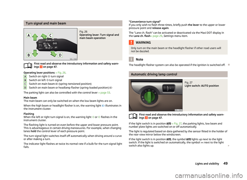
Turn signal and main beamFig. 26
Operating lever: Turn signal and
main beam operation
First read and observe the introductory information and safety warn-
ings on page 47.
Operating lever positions » Fig. 26 .
Switch on right
turn signal
Switch on left
turn signal
Switch on main beam
(spring-tensioned position)
Switch on main beam or headlamp flasher (spring-loaded position)
The parking light can also be controlled with the control lever » page 53.
Main beam
The main beam can only be switched on when the low beam lights are on.
When the high beam or headlight flasher is on, the warning light
illuminates in
the instrument cluster.
Flashing
When the left or right turn signal is on, the warning light
or
flashes in the
instrument cluster.
The flashing light is turned on even before the upper and lower pressure point.
This is advantageous in certain driving manoeuvres. For example, when changing
lanes hold the control lever of each pressure point.
The turn signal light switches itself off automatically when driving around a curve
or after making a turn.
The indicator light flashes at twice its normal rate if a bulb for the turn signal light fails.
ABCD“Convenience turn signal”
If you only wish to flash three times, briefly push the lever to the upper or lower
pressure point and release again.
The “Lane ch. flash” can be activated or deactivated via the Maxi DOT display in
the Lane ch. flash » page 29, Settings menu item.WARNINGOnly turn on the main beam or the headlight flasher if other road users will
not be dazzled.
Note
The headlight flasher system can also be operated if the ignition is switched off.
Automatic driving lamp control
Fig. 27
Light switch: AUTO position
First read and observe the introductory information and safety warn- ings on page 47.
If the light switch is in position
» Fig. 27 , the parking lights, low beam and
number plate lights are switched on or off automatically.
The light is regulated based on data gathered by the sensor fitted in the holder of
the rear-view mirror below the windscreen.
If the light switch is in position
, the symbol
lights up next to the light
switch. If the light is switched on automatically, the symbol
next to the light
switch also lights up.
49Lights and visibility
Page 54 of 266
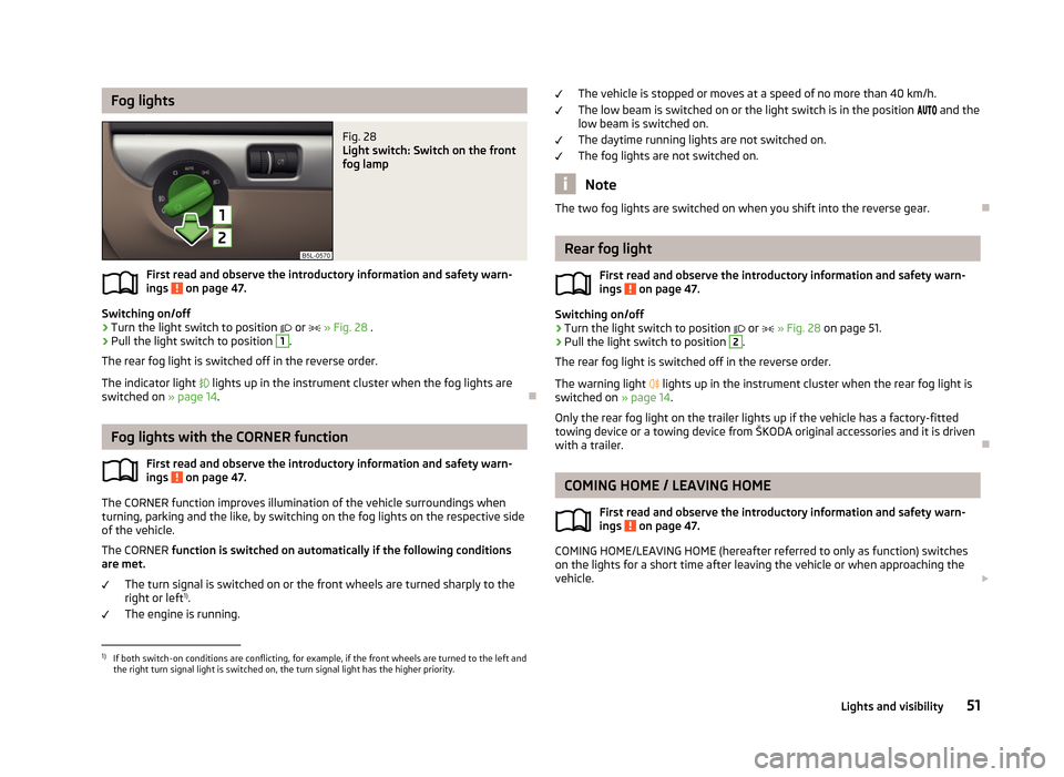
Fog lightsFig. 28
Light switch: Switch on the front
fog lamp
First read and observe the introductory information and safety warn-
ings on page 47.
Switching on/off
›
Turn the light switch to position
or
» Fig. 28 .
›
Pull the light switch to position
1
.
The rear fog light is switched off in the reverse order.
The indicator light
lights up in the instrument cluster when the fog lights are
switched on » page 14.
Fog lights with the CORNER function
First read and observe the introductory information and safety warn-ings
on page 47.
The CORNER function improves illumination of the vehicle surroundings when
turning, parking and the like, by switching on the fog lights on the respective side
of the vehicle.
The CORNER function is switched on automatically if the following conditions
are met.
The turn signal is switched on or the front wheels are turned sharply to the
right or left 1)
.
The engine is running.
The vehicle is stopped or moves at a speed of no more than 40 km/h.
The low beam is switched on or the light switch is in the position and the
low beam is switched on.
The daytime running lights are not switched on. The fog lights are not switched on.
Note
The two fog lights are switched on when you shift into the reverse gear.
Rear fog light
First read and observe the introductory information and safety warn-
ings
on page 47.
Switching on/off
›
Turn the light switch to position
or
» Fig. 28 on page 51.
›
Pull the light switch to position
2
.
The rear fog light is switched off in the reverse order.
The warning light
lights up in the instrument cluster when the rear fog light is
switched on » page 14.
Only the rear fog light on the trailer lights up if the vehicle has a factory-fitted
towing device or a towing device from ŠKODA original accessories and it is driven
with a trailer.
COMING HOME / LEAVING HOME
First read and observe the introductory information and safety warn-ings
on page 47.
COMING HOME/LEAVING HOME (hereafter referred to only as function) switches on the lights for a short time after leaving the vehicle or when approaching the
vehicle.
1)
If both switch-on conditions are conflicting, for example, if the front wheels are turned to the left and
the right turn signal light is switched on, the turn signal light has the higher priority.
51Lights and visibility
Page 100 of 266
Operational problemsFirst read and observe the introductory information and safety warn-
ings
on page 91.
If the cooling system does not operate at outside temperatures higher than +5 °C,
there is a problem in the system. The reasons for this may be.
› One of the fuses has blown. Check the fuse and replace if necessa-
ry » page 236 .
› The cooling system has switched off automatically for a short time because the
coolant temperature of the engine is too hot » page 11.
If you are not able to resolve the operational problem yourself, or if the cooler output has reduced, switch off the cooling system and seek assistance from a
specialist garage.
Auxiliary heating (auxiliary heating and ventilation)
Introduction
This chapter contains information on the following subjects:
Switching on and off directly
98
System settings
98
Radio remote control
99
Conditions for the functioning of auxiliary heating (Aux. heating and ventilation),
hereinafter referred to only as auxiliary heating (Aux. heating).
The charge state of the vehicle battery is sufficient.
The fuel supply is adequate (the warning icon
is not lit in the display of the
instrument cluster).
Auxiliary ventilation
The auxiliary ventilation enables fresh air to flow into the vehicle interior by
switching off the engine, whereby the interior temperature is effectively de-
creased (e.g. with the vehicle parked in the sun).
Auxiliary heating (auxiliary heating)
The auxiliary heating (auxiliary heating) can be used when stationary, when the engine is switched off to preheat the vehicle and also while driving (e.g. during
the heating phase of the engine).
The auxiliary heater (parking heater) functions in connection with the air-condi-
tioning system or Climatronic.
The auxiliary heating (auxiliary heating) also warms up the engine.
The auxiliary heating (parking heating) warms up the coolant by combusting fuel
from the vehicle tank.
The coolant warms up the air, which (if the blower speed is not set to zero) flows into the passenger compartment.WARNING■ The auxiliary heater (independent vehicle heater) must never be operated in
closed rooms (e.g. garages) – risk of poisoning!■
The auxiliary heating (parking heating) must not be allowed to run during re-
fuelling – risk of fire.
■
The exhaust pipe of the auxiliary heating is located underneath the vehicle.
Therefore, if you wish to operate the auxiliary heating (auxiliary heating), do
not park the vehicle in such a way that the exhaust gases can come into con-
tact with highly flammable materials (e.g. dry grass) or easily inflammable sub-
stances (e.g. spilt fuel) – risk of fire.
CAUTION
■ The running auxiliary heating (auxiliary heating) consumes fuel from the vehicle
tank and automatically controls the filling level. If only a low quantity of fuel is
present in the fuel tank, the auxiliary heater switches itself off.■
The exhaust pipe of the auxiliary heating, which is located on the underside of
the vehicle, must not be clogged and the exhaust flow must not be blocked.
■
If the auxiliary heating is running, the vehicle battery discharges. If the auxiliary
heating and ventilation has been operated several times over a longer period, the
vehicle must be driven a few kilometres in order to recharge the vehicle battery.
Note
■ The auxiliary heating only switches the blower on, if it has achieved a coolant
temperature of approx. 50 °C.■
At low outside temperatures, this can result in a formation of water vapour in
the area of the engine compartment. This is quite normal and is not an operating problem.
97Heating and air-conditioning
Page 113 of 266
If menu item Open is set in the Phone - Wi-Fi - Settings - Encryption menu, the
connection is made automatically.
Connecting using WPS (service for easy connection)›
Switch on the Wi-Fi network » page 109, Switching Wi-Fi network on/off .
›
Open the Phone - Wi-Fi - WPS config. menu in the instrument cluster.
›
In the device to be connected, select the connection using WPS function - see
operating instructions for the device to be connected.
If the Pushbutton menu item is selected in the instrument cluster, the Wi-Fi con-
nection is made automatically.
If the WPS PIN menu item is selected in the instrument cluster, then a PIN must
be entered in the device to be connected and the instrument cluster.
Use WLAN network in MAXI DOT display
First read and observe the introductory information given on page 109.
When a Wi-Fi network is switched on, the following menu items are displayed
when the Wi-Fi menu item is selected:
■ Off - Switch off the WLAN network (depending on the context)
■ Device list - Display a list of external devices
■ Active device - Display a list of active devices
■ Block - Block device connections
■ Known devices - Display a list of known devices
■ Rename - Rename the device
■ Block - Block device connections
■ Device blocked - Display of a list of blocked devices
■ Unblock - Remove the connection block
■ Delete lists - Delete device lists
■ Known devices - Delete the list of known devices
■ Device blocked - Delete the list of blocked devices
■ Both lists - Delete both device lists
■ Password - Use of password to log on to the WLAN network
■ Show - Display a password to log on to the WLAN network
■ Generate - Generate a new password to log on to the WLAN network
■ Wi-Fi Name - Use of WLAN network name
■ Show - Display the WLAN network name
■ Rename - Rename the WLAN network
■
WPS config. - Wi-Fi network connection using WPS
■ Pushbutton - Automatic connection
■ WPS PIN - PIN entry for the connection
■ Data counter - Display information about the volume of data transferred
■ Current conn. - Display of the volume of data transferred for the current con-
nection
■ Total - Display of the total volume of data transferred
■ Reset - Resetting of the information about the volume of data transferred
■ Settings - WLAN network settings
■ Access point - Access point settings
■ Settings - Access point management
■ APN - Change the access point name
■ User name - User Name
■ Password - Password
■ Reset - Reset access point factory settings
■ Prioritisation - Set the connection priority
■ Calls - Set the connection priority for calls
■ Data - Set the connection priority for data transfer
■ Encryption - Set the encryption
■ WPA2 - Enable WPA 2 encryption
■ Open - No encryption
■ Visibility - Set the WLAN network visibility
■ Visible - WLAN network is visible to other devices
■ Invisible - WLAN network is not visible to other devices
■ Data roaming - Set the data roaming
■ No roaming - Data roaming is not allowed
■ Allow - Data roaming is allowed
■ Always ask - Question setting for data roaming
■ Wi-Fi Channel - Select WLAN network channels (preferably set to channel 11)
■ Channel 1 ... Channel 11 - Display the WLAN network channels
■ Reset - Reset Wi-Fi network factory settings
Voice control
Introduction
This chapter contains information on the following subjects:
Dialogue
111
Voice commands - GSM II
112
Voice commands - GSM III
112
110Using the system
Page 123 of 266
›Depress and hold the clutch pedal (vehicles with a manual gearbox) or brake
pedal (vehicles with an automatic gearbox) until the engine starts.›
Turn the key into position
3
to the stop and release immediately after the en-
gine has been started – do not apply the accelerator.
After letting go, the vehicle key will return to position
2
.
If the engine does not start within 10 seconds, turn the key to position
1
. Repeat
the start-up process after approx. half a minute.
›
Release the handbrake.
Vehicles with manual transmission
The engine will not start if the clutch pedal is not depressed.
The following message is shown in the information cluster display.
Depress clutch to start!
CLUTCH
Vehicles with automatic transmission 1)
The engine will not start if the brake pedal is not depressed.
The warning light
lights up in the instrument cluster and the following mes-
sage appears in the display.
Depress brake to start!
BRAKE
CAUTION
■ If the engine does not start up after a second attempt, one of the following
fuses may be defective. ■Petrol engine - fuse for the fuel pump.
■ Diesel engine - fuse for the glow plug control unit or fuel pump.■
Check the fuse and replace if necessary » page 236, or seek assistance from a
specialist garage.
Stopping the engine
First read and observe the introductory information and safety warn-ings
on page 118.
Switch off the engine by turning the ignition key into position
1
» Fig. 105 on
page 119.
For vehicles with automatic transmission, the ignition key can only be removed if
the selector lever is in position P .
Starting and stopping the engine - KESSY
Introduction
This chapter contains information on the following subjects:
Steering lock / unlock
121
Switching on the ignition
122
Starting the engine
122
Switching off the ignition
123
Switching off the engine
123
Emergency start-up of the engine
123
Emergency ignition shutoff system
123
The KESSY system (Keyless Entry Exit System, hereinafter referred to only as sys- tem) allows the switching on or switching off of the ignition and starting or stop-ping of the engine without the active use of the key.
A key must be in the vehicle to unlock the steering, switch on the ignition and
start the vehicle. When travelling the key must be in the vehicle.
The engine running noises may louder at first be louder for a short time afterstarting the cold engine. This is quite normal and is not an operating problem.
1)
Applies to vehicles with START-STOP system.
120Driving
Page 125 of 266
If the driver's door is opened and the ignition is switched off afterwards, the
steering is only locked after the vehicle is locked.
Unlocking›
Open the driver's door and get into the vehicle.
›
Close the driver's door.
The steering is unlocked within 2 seconds.
If the system does not unlock the steering at the first time (for example when the
front wheels are in contact with an obstacle), then two more unlocking attempts
are performed automatically.
If the steering is still not unlocked, then the following message is displayed on
the display of the instrument cluster.
Move steering wheel!
MOVE STEERING
Slightly move the steering wheel and the system will make up to 3 more attempts
to unlock after 2 seconds. At the same time, the indicator light
flashes.
If the steering is still not unlocked, to try to eliminate the possible cause and then
repeat the unlocking attempt.
Switching on the ignition
First read and observe the introductory information and safety warn-
ings
on page 120.
›
Press the starter button » Fig. 106 on page 121 briefly.
The ignition is switched on.
Note
The ignition is switched on when indicated by the lighting up of certain indicator
lamps in the instrument cluster.Starting the engine
First read and observe the introductory information and safety warn-
ings
on page 120.
Vehicles with a diesel engine are equipped with a glow plug system. The glow
plug warning light illuminates after the ignition has been switched on. Start
the engine after the warning light has gone out.
You should not switch on any major electrical components during the heating pe- riod otherwise the vehicle battery will be drained unnecessarily.
Procedure for starting the engine
›
Firmly apply the handbrake.
›
Move the gearshift lever into neutral or move the selector lever into position P
or N.
›
Depress and hold the clutch pedal (vehicles with a manual gearbox) or brake
pedal (vehicles with an automatic gearbox) until the engine starts.
›
» Fig. 106 on page 121Press and hold 1)
the starter button until the engine starts.
›
Release the handbrake.
Vehicles with manual transmission
The engine will not start if the clutch pedal is not depressed.
The following message is shown in the information cluster display.
Depress clutch to start!
CLUTCH
Vehicles with automatic transmission The engine will not start if the brake pedal is not depressed.
The warning light
lights up in the instrument cluster and the following mes-
sage appears in the display.
Depress brake to start!
BRAKE
1)
On vehicles with the START-STOP system, it is sufficient to press the starter button briefly. The mo-
tor will then automatically start.
122Driving
Page 126 of 266
CAUTION■If the engine does not start up after a second attempt, one of the following
fuses may be defective. ■Petrol engine - fuse for the fuel pump.
■ Diesel engine - fuse for the glow plug control unit or fuel pump.■
Check the fuse and replace if necessary » page 236, or seek assistance from a
specialist garage.
Switching off the ignition
First read and observe the introductory information and safety warn-ings
on page 120.
›
Press the starter button » Fig. 106 on page 121 briefly.
The ignition is switched off.
The ignition can be switched off up to a speed of 2 km/h.
On vehicles fitted with a manual gearbox, the clutch pedal must not be de-
pressed after switching off the ignition, otherwise the system would try to start.
For automatic transmission vehicles, the brake pedal must not be depressed,
otherwise the system will try to start.
If the driver's door is opened while the ignition is on, an audible signal sounds and
the following message appears in the instrument cluster display.
Ignition on!
IGNITION SWITCHED ON
When leaving the vehicle always switch off the ignition.
Switching off the engine
First read and observe the introductory information and safety warn-ings
on page 120.
›
Stop the vehicle.
›
Press the starter button » Fig. 106 on page 121.
The engine and the ignition are switched off simultaneously.
Emergency start-up of the engineFig. 107
Emergency start-up of engine
First read and observe the introductory information and safety warn- ings on page 120.
If the authorisation check for the key fails, the following message appears in the
instrument cluster display.
Key not found.
NO KEY
The emergency start-up must be completed.
› Press the starter button directly with the key
» Fig. 107.
Or
› Press the starter button and then hold the key to the starter button.
Note
During an emergency start-up of the engine, the key bit must face the starter
button » Fig. 107 .
Emergency ignition shutoff system
First read and observe the introductory information and safety warn-
ings
on page 120.
The ignition can be turned off in an emergency even when travelling at a speed of
more than 2 km / hr.
›
Press the starter button » Fig. 106 on page 121 for longer than 1 second or twice
within 1 second.
123Starting-off and Driving
Page 130 of 266
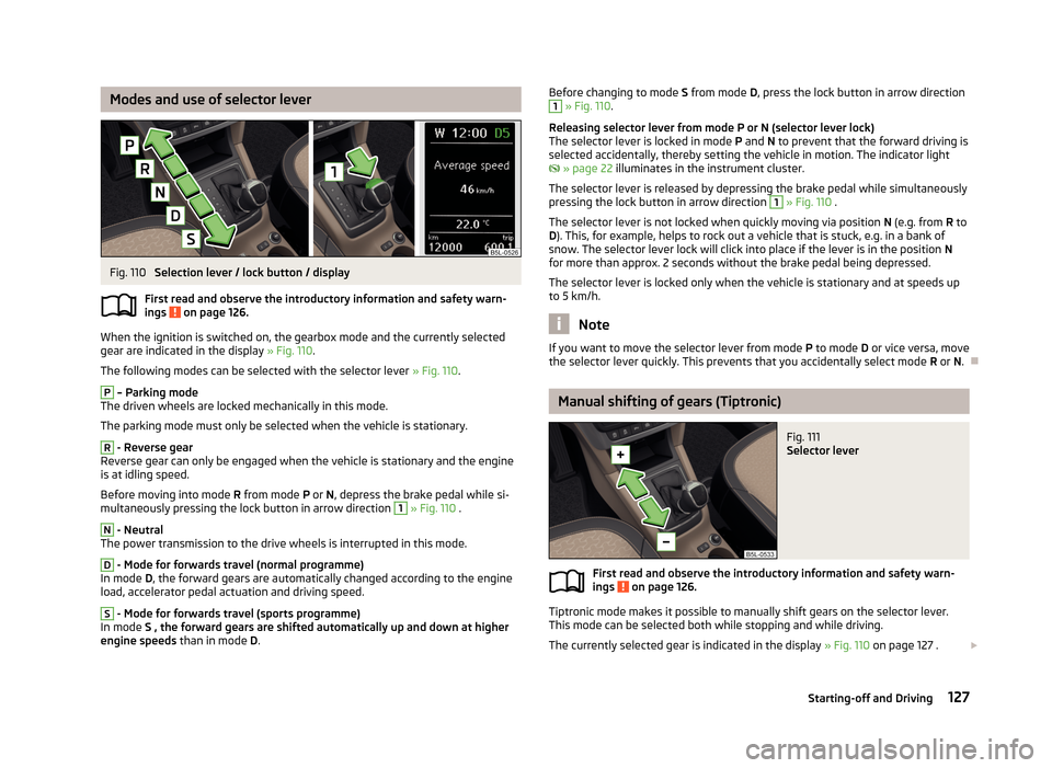
Modes and use of selector leverFig. 110
Selection lever / lock button / display
First read and observe the introductory information and safety warn- ings
on page 126.
When the ignition is switched on, the gearbox mode and the currently selected
gear are indicated in the display » Fig. 110.
The following modes can be selected with the selector lever » Fig. 110.
P
– Parking mode
The driven wheels are locked mechanically in this mode.
The parking mode must only be selected when the vehicle is stationary.
R
- Reverse gear
Reverse gear can only be engaged when the vehicle is stationary and the engine
is at idling speed.
Before moving into mode R from mode P or N, depress the brake pedal while si-
multaneously pressing the lock button in arrow direction
1
» Fig. 110 .
N
- Neutral
The power transmission to the drive wheels is interrupted in this mode.
D
- Mode for forwards travel (normal programme)
In mode D, the forward gears are automatically changed according to the engine
load, accelerator pedal actuation and driving speed.
S
- Mode for forwards travel (sports programme)
In mode S , the forward gears are shifted automatically up and down at higher
engine speeds than in mode D.
Before changing to mode S from mode D, press the lock button in arrow direction1 » Fig. 110 .
Releasing selector lever from mode P or N (selector lever lock)
The selector lever is locked in mode P and N to prevent that the forward driving is
selected accidentally, thereby setting the vehicle in motion. The indicator light
» page 22 illuminates in the instrument cluster.
The selector lever is released by depressing the brake pedal while simultaneously
pressing the lock button in arrow direction 1
» Fig. 110 .
The selector lever is not locked when quickly moving via position N (e.g. from R to
D ). This, for example, helps to rock out a vehicle that is stuck, e.g. in a bank of
snow. The selector lever lock will click into place if the lever is in the position N
for more than approx. 2 seconds without the brake pedal being depressed.
The selector lever is locked only when the vehicle is stationary and at speeds up
to 5 km/h.
Note
If you want to move the selector lever from mode P to mode D or vice versa, move
the selector lever quickly. This prevents that you accidentally select mode R or N.
Manual shifting of gears (Tiptronic)
Fig. 111
Selector lever
First read and observe the introductory information and safety warn-
ings on page 126.
Tiptronic mode makes it possible to manually shift gears on the selector lever.
This mode can be selected both while stopping and while driving.
The currently selected gear is indicated in the display » Fig. 110 on page 127 .
127Starting-off and Driving
Page 139 of 266

Assist systems
Brake assist systems
Introduction
This chapter contains information on the following subjects:
Electronic Stability Control (ESC)
136
Antilock brake system (ABS)
137
Traction Control System (TCS)
137
Electronic Differential Lock (EDL)
137
Driver Steering Recommendation (DSR)
137
Hydraulic Brake Assist (HBA)
137
Hill Hold Control (HHC)
138WARNING■ A lack of fuel can cause irregular engine running or cause the engine to shut
down. The brake assist systems would then fail to function – risk of accident!■
Adjust the speed and driving style to the current visibility, weather, road and
traffic conditions. The increased safety provided by the brake assist systems
must not tempt you to take safety risks – risk of accident!
■
In the event of an ABS fault, visit a specialist garage immediately. Adjust
your style of driving according to the damage to the ABS, as you will not know
the exact extent of the damage or the extent to which this is limiting the
braking efficiency.
CAUTION
■ All four wheels must be fitted with the same tyres approved by the manufactur-
er to ensure the brake assist systems operate correctly.■
Changes to the vehicle (e.g. to the engine, brakes, chassis) can influence the
functionality of the brake assist systems » page 184, Service work, adjustments
and technical alterations .
■
If a fault occurs in the ABS system, the ESC, ASR and EDL will also not work. An
ABS fault is indicated by the warning light » page 19 .
Electronic Stability Control (ESC)Fig. 116
ESC system: TCS button
First read and observe the introductory information and safety warn-
ings on page 136.
The ESC system helps improve control of the vehicle in situations where it is be-
ing operated at its dynamic limits, such as a sudden change to the direction of
travel. The risk of skidding is reduced and your car thus offers greater driving sta-
bility depending on the conditions of the road surface.
The ESC system is automatically activated each time the ignition is switched on.The direction which the driver wishes to take is determined based on the steering angle and the speed of the vehicle and is constantly compared with the actual
behaviour of the vehicle. In the event of deviations, such as the car beginning to
skid, the ESC system will automatically brake the appropriate wheel.
During an intervention of the system, the indicator light
flashes in the instru-
ment cluster.
The following systems are integrated into the Electronic Stability Control (ESC).
› Antilock Brake System (ABS)
» page 137.
› Traction control (TCS)
» page 137.
› Electronic Differential Lock (EDL)
» page 137.
› Driver Steering Recommendation (DSR)
» page 137.
› Hydraulic Brake Assist (HBA)
» page 137.
› Hill Hold Control (HHC)
» page 138.
› Trailer stabilisation (TSA)
» page 158.
The ESC system cannot be deactivated. The
» Fig. 116 symbol button can only
be used to deactivate the ASR.
The warning light lights up in the instrument cluster when the TCR is deactiva-
ted.
136Driving