sensor SKODA YETI 2013 1.G / 5L User Guide
[x] Cancel search | Manufacturer: SKODA, Model Year: 2013, Model line: YETI, Model: SKODA YETI 2013 1.G / 5LPages: 266, PDF Size: 26.71 MB
Page 55 of 266
The daytime running lights are switched on automatically if the following condi-tions are met:
The light switch is in the position » Fig. 27 on page 49.
The visibility in the vehicle environment is reduced. The ignition is switched off.
The parking aid is activated.
The function switches on the following light, depending on the equipment fit- ted.
› Parking lights
› Low beam
› Entry lighting in the exterior mirrors
› Licence plate light
The light is controlled on the basis of information that is collected from the holder
mounted in the rear-view mirror sensor » page 49 .
COMING HOME
The light turns on automatically when you open the driver's door on (within 60
seconds of turning off the ignition).
The light turns off 10 seconds after closing all the doors and the boot lid or after
the pre-set time has expired.
If a door or the boot lid remains open, the light goes out after 60 seconds.
LEAVING HOME
The light turns on automatically after the vehicle is unlocked with the remote
control.
The light turns off after 10 seconds or after a pre-set time or after the vehicle is
locked.
If no door is opened, the vehicle is locked automatically after 30 seconds.
Activate/deactivate the function
The functions and settings of the illumination time can be activated/deactivated via the MAXI DOT display in the menu items Coming Home or Leaving
Home » page 29 .
CAUTION
■
Do not attach any stickers or similar objects in front of the light sensor on the
windscreen to avoid impairing the function or its reliability.■
If this function is activated constantly, the battery will be heavily discharged
particularly in short-haul traffic.
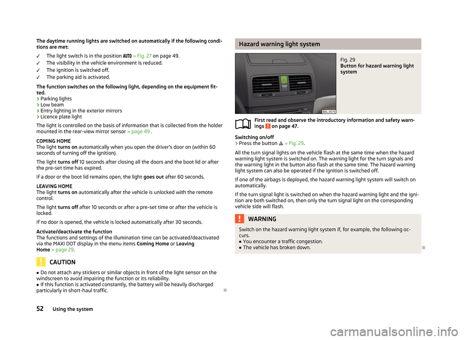
Hazard warning light systemFig. 29
Button for hazard warning light
system
First read and observe the introductory information and safety warn-
ings on page 47.
Switching on/off
›
Press the button
» Fig. 29 .
All the turn signal lights on the vehicle flash at the same time when the hazard
warning light system is switched on. The warning light for the turn signals and
the warning light in the button also flash at the same time. The hazard warning
light system can also be operated if the ignition is switched off.
If one of the airbags is deployed, the hazard warning light system will switch on
automatically.
If the turn signal light is switched on when the hazard warning light and the igni- tion are both switched on, then only the turn signal light on the corresponding
vehicle side will flash.
WARNINGSwitch on the hazard warning light system if, for example, the following oc-
curs.■
You encounter a traffic congestion.
■
The vehicle has broken down.
52Using the system
Page 62 of 266
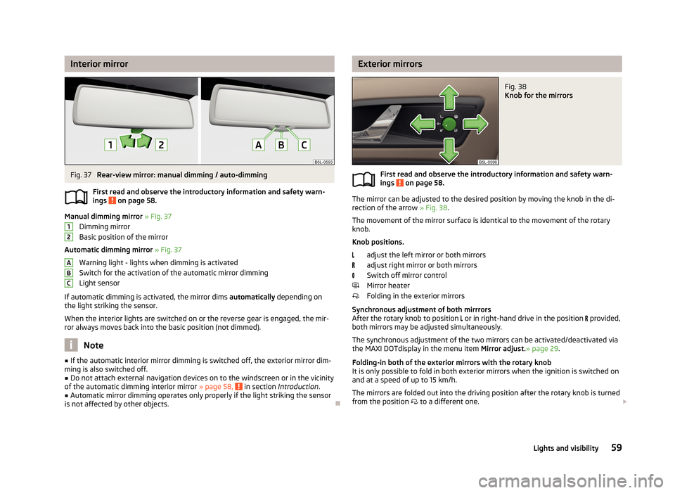
Interior mirrorFig. 37
Rear-view mirror: manual dimming / auto-dimming
First read and observe the introductory information and safety warn- ings
on page 58.
Manual dimming mirror » Fig. 37
Dimming mirror
Basic position of the mirror
Automatic dimming mirror » Fig. 37
Warning light - lights when dimming is activated Switch for the activation of the automatic mirror dimmingLight sensor
If automatic dimming is activated, the mirror dims automatically depending on
the light striking the sensor.
When the interior lights are switched on or the reverse gear is engaged, the mir- ror always moves back into the basic position (not dimmed).
Note
■ If the automatic interior mirror dimming is switched off, the exterior mirror dim-
ming is also switched off.■
Do not attach external navigation devices on to the windscreen or in the vicinity
of the automatic dimming interior mirror » page 58, in section Introduction .
■
Automatic mirror dimming operates only properly if the light striking the sensor
is not affected by other objects.
12ABCExterior mirrorsFig. 38
Knob for the mirrors
First read and observe the introductory information and safety warn-
ings on page 58.
The mirror can be adjusted to the desired position by moving the knob in the di-
rection of the arrow » Fig. 38.
The movement of the mirror surface is identical to the movement of the rotary
knob.
Knob positions. adjust the left mirror or both mirrors
adjust right mirror or both mirrors
Switch off mirror control
Mirror heater
Folding in the exterior mirrors
Synchronous adjustment of both mirrrors
After the rotary knob to position
or in right-hand drive in the position
provided,
both mirrors may be adjusted simultaneously.
The synchronous adjustment of the two mirrors can be activated/deactivated via
the MAXI DOTdisplay in the menu item Mirror adjust.» page 29.
Folding-in both of the exterior mirrors with the rotary knob
It is only possible to fold in both exterior mirrors when the ignition is switched on and at a speed of up to 15 km/h.
The mirrors are folded out into the driving position after the rotary knob is turned from the position
to a different one.
59Lights and visibility
Page 96 of 266
Note■Do not cover the air outlet vents with any objects, of any kind.■The air outlet vents 6 » Fig. 92 are only fitted on vehicles with the higher centre
console.
Recirculation
First read and observe the introductory information and safety warn-ings
on page 91.
Recirculated air mode prevents polluted air outside the vehicle from getting into
the vehicle, e.g. when driving through a tunnel or in a traffic jam.
In recirculated air mode air is sucked out of the interior of the vehicle and thenfed back into the interior.
Heating and air conditioning (manual air conditioning)
To turn the recirculation mode on or off, press the Symbol key
.
The air recirculation mode is automatically turned off by turning the air distribu-
tion control
C
to position
» Fig. 93 on page 94 or » Fig. 94 on page 94 .
Recirculated air mode can be switched on again from this position by repeatedly
pressing the symbol button
.
Climatronic (automatic air conditioning)
To turn the recirculation mode on, press the Symbol key
repeatedly until the
indicator light is lit on the left side of the button.
To activate the automatic recirculation mode, press the Symbol key
repeat-
edly until the indicator light is lit on the right side of the button.
Climatronic has an air quality sensor for the detection of the pollutant concentra-
tion in the sucked-in air.
If a considerable increase in concentration of pollutants is recognised by the air
quality sensor, recirculated air mode will temporarily be switched on.
If the concentration of pollutants decreases to the normal level, the air distribu-tion control is automatically switched off so that fresh air can be guided into the
vehicle interior.
If the air quality sensor does not automatically switch on the recirculated air
mode in the event of an unpleasant odour, you can switch it on yourself by press-
ing the button . The indicator light lights up in the button on the left side.
To
turn off the air recirculation or to deactivate the automatic air recirculations ,
press the button of press the symbol button repeatedly until the warning
lights in the button go out.WARNINGNever leave recirculated air mode switched on over a longer period of time, as
“stale air” can cause driver and passenger fatigue, reduce attention levels and
also cause the windows to mist up. The risk of having an accident increases.
Switch off recirculated air mode as soon as the windows start to mist up.
CAUTION
We recommend not smoking in the vehicle when the recirculating air operation is switched on. The smoke sucked from inside the vehicle is deposited on the evap-orator of the air conditioner. This produces a permanent odour when the air con-
ditioning system is operating which can only be eliminated through considerable effort and expense (replacement of compressor).
Note
The automatic air distribution control operates only if the outside temperature is
higher than approx. 2 °C.
93Heating and air-conditioning
Page 98 of 266
NoteThe warning light in the button lights after activation, even if not all of the
conditions for the function of the cooling system have been met. By lighting up of the indicator light in the button, the operational readiness of the cooling system
is signalled.
Climatronic (automatic air conditioning)
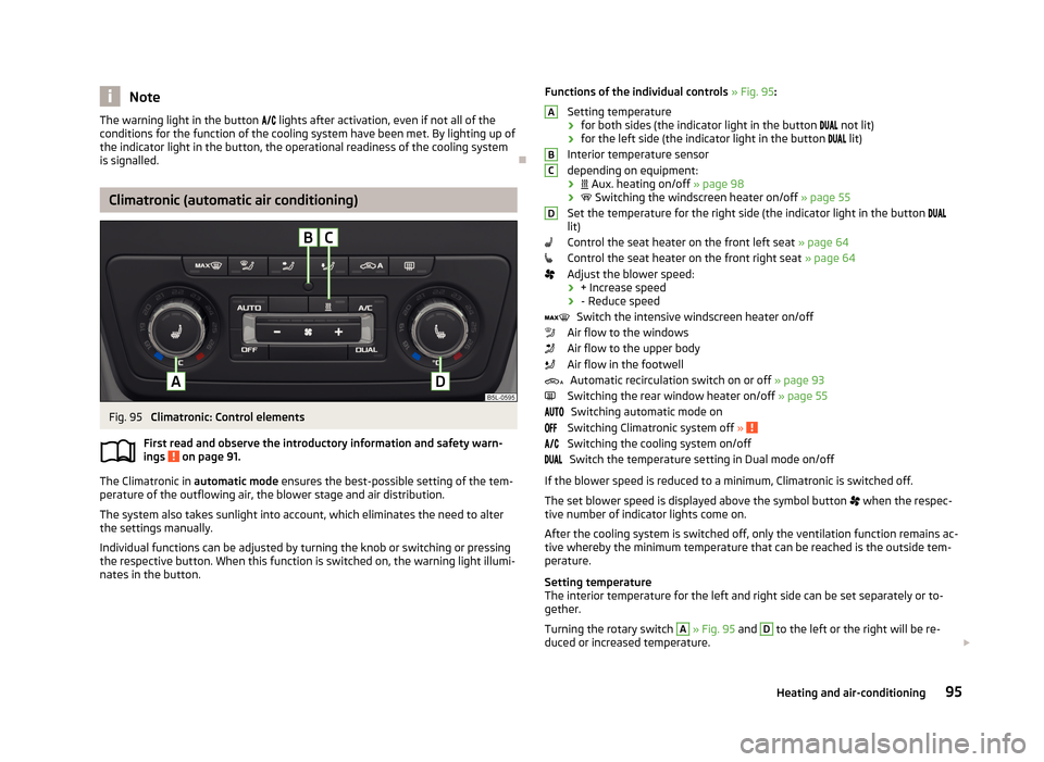
Fig. 95
Climatronic: Control elements
First read and observe the introductory information and safety warn- ings
on page 91.
The Climatronic in automatic mode ensures the best-possible setting of the tem-
perature of the outflowing air, the blower stage and air distribution.
The system also takes sunlight into account, which eliminates the need to alterthe settings manually.
Individual functions can be adjusted by turning the knob or switching or pressing the respective button. When this function is switched on, the warning light illumi-
nates in the button.
Functions of the individual controls » Fig. 95 :
Setting temperature
› for both sides (the indicator light in the button
not lit)
› for the left side (the indicator light in the button
lit)
Interior temperature sensor
depending on equipment:
›
Aux. heating on/off » page 98
›
Switching the windscreen heater on/off » page 55
Set the temperature for the right side (the indicator light in the button
lit)
Control the seat heater on the front left seat » page 64
Control the seat heater on the front right seat » page 64
Adjust the blower speed:
› + Increase speed
› - Reduce speed
Switch the intensive windscreen heater on/off
Air flow to the windows
Air flow to the upper body
Air flow in the footwell
Automatic recirculation switch on or off » page 93
Switching the rear window heater on/off » page 55
Switching automatic mode on
Switching Climatronic system off »
Switching the cooling system on/off
Switch the temperature setting in Dual mode on/off
If the blower speed is reduced to a minimum, Climatronic is switched off. The set blower speed is displayed above the symbol button
when the respec-
tive number of indicator lights come on.
After the cooling system is switched off, only the ventilation function remains ac-tive whereby the minimum temperature that can be reached is the outside tem-
perature.
Setting temperature
The interior temperature for the left and right side can be set separately or to-
gether.
Turning the rotary switch
A
» Fig. 95 and
D
to the left or the right will be re-
duced or increased temperature.
ABCD95Heating and air-conditioning
Page 99 of 266
The interior temperature can be set between +18 °C and +26 ℃. The interior tem-
perature is regulated automatically within this range.
If a temperature lower than +18 °C is selected, a blue symbol lights up at the start
of the numerical scale.
If a temperature higher than +26 °C is selected, a red symbol lights up at the start
of the numerical scale.
At both end positions, Climatronic runs at maximum cooling/heating output and
the temperature is automatically not regulated.
Controlling blower
The Climatronic system controls the blower stages automatically in line with the
interior temperature. However, the blower stages can be manually adapted to
suit your particular needs.
Automatic mode
The automatic mode is used in order to maintain a constant temperature and to
demist the windows in the interior of the car.
If the warning light in the top right corner of the button
lights up, the Clima-
tronic operates in “HIGH”-mode. The “HIGH” mode is the standard setting of the
Climatronic.
Upon pressing the
button again, the Climatronic switches to “LOW”-mode
and the indicator light in the top left corner lights up. The Climatronic uses only in this mode the lower blower speed. However taking into account the noise level,
this is more comfortable, yet be aware that the effectiveness of the air condition-
ing system is reduced particularly if the vehicle is fully occupied.
By pressing the button
again, it is changed to “HIGH”-mode.
Automatic mode is switched off by pressing one of the buttons for the air distri- bution or by increasing/decreasing the blower speed. The temperature is never-
theless regulated.WARNING■ Do not switch off the Climatronic system for longer than necessary.■Switch on the Climatronic system as soon as the windows mist up.Note■Do not stick anything onto or cover the interior temperature sensor B » Fig. 95
as this could impair the functioning of the Climatronic.■
On vehicles equipped with a factory-fitted radio or radio navigation system, the
Climatronic information is also shown on their displays. This function can be
switched off, see » operating instructions for the radio or navigation system .
Note
If the windscreen mists up, press the symbol button . Press the button
once the windscreen has demisted.
Using the air conditioning system economically
First read and observe the introductory information and safety warn-ings
on page 91.
The air conditioning system compressor uses power from the engine when in
cooling mode, which will affect the fuel consumption.
It recommended to open the windows or the doors of a vehicle for which the inte-rior has been strongly heated through the effect of direct sunlight in order to al-
low the heated air to escape.
The cooling system should not be on if the windows are open.
If the desired interior temperature can be achieved without switching the cooling
system on, then we do not recommend turning this on.
For the sake of the environment
Pollutant emissions are also reduced when fuel is saved » page 130, Economical
driving and environmental sustainability .
96Using the system
Page 143 of 266
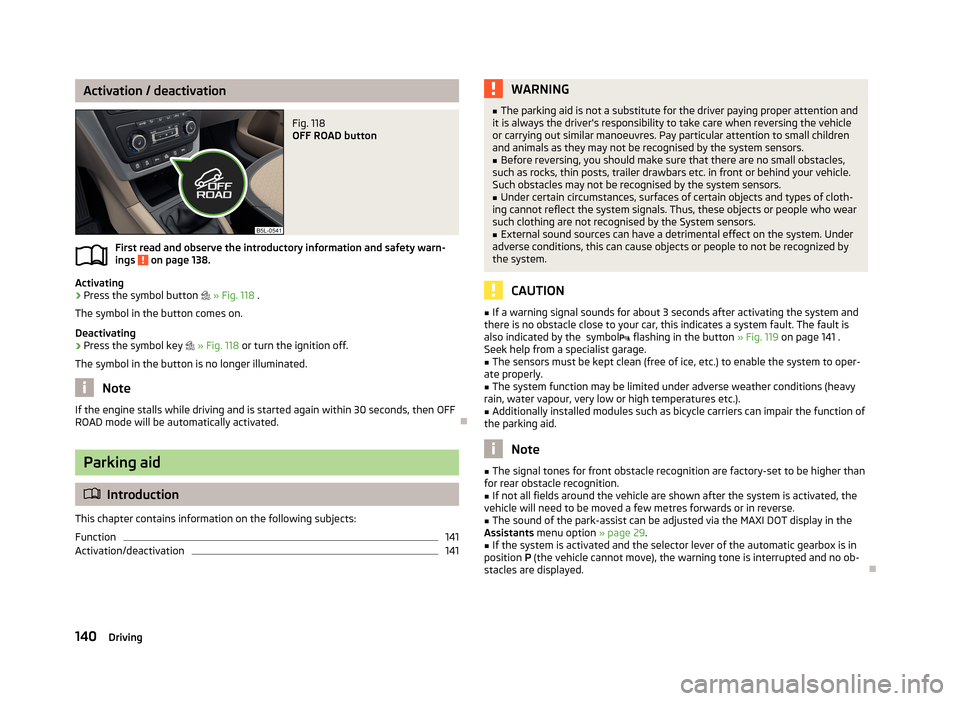
Activation / deactivationFig. 118
OFF ROAD button
First read and observe the introductory information and safety warn-ings on page 138.
Activating
›
Press the symbol button
» Fig. 118 .
The symbol in the button comes on.
Deactivating
›
Press the symbol key
» Fig. 118 or turn the ignition off.
The symbol in the button is no longer illuminated.
Note
If the engine stalls while driving and is started again within 30 seconds, then OFF
ROAD mode will be automatically activated.
Parking aid
Introduction
This chapter contains information on the following subjects:
Function
141
Activation/deactivation
141WARNING■ The parking aid is not a substitute for the driver paying proper attention and
it is always the driver's responsibility to take care when reversing the vehicle
or carrying out similar manoeuvres. Pay particular attention to small children
and animals as they may not be recognised by the system sensors.■
Before reversing, you should make sure that there are no small obstacles,
such as rocks, thin posts, trailer drawbars etc. in front or behind your vehicle.
Such obstacles may not be recognised by the system sensors.
■
Under certain circumstances, surfaces of certain objects and types of cloth-
ing cannot reflect the system signals. Thus, these objects or people who wear such clothing are not recognised by the System sensors.
■
External sound sources can have a detrimental effect on the system. Under
adverse conditions, this can cause objects or people to not be recognized by
the system.
CAUTION
■ If a warning signal sounds for about 3 seconds after activating the system and
there is no obstacle close to your car, this indicates a system fault. The fault is
also indicated by the symbol flashing in the button » Fig. 119 on page 141 .
Seek help from a specialist garage.■
The sensors must be kept clean (free of ice, etc.) to enable the system to oper-
ate properly.
■
The system function may be limited under adverse weather conditions (heavy
rain, water vapour, very low or high temperatures etc.).
■
Additionally installed modules such as bicycle carriers can impair the function of
the parking aid.
Note
■ The signal tones for front obstacle recognition are factory-set to be higher than
for rear obstacle recognition.■
If not all fields around the vehicle are shown after the system is activated, the
vehicle will need to be moved a few metres forwards or in reverse.
■
The sound of the park-assist can be adjusted via the MAXI DOT display in the
Assistants menu option » page 29.
■
If the system is activated and the selector lever of the automatic gearbox is in
position P (the vehicle cannot move), the warning tone is interrupted and no ob-
stacles are displayed.
140Driving
Page 144 of 266
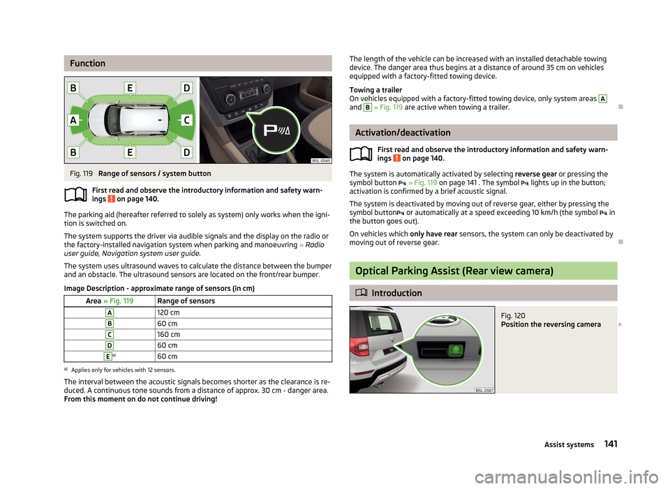
FunctionFig. 119
Range of sensors / system button
First read and observe the introductory information and safety warn- ings
on page 140.
The parking aid (hereafter referred to solely as system) only works when the igni- tion is switched on.
The system supports the driver via audible signals and the display on the radio or
the factory-installed navigation system when parking and manoeuvring » Radio
user guide, Navigation system user guide.
The system uses ultrasound waves to calculate the distance between the bumper
and an obstacle. The ultrasound sensors are located on the front/rear bumper.
Image Description - approximate range of sensors (in cm)
Area » Fig. 119Range of sensorsA120 cmB60 cmC160 cmD60 cmEa)60 cma)
Applies only for vehicles with 12 sensors.
The interval between the acoustic signals becomes shorter as the clearance is re- duced. A continuous tone sounds from a distance of approx. 30 cm - danger area.
From this moment on do not continue driving!
The length of the vehicle can be increased with an installed detachable towing
device. The danger area thus begins at a distance of around 35 cm on vehicles
equipped with a factory-fitted towing device.
Towing a trailer
On vehicles equipped with a factory-fitted towing device, only system areas A
and
B
» Fig. 119 are active when towing a trailer.
Activation/deactivation
First read and observe the introductory information and safety warn-
ings
on page 140.
The system is automatically activated by selecting reverse gear or pressing the
symbol button
» Fig. 119 on page 141 . The symbol
lights up in the button;
activation is confirmed by a brief acoustic signal.
The system is deactivated by moving out of reverse gear, either by pressing thesymbol button
or automatically at a speed exceeding 10 km/h (the symbol
in
the button goes out).
On vehicles which only have rear sensors, the system can only be deactivated by
moving out of reverse gear.
Optical Parking Assist (Rear view camera)
Introduction
Fig. 120
Position the reversing camera 141Assist systems
Page 145 of 266
This chapter contains information on the following subjects:
Orientation lines and monitored area142
Switching on/off
143
Optical Parking Assistant (hereinafter only as a system) supports the driver when
parking and manoeuvring.
The display of factory-installed navigation system shows the area behind the ve- hicle along with orientation lines » Fig. 121 on page 142 .
The area behind the vehicle is monitored by a camera » Fig. 120 .
The system only operates if the ignition is switched on. More information about displaying and operating in the Display » Operating in-
structions for the navigation system .
WARNING■
The system can not replace the driver's attention. Careless or uncontrolled
use of the system can cause accidents and serious injuries.■
Adjust the speed and driving style to the current visibility, weather, road and
traffic conditions.
■
Make sure that the camera lens is not dirty or covered, otherwise the sys-
tem function can be significantly impaired. For information on clean-
ing » page 191 , Camera lens
■
The camera lens distorts and enlarges the field of view of the difference in
eye sight. Objects are displayed deformed.
CAUTION
■ The system can be used only if tailgate is fully closed.■Some items, such as thin columns, chain link fences or lattice may not be repre-
sented adequately in terms of display resolution.■
It is only a two-dimensional display. Therefore, protruding objects or roadway
depressions, for example, may not be recognised due to lack of space depth.
■
In a crash or damage the vehicle's rear camera can possibly deviate from the
correct position. If this is the case, have the sensor checked by a specialist ga-
rage.
CAUTIONWe recommend that you do not use the system in the following situations.■The display is poor, such as when visibility is poor or in the event of a dirty lens.■
The rear of the vehicle is heavily loaded (the area displayed behind the vehicle is
too short).
CAUTION
The objects shown in the display can be closer or even further away than they ap-
pear. This is especially the case in the following situations.■
When driving from a horizontal surface into a slope or a depression.
■
When driving from a slope or a depression onto a horizontal surface.
Orientation lines and monitored area
Fig. 121
The navigation system display - Orientation strokes / monitored
area
First read and observe the introductory information and safety warn-
ings
on page 141.
Immovable yellow orientation bars are shown along with the monitored area be-
hind the vehicle on the display.
The distance between the lateral guide bars corresponds to the vehicle width in-
cluding mirrors.
Explanation of graphic The distance behind the vehicle is about 40 cm (clearance limit).The distance behind the vehicle is approximately 100 cm.
AB142Driving
Page 146 of 266
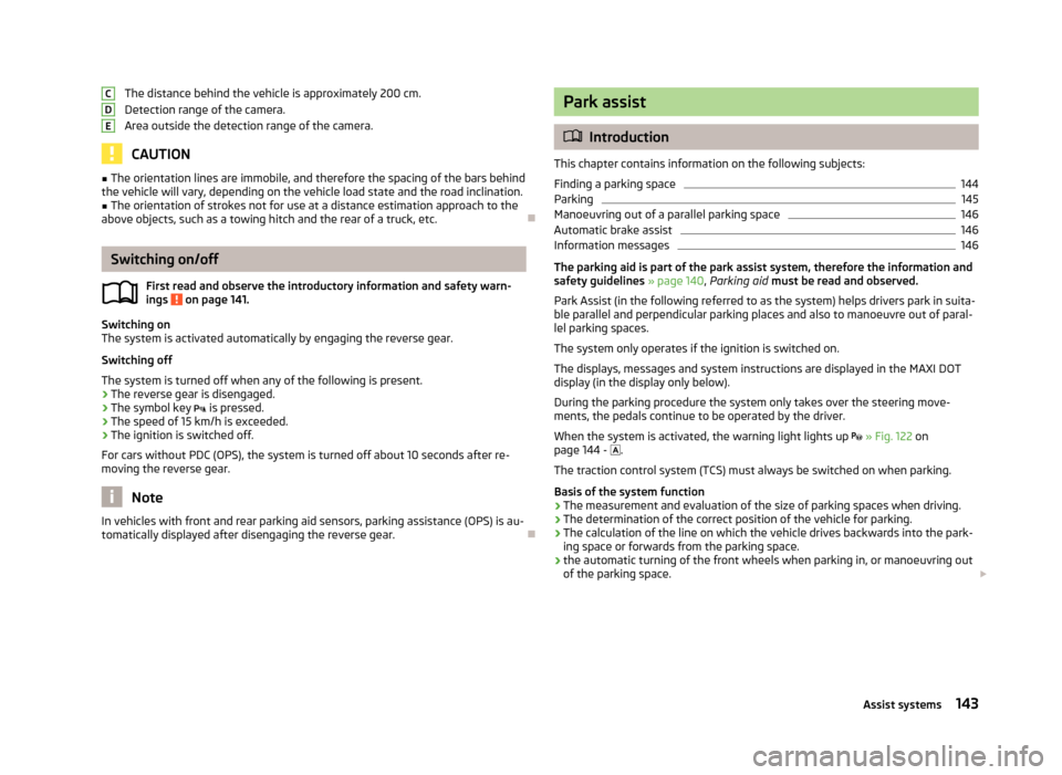
The distance behind the vehicle is approximately 200 cm.
Detection range of the camera.
Area outside the detection range of the camera.
CAUTION
■ The orientation lines are immobile, and therefore the spacing of the bars behind
the vehicle will vary, depending on the vehicle load state and the road inclination.■
The orientation of strokes not for use at a distance estimation approach to the
above objects, such as a towing hitch and the rear of a truck, etc.
Switching on/off
First read and observe the introductory information and safety warn-
ings
on page 141.
Switching on
The system is activated automatically by engaging the reverse gear.
Switching off
The system is turned off when any of the following is present.
› The reverse gear is disengaged.
› The symbol key
is pressed.
› The speed of 15 km/h is exceeded.
› The ignition is switched off.
For cars without PDC (OPS), the system is turned off about 10 seconds after re- moving the reverse gear.
Note
In vehicles with front and rear parking aid sensors, parking assistance (OPS) is au-
tomatically displayed after disengaging the reverse gear.CDEPark assist
Introduction
This chapter contains information on the following subjects:
Finding a parking space
144
Parking
145
Manoeuvring out of a parallel parking space
146
Automatic brake assist
146
Information messages
146
The parking aid is part of the park assist system, therefore the information and
safety guidelines » page 140, Parking aid must be read and observed.
Park Assist (in the following referred to as the system) helps drivers park in suita- ble parallel and perpendicular parking places and also to manoeuvre out of paral-lel parking spaces.
The system only operates if the ignition is switched on. The displays, messages and system instructions are displayed in the MAXI DOTdisplay (in the display only below).
During the parking procedure the system only takes over the steering move- ments, the pedals continue to be operated by the driver.
When the system is activated, the warning light lights up
» Fig. 122 on
page 144 -
.
The traction control system (TCS) must always be switched on when parking.
Basis of the system function › The measurement and evaluation of the size of parking spaces when driving.
› The determination of the correct position of the vehicle for parking.
› The calculation of the line on which the vehicle drives backwards into the park-
ing space or forwards from the parking space.
› the automatic turning of the front wheels when parking in, or manoeuvring out
of the parking space.
143Assist systems
Page 176 of 266
Side airbagsFig. 145
Position of the airbag in the front seat / back
Fig. 146
Inflated airbags
First read and observe the introductory information given on page 170.
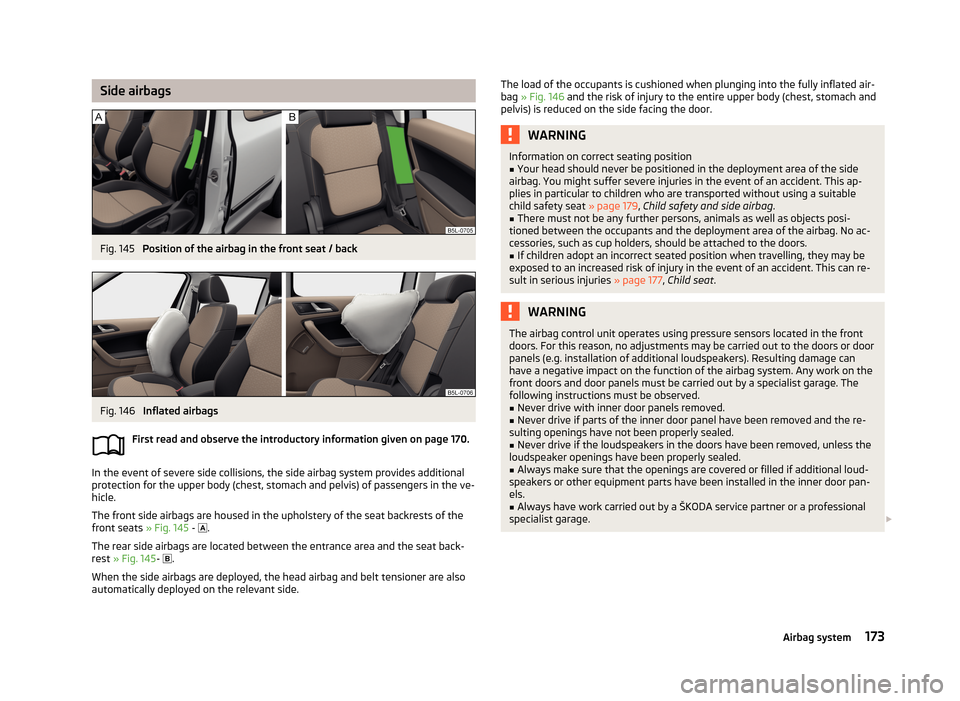
In the event of severe side collisions, the side airbag system provides additional
protection for the upper body (chest, stomach and pelvis) of passengers in the ve- hicle.
The front side airbags are housed in the upholstery of the seat backrests of the front seats » Fig. 145 -
.
The rear side airbags are located between the entrance area and the seat back-
rest » Fig. 145 -
.
When the side airbags are deployed, the head airbag and belt tensioner are also automatically deployed on the relevant side.
The load of the occupants is cushioned when plunging into the fully inflated air-
bag » Fig. 146 and the risk of injury to the entire upper body (chest, stomach and
pelvis) is reduced on the side facing the door.WARNINGInformation on correct seating position■Your head should never be positioned in the deployment area of the side
airbag. You might suffer severe injuries in the event of an accident. This ap- plies in particular to children who are transported without using a suitablechild safety seat » page 179, Child safety and side airbag .■
There must not be any further persons, animals as well as objects posi-
tioned between the occupants and the deployment area of the airbag. No ac-
cessories, such as cup holders, should be attached to the doors.
■
If children adopt an incorrect seated position when travelling, they may be
exposed to an increased risk of injury in the event of an accident. This can re-
sult in serious injuries » page 177, Child seat .
WARNINGThe airbag control unit operates using pressure sensors located in the front
doors. For this reason, no adjustments may be carried out to the doors or door
panels (e.g. installation of additional loudspeakers). Resulting damage can have a negative impact on the function of the airbag system. Any work on thefront doors and door panels must be carried out by a specialist garage. The
following instructions must be observed.■
Never drive with inner door panels removed.
■
Never drive if parts of the inner door panel have been removed and the re-
sulting openings have not been properly sealed.
■
Never drive if the loudspeakers in the doors have been removed, unless the
loudspeaker openings have been properly sealed.
■
Always make sure that the openings are covered or filled if additional loud-
speakers or other equipment parts have been installed in the inner door pan-
els.
■
Always have work carried out by a ŠKODA service partner or a professional
specialist garage.
173Airbag system