steering wheel SKODA YETI 2013 1.G / 5L User Guide
[x] Cancel search | Manufacturer: SKODA, Model Year: 2013, Model line: YETI, Model: SKODA YETI 2013 1.G / 5LPages: 266, PDF Size: 26.71 MB
Page 116 of 266
If the system does not recognise the command, it repeats the first part of thehelp thus enabling a new entry to be completed. After the 2nd error the systemrepeats the second part of the aid. After the 3rd failed attempt, the answer “ Can-
celled. ” is given and the dialogue is ended.
Storing voice recording for a contact
If automatic name recognition does not work reliably for some contacts, you can
choose to save your own voice tag for the contact in the Phone book - Voice tag -
Record menu item.
Your own voice tag can also be saved using the voice control in the FURTHER OP-
TIONS menu.
Multimedia
Introduction
This chapter contains information on the following subjects:
Music playback via Bluetooth ®
113
Operating the radio and navigation system on the multifunction steering
wheel
113
AUX- and MDIinputs
115CD change115DVD-preinstallation116
Music playback via Bluetooth ®
First read and observe the introductory information given on page 113.
The universal telephone preinstallation makes it possible to play back music via
Bluetooth ®
from devices such as MP3 players, mobile phones or notebooks.
To ensure that music can be played via Bluetooth ®
, you must first pair the device
with the hands-free system in the Phone - Bluetooth - Media player menu.
The music playback process is performed on the connected device.
The universal telephone preinstallation GSM II ensures that the music played back
via the hands-free system can be controlled with the remote control » page 112,
Voice commands - GSM II .
Note
The device being connected must support the Bluetooth ®
A2DP profile; refer to
the operating instructions for the relevant device being connected.
Operating the radio and navigation system on the multifunction steering wheel
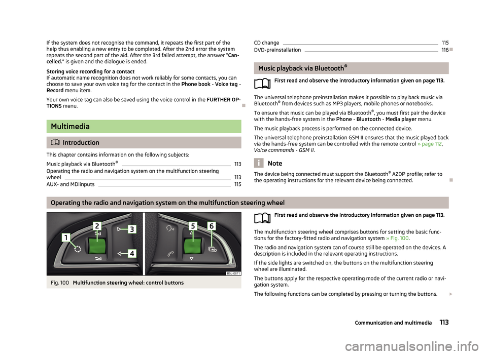
Fig. 100
Multifunction steering wheel: control buttons
First read and observe the introductory information given on page 113.
The multifunction steering wheel comprises buttons for setting the basic func-
tions for the factory-fitted radio and navigation system » Fig. 100.
The radio and navigation system can of course still be operated on the devices. A
description is included in the relevant operating instructions.
If the side lights are switched on, the buttons on the multifunction steeringwheel are illuminated.
The buttons apply for the respective operating mode of the current radio or navi- gation system.
The following functions can be completed by pressing or turning the buttons.
113Communication and multimedia
Page 120 of 266
Driving
Starting-off and Driving
Steering
Introduction
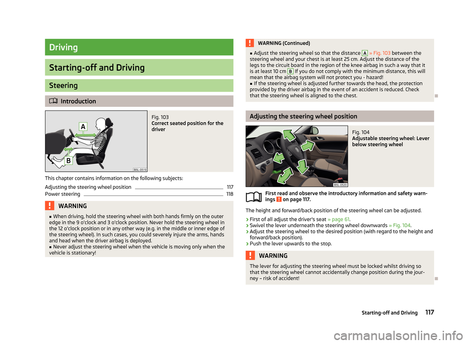
Fig. 103
Correct seated position for the
driver
This chapter contains information on the following subjects:
Adjusting the steering wheel position
117
Power steering
118WARNING■ When driving, hold the steering wheel with both hands firmly on the outer
edge in the 9 o'clock and 3 o'clock position. Never hold the steering wheel in
the 12 o'clock position or in any other way (e.g. in the middle or inner edge of
the steering wheel). In such cases, you could severely injure the arms, hands
and head when the driver airbag is deployed.■
Never adjust the steering wheel when the vehicle is moving only when the
vehicle is stationary!
WARNING (Continued)■ Adjust the steering wheel so that the distance A » Fig. 103 between the
steering wheel and your chest is at least 25 cm. Adjust the distance of the
legs to the circuit board in the region of the knee airbag in such a way that it
is at least 10 cm B
If you do not comply with the minimum distance, this will
mean that the airbag system will not protect you - hazard!
■
If the steering wheel is adjusted further towards the head, the protection
provided by the driver airbag in the event of an accident is reduced. Check that the steering wheel is aligned to the chest.
Adjusting the steering wheel position
Fig. 104
Adjustable steering wheel: Lever
below steering wheel
First read and observe the introductory information and safety warn-
ings on page 117.
The height and forward/back position of the steering wheel can be adjusted.
›
First of all adjust the driver's seat » page 61.
›
Swivel the lever underneath the steering wheel downwards » Fig. 104.
›
Adjust the steering wheel to the desired position (with regard to the height and
forward/back position).
›
Push the lever upwards to the stop.
WARNINGThe lever for adjusting the steering wheel must be locked whilst driving so
that the steering wheel cannot accidentally change position during the jour-
ney – risk of accident!
117Starting-off and Driving
Page 121 of 266
Power steeringFirst read and observe the introductory information and safety warn-ings
on page 117.
The power steering enables you to steer the vehicle with less physical force.
The power steering only works when the engine is running. It is still possible to fully steer the vehicle if the power steering fails or if the en-gine is not running (e.g. vehicle being towed in). However, greater physical effort is required to turn the steering wheel.
Starting and stopping the engine using the key
Introduction
This chapter contains information on the following subjects:
Electronic immobiliser
119
Ignition switch
119
Starting the engine
119
Stopping the engine
120
Starting and stopping the engine on vehicles with the KESSY system » page 120.
The engine can only be started with an appropriate original key.
The engine running noises may louder at first be louder for a short time after
starting the cold engine. This is quite normal and is not an operating problem.
WARNING■ When driving without the engine running, the ignition key must always be in
the position 2 » Fig. 105 on page 119 (ignition switched on). This position is
indicated by the illumination of certain indicator lights in the instrument clus-
ter. ■ If the key is not in position 2
, this could lead to unexpected the steering
locking - risk of accident!
■
Only pull the ignition key from the ignition lock when the vehicle has come
to a complete stop (by applying the handbrake). Otherwise, the steering could
be blocked – risk of accident!
■
When leaving the vehicle, the ignition must always be removed. This is par-
ticularly important if children are left in the vehicle. Children could otherwise
start the engine for example – risk of accident or injury!
■
Never leave the vehicle unattended with the engine running.
■
Never switch off the engine before the vehicle is stationary – risk of acci-
dent!
WARNING■ Never leave the engine running in unventilated or closed rooms. The ex-
haust gases from the engine contain substances such as odourless and col-
ourless carbon monoxide (a poisonous gas) – risk to life! ■ Carbon monoxide can cause unconsciousness and death.
CAUTION
■The starter must only be operated when the engine is not running and the vehi-
cle is at a standstill. The starter or engine may be damaged if the starter is activa- ted when the engine is running 3
» Fig. 105 on page 119.
■
Do not tow start the engine – there is a risk of damaging the engine and the
catalytic converter. The battery from another vehicle can be used as a jump-start
aid » page 226 , Jump-starting .
CAUTION
■
Avoid high engine revolutions, full throttle and high engine loads before the en-
gine has reached its operating temperature – risk of damaging the engine!■
Do not switch the engine off immediately at the end of your journey after the
engine has been operated over a prolonged period at high loads but leave it to
run at an idling speed for about 1 minute. This prevents any possible accumulation
of heat when the engine is switched off.
118Driving
Page 122 of 266
For the sake of the environmentDo not warm up the engine while the vehicle is stationary. If possible, start your
journey as soon as the engine has started. Through this the engine reaches its operating temperature more rapidly and the pollutant emissions are lower.
Note
After switching off the ignition, the radiator fan may intermittently continue to
operate for approx. 10 minutes.
Electronic immobiliser
First read and observe the introductory information and safety warn-
ings
on page 118.
An electronic chip is integrated in the head of the key. The immobiliser is deacti-
vated with the aid of this chip when the key is inserted in the ignition lock.
The electronic immobiliser is automatically activated when the ignition key is
withdrawn from the lock.
The engine will not start if a non-authorized ignition key is used.
The following message is shown in the information cluster display.
Immobilizer active.
IMMOBILIZER
Ignition switch
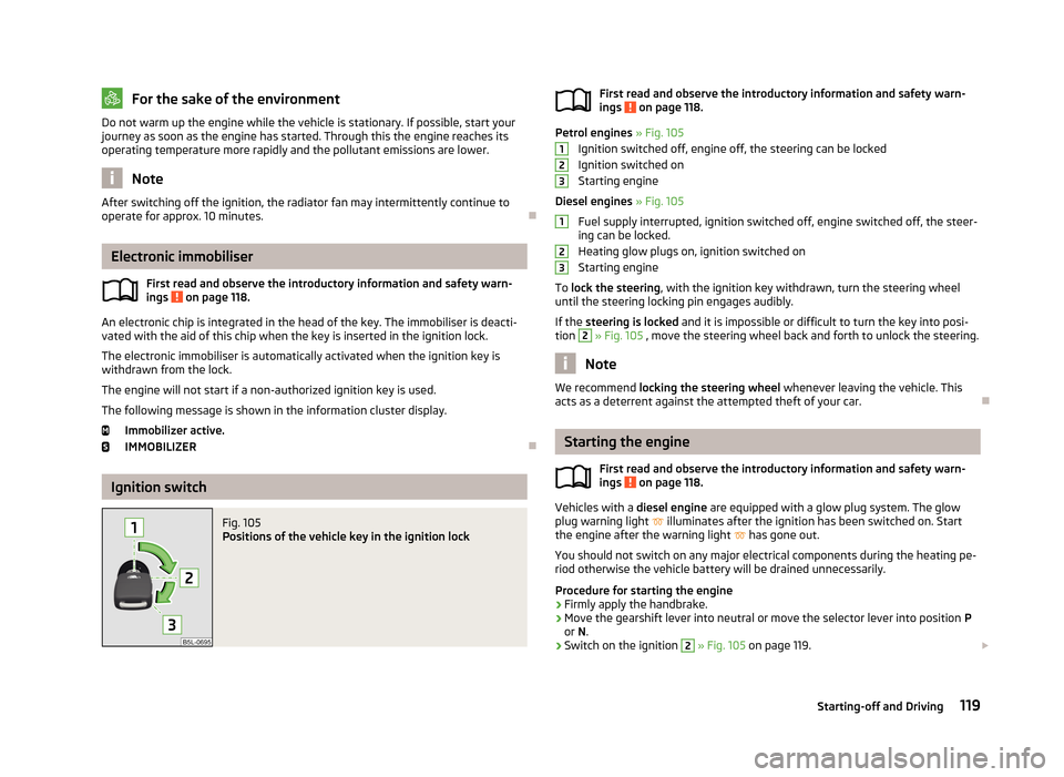
Fig. 105
Positions of the vehicle key in the ignition lockFirst read and observe the introductory information and safety warn-
ings on page 118.
Petrol engines » Fig. 105
Ignition switched off, engine off, the steering can be locked
Ignition switched on
Starting engine
Diesel engines » Fig. 105
Fuel supply interrupted, ignition switched off, engine switched off, the steer-
ing can be locked.
Heating glow plugs on, ignition switched on
Starting engine
To lock the steering , with the ignition key withdrawn, turn the steering wheel
until the steering locking pin engages audibly.
If the steering is locked and it is impossible or difficult to turn the key into posi-
tion
2
» Fig. 105 , move the steering wheel back and forth to unlock the steering.
Note
We recommend locking the steering wheel whenever leaving the vehicle. This
acts as a deterrent against the attempted theft of your car.
Starting the engine
First read and observe the introductory information and safety warn-
ings
on page 118.
Vehicles with a diesel engine are equipped with a glow plug system. The glow
plug warning light
illuminates after the ignition has been switched on. Start
the engine after the warning light
has gone out.
You should not switch on any major electrical components during the heating pe- riod otherwise the vehicle battery will be drained unnecessarily.
Procedure for starting the engine
›
Firmly apply the handbrake.
›
Move the gearshift lever into neutral or move the selector lever into position P
or N.
›
Switch on the ignition
2
» Fig. 105 on page 119.
123123119Starting-off and Driving
Page 125 of 266
If the driver's door is opened and the ignition is switched off afterwards, the
steering is only locked after the vehicle is locked.
Unlocking›
Open the driver's door and get into the vehicle.
›
Close the driver's door.
The steering is unlocked within 2 seconds.
If the system does not unlock the steering at the first time (for example when the
front wheels are in contact with an obstacle), then two more unlocking attempts
are performed automatically.
If the steering is still not unlocked, then the following message is displayed on
the display of the instrument cluster.
Move steering wheel!
MOVE STEERING
Slightly move the steering wheel and the system will make up to 3 more attempts
to unlock after 2 seconds. At the same time, the indicator light
flashes.
If the steering is still not unlocked, to try to eliminate the possible cause and then
repeat the unlocking attempt.
Switching on the ignition
First read and observe the introductory information and safety warn-
ings
on page 120.
›
Press the starter button » Fig. 106 on page 121 briefly.
The ignition is switched on.
Note
The ignition is switched on when indicated by the lighting up of certain indicator
lamps in the instrument cluster.Starting the engine
First read and observe the introductory information and safety warn-
ings
on page 120.
Vehicles with a diesel engine are equipped with a glow plug system. The glow
plug warning light illuminates after the ignition has been switched on. Start
the engine after the warning light has gone out.
You should not switch on any major electrical components during the heating pe- riod otherwise the vehicle battery will be drained unnecessarily.
Procedure for starting the engine
›
Firmly apply the handbrake.
›
Move the gearshift lever into neutral or move the selector lever into position P
or N.
›
Depress and hold the clutch pedal (vehicles with a manual gearbox) or brake
pedal (vehicles with an automatic gearbox) until the engine starts.
›
» Fig. 106 on page 121Press and hold 1)
the starter button until the engine starts.
›
Release the handbrake.
Vehicles with manual transmission
The engine will not start if the clutch pedal is not depressed.
The following message is shown in the information cluster display.
Depress clutch to start!
CLUTCH
Vehicles with automatic transmission The engine will not start if the brake pedal is not depressed.
The warning light
lights up in the instrument cluster and the following mes-
sage appears in the display.
Depress brake to start!
BRAKE
1)
On vehicles with the START-STOP system, it is sufficient to press the starter button briefly. The mo-
tor will then automatically start.
122Driving
Page 127 of 266
After emergency stop of the ignition, the steering is unlocked.
Brakes
Introduction
This chapter contains information on the following subjects:
Information on braking
124
Handbrake
125WARNING■ Greater physical effort is required for braking when the engine is switched
off – risk of accident!■
During the braking procedure on a vehicle with manual transmission, when
the vehicle is in gear and at low revs, press the clutch pedal. Otherwise, the
function of the brake booster may be impaired – risk of accident!
■
Never leave children unattended in the vehicle. The children might, for ex-
ample, release the handbrake or take the vehicle out of gear. The vehicle could then start to move – risk of accident!
WARNINGIn the event of damage occurring to the standard fitted front spoiler or the
retrofitting of another front spoiler, wheel hubs etc. » page 184, Service work,
adjustments and technical alterations , It must be ensured that the air supply
to the front brakes is not impaired. The front brakes may overheat which can
have a negative impact on the functioning of the braking system – risk of acci- dent!
CAUTION
■ Observe the recommendations on the new brake pads » page 130.■Never let the brakes slip with light pressure on the pedal if braking is not neces-
sary. This causes the brakes to overheat and can also result in a longer braking distance and excessive wear.
Information on braking
First read and observe the introductory information and safety warn-
ings
on page 124.
If the brakes are applied in full and the control unit for the braking system consid-
ers the situation to be dangerous for the following traffic, the brake light flashes
automatically.
After the speed was reduced below around 10 km/h or the vehicle was stopped,
the brake light stops flashing and the hazard warning light system switches on.
The hazard warning light system is switched off automatically after accelerating
or driving off again.
Before driving a long distance at a steep incline, reduce speed and shift into the
next lowest gear. As a result, the braking effect of the engine will be used, reduc- ing the load on the brakes. Any additional braking should be completed intermit-tently, not continuously.
Wear-and-tear
The wear of the brake pads is dependent on the operating conditions and driving style.
The brake pads wear more quickly if a lot of journeys are completed in towns and over short distances or if a very sporty style of driving is adopted.
If operated under severe conditions , the thickness of the brake pads must be
checked by a specialist garage between service appointments as well.
Wet roads or road salt
The performance of the brakes can be delayed as the brake discs and brake pads may be moist or have a coating of ice or layer of salt on them in winter. The
brakes are cleaned and dried by applying the brakes several times.
Corrosion
Corrosion on the brake discs and dirt on the bake pads occur if the vehicle has
been parked for a long period and if you do not make much use of the braking
system. The brakes are cleaned and dried by applying the brakes several times.
Faults in the brake surface
If it is found that the braking distance has suddenly become longer and that the
brake pedal can be depressed further, the brake system may be faulty.
Visit a specialist garage immediately and adjust your style of driving appropriate-ly, as you will not know the exact extent of the damage.
124Driving
Page 139 of 266

Assist systems
Brake assist systems
Introduction
This chapter contains information on the following subjects:
Electronic Stability Control (ESC)
136
Antilock brake system (ABS)
137
Traction Control System (TCS)
137
Electronic Differential Lock (EDL)
137
Driver Steering Recommendation (DSR)
137
Hydraulic Brake Assist (HBA)
137
Hill Hold Control (HHC)
138WARNING■ A lack of fuel can cause irregular engine running or cause the engine to shut
down. The brake assist systems would then fail to function – risk of accident!■
Adjust the speed and driving style to the current visibility, weather, road and
traffic conditions. The increased safety provided by the brake assist systems
must not tempt you to take safety risks – risk of accident!
■
In the event of an ABS fault, visit a specialist garage immediately. Adjust
your style of driving according to the damage to the ABS, as you will not know
the exact extent of the damage or the extent to which this is limiting the
braking efficiency.
CAUTION
■ All four wheels must be fitted with the same tyres approved by the manufactur-
er to ensure the brake assist systems operate correctly.■
Changes to the vehicle (e.g. to the engine, brakes, chassis) can influence the
functionality of the brake assist systems » page 184, Service work, adjustments
and technical alterations .
■
If a fault occurs in the ABS system, the ESC, ASR and EDL will also not work. An
ABS fault is indicated by the warning light » page 19 .
Electronic Stability Control (ESC)Fig. 116
ESC system: TCS button
First read and observe the introductory information and safety warn-
ings on page 136.
The ESC system helps improve control of the vehicle in situations where it is be-
ing operated at its dynamic limits, such as a sudden change to the direction of
travel. The risk of skidding is reduced and your car thus offers greater driving sta-
bility depending on the conditions of the road surface.
The ESC system is automatically activated each time the ignition is switched on.The direction which the driver wishes to take is determined based on the steering angle and the speed of the vehicle and is constantly compared with the actual
behaviour of the vehicle. In the event of deviations, such as the car beginning to
skid, the ESC system will automatically brake the appropriate wheel.
During an intervention of the system, the indicator light
flashes in the instru-
ment cluster.
The following systems are integrated into the Electronic Stability Control (ESC).
› Antilock Brake System (ABS)
» page 137.
› Traction control (TCS)
» page 137.
› Electronic Differential Lock (EDL)
» page 137.
› Driver Steering Recommendation (DSR)
» page 137.
› Hydraulic Brake Assist (HBA)
» page 137.
› Hill Hold Control (HHC)
» page 138.
› Trailer stabilisation (TSA)
» page 158.
The ESC system cannot be deactivated. The
» Fig. 116 symbol button can only
be used to deactivate the ASR.
The warning light lights up in the instrument cluster when the TCR is deactiva-
ted.
136Driving
Page 140 of 266
Antilock brake system (ABS)First read and observe the introductory information and safety warn-
ings
on page 136.
ABS prevents the wheels locking when braking. Thus helping the driver to main- tain control of the vehicle.
The intervention of the ABS is noticeable from the pulsating movements of the
brake pedal which is accompanied by noises.
When the ABS system is active, do not brake periodically or reduce the pressure on the brake pedal.
Traction Control System (TCS)
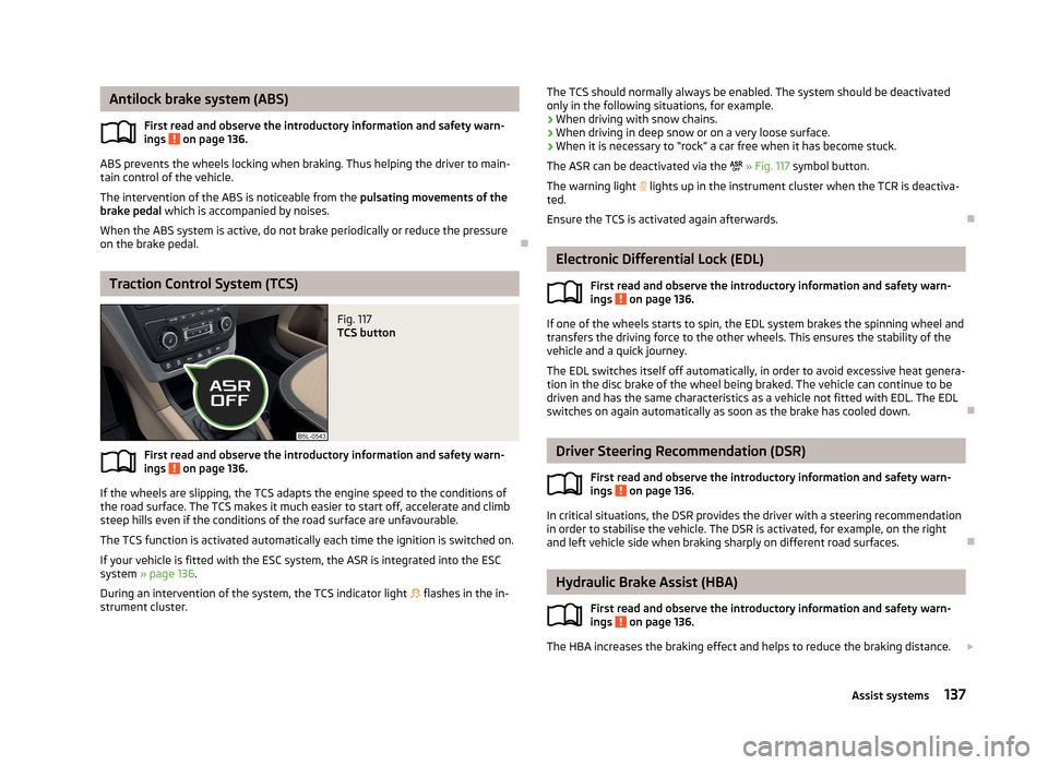
Fig. 117
TCS button
First read and observe the introductory information and safety warn- ings on page 136.
If the wheels are slipping, the TCS adapts the engine speed to the conditions ofthe road surface. The TCS makes it much easier to start off, accelerate and climb
steep hills even if the conditions of the road surface are unfavourable.
The TCS function is activated automatically each time the ignition is switched on.
If your vehicle is fitted with the ESC system, the ASR is integrated into the ESC
system » page 136 .
During an intervention of the system, the TCS indicator light flashes in the in-
strument cluster.
The TCS should normally always be enabled. The system should be deactivated
only in the following situations, for example.
› When driving with snow chains.
› When driving in deep snow or on a very loose surface.
› When it is necessary to “rock” a car free when it has become stuck.
The ASR can be deactivated via the
» Fig. 117 symbol button.
The warning light lights up in the instrument cluster when the TCR is deactiva-
ted.
Ensure the TCS is activated again afterwards.
Electronic Differential Lock (EDL)
First read and observe the introductory information and safety warn-
ings
on page 136.
If one of the wheels starts to spin, the EDL system brakes the spinning wheel and transfers the driving force to the other wheels. This ensures the stability of the
vehicle and a quick journey.
The EDL switches itself off automatically, in order to avoid excessive heat genera-
tion in the disc brake of the wheel being braked. The vehicle can continue to be
driven and has the same characteristics as a vehicle not fitted with EDL. The EDL switches on again automatically as soon as the brake has cooled down.
Driver Steering Recommendation (DSR)
First read and observe the introductory information and safety warn-ings
on page 136.
In critical situations, the DSR provides the driver with a steering recommendationin order to stabilise the vehicle. The DSR is activated, for example, on the right
and left vehicle side when braking sharply on different road surfaces.
Hydraulic Brake Assist (HBA)
First read and observe the introductory information and safety warn-ings
on page 136.
The HBA increases the braking effect and helps to reduce the braking distance.
137Assist systems
Page 146 of 266
The distance behind the vehicle is approximately 200 cm.
Detection range of the camera.
Area outside the detection range of the camera.
CAUTION
■ The orientation lines are immobile, and therefore the spacing of the bars behind
the vehicle will vary, depending on the vehicle load state and the road inclination.■
The orientation of strokes not for use at a distance estimation approach to the
above objects, such as a towing hitch and the rear of a truck, etc.
Switching on/off
First read and observe the introductory information and safety warn-
ings
on page 141.
Switching on
The system is activated automatically by engaging the reverse gear.
Switching off
The system is turned off when any of the following is present.
› The reverse gear is disengaged.
› The symbol key
is pressed.
› The speed of 15 km/h is exceeded.
› The ignition is switched off.
For cars without PDC (OPS), the system is turned off about 10 seconds after re- moving the reverse gear.
Note
In vehicles with front and rear parking aid sensors, parking assistance (OPS) is au-
tomatically displayed after disengaging the reverse gear.CDEPark assist
Introduction
This chapter contains information on the following subjects:
Finding a parking space
144
Parking
145
Manoeuvring out of a parallel parking space
146
Automatic brake assist
146
Information messages
146
The parking aid is part of the park assist system, therefore the information and
safety guidelines » page 140, Parking aid must be read and observed.
Park Assist (in the following referred to as the system) helps drivers park in suita- ble parallel and perpendicular parking places and also to manoeuvre out of paral-lel parking spaces.
The system only operates if the ignition is switched on. The displays, messages and system instructions are displayed in the MAXI DOTdisplay (in the display only below).
During the parking procedure the system only takes over the steering move- ments, the pedals continue to be operated by the driver.
When the system is activated, the warning light lights up
» Fig. 122 on
page 144 -
.
The traction control system (TCS) must always be switched on when parking.
Basis of the system function › The measurement and evaluation of the size of parking spaces when driving.
› The determination of the correct position of the vehicle for parking.
› The calculation of the line on which the vehicle drives backwards into the park-
ing space or forwards from the parking space.
› the automatic turning of the front wheels when parking in, or manoeuvring out
of the parking space.
143Assist systems
Page 147 of 266
WARNING■The system does not exempt the driver from his/her responsibility for park-
ing in and manoeuvring out of the parking space.■
External sound sources can have a detrimental effect on parking in and ma-
noeuvring out of the parking space. Under adverse conditions, this can cause
objects or people to not be recognized by the system.
■
When parking in, and manoeuvring out of parking spaces, the system auto-
matically executes quick steering movements. While it is doing so, do not place your hands between the steering wheel – risk of injury!
■
When parking or leaving a parking space on loose or slippery surfaces (grav-
el, snow, ice, etc.) you may stray from the calculated road because of the sur-
face conditions. Therefore we suggest that you do not use the system in such
situations.
CAUTION
■ If other vehicles are parked behind the kerb or on it, the system can also guide
your vehicle beyond the kerb or onto it. Ensure that the wheels or the wheel rims
of your vehicle are not damaged and if necessary intervene in time.■
Under certain circumstances, surfaces or structures of certain objects such as
wire mesh fences or powder snow cannot be recognised by the system.
■
The system function may be limited under adverse weather conditions (heavy
rain, water vapour, very low or high temperatures etc.).
■
The evaluation of the parking space and the parking procedure depends on the
circumference of the wheels on the vehicle. The system only works correctly if
the vehicle is fitted with the wheel size approved by the manufacturer.
■
If wheels other than those approved by the manufacturer are mounted, the re-
sulting position of the vehicle in the parking space can differ slightly. This can be avoided by readjusting the system at a specialist garage.
■
Under certain circumstances, the system may not function correctly, for exam-
ple, if the vehicle is fitted with snow chains or a temporary spare wheel.
Finding a parking spaceFig. 122
System button / display
First read and observe the introductory information and safety warn-
ings
on page 143.
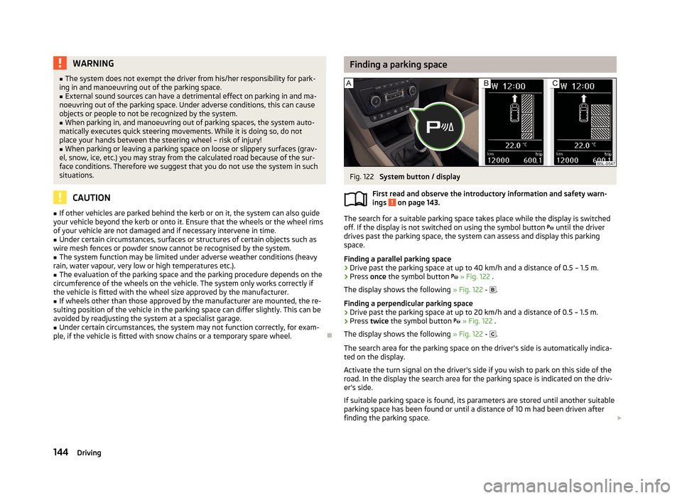
The search for a suitable parking space takes place while the display is switched
off. If the display is not switched on using the symbol button until the driver
drives past the parking space, the system can assess and display this parking
space.
Finding a parallel parking space
›
Drive past the parking space at up to 40 km/h and a distance of 0.5 – 1.5 m.
›
Press once the symbol button
» Fig. 122 .
The display shows the following » Fig. 122 -
.
Finding a perpendicular parking space
›
Drive past the parking space at up to 20 km/h and a distance of 0.5 – 1.5 m.
›
Press twice the symbol button
» Fig. 122 .
The display shows the following » Fig. 122 -
.
The search area for the parking space on the driver's side is automatically indica-
ted on the display.
Activate the turn signal on the driver's side if you wish to park on this side of the
road. In the display the search area for the parking space is indicated on the driv-
er's side.
If suitable parking space is found, its parameters are stored until another suitable
parking space has been found or until a distance of 10 m had been driven after
finding the parking space.
144Driving