fuel cap SKODA YETI 2013 1.G / 5L Owner's Manual
[x] Cancel search | Manufacturer: SKODA, Model Year: 2013, Model line: YETI, Model: SKODA YETI 2013 1.G / 5LPages: 266, PDF Size: 26.71 MB
Page 15 of 266
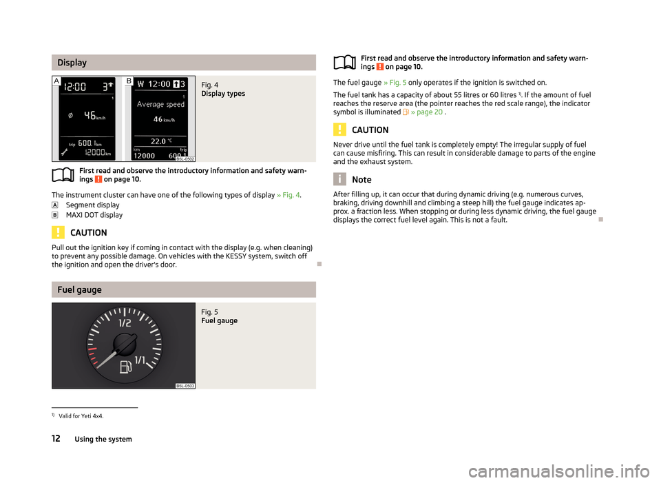
DisplayFig. 4
Display types
First read and observe the introductory information and safety warn-ings on page 10.
The instrument cluster can have one of the following types of display » Fig. 4.
Segment display
MAXI DOT display
CAUTION
Pull out the ignition key if coming in contact with the display (e.g. when cleaning)
to prevent any possible damage. On vehicles with the KESSY system, switch off
the ignition and open the driver's door.
Fuel gauge
Fig. 5
Fuel gaugeFirst read and observe the introductory information and safety warn- ings on page 10.
The fuel gauge » Fig. 5 only operates if the ignition is switched on.
The fuel tank has a capacity of about 55 litres or 60 litres 1)
. If the amount of fuel
reaches the reserve area (the pointer reaches the red scale range), the indicator
symbol is illuminated » page 20 .
CAUTION
Never drive until the fuel tank is completely empty! The irregular supply of fuel
can cause misfiring. This can result in considerable damage to parts of the engine
and the exhaust system.
Note
After filling up, it can occur that during dynamic driving (e.g. numerous curves,
braking, driving downhill and climbing a steep hill) the fuel gauge indicates ap-
prox. a fraction less. When stopping or during less dynamic driving, the fuel gauge displays the correct fuel level again. This is not a fault.
1)
Valid for Yeti 4x4.
12Using the system
Page 35 of 266
Unlocking and opening
Unlocking and locking
Introduction
This chapter contains information on the following subjects:
Vehicle key
33
Unlocking/locking with the key
33
Unlocking/locking with the remote control
34
Synchronising the remote control
34
Unlocking/locking – KESSY
35
Safe securing system
35
Individual settings
36
Locking/unlocking the vehicle from the inside
36
Child safety lock
37
Opening/closing a door
37
Your car is equipped with a central locking system.
The central locking system allows you to lock and unlock all doors, the fuel filler
flap 1)
and tailgate 2)
at the same time.
The safe securing system » page 35 is integrated in the central locking system.
Once the car is locked from the outside, the door locks 3)
are automatically blocked
by the safe securing system »
.
The following is true after unlocking 2)
.
› The doors, the boot lid and the fuel filler flap 1)
are unlocked.
› The interior light operated via the door contact illuminates.
› The safe securing system is switched off 3)
.
› The indicator light in the driver door stops flashing.
› The anti-theft alarm system is deactivated.
The following is true after locking 2)
.
› The doors, the boot lid and the fuel filler flap 1)
are locked.
› The interior light operated via the door contact goes out.
› The safe securing system is switched on 3)
.
› The indicator light in the driver door begins flashing.
› The anti-theft alarm system is activated.
Displaying an error
If the warning light in the driver's door initially flashes quickly for around 2 sec-
onds, and then lights up for 30 seconds without interruption before flashing
again slowly, you will need to seek the assistance of a specialist garage.WARNINGIf the car is locked and the safe securing system activated, no people must re-
main in the car as it will then not be possible to either unlock a door or open a
window from the inside. The locked doors make it more difficult for rescuers
to get into the vehicle in an emergency – risk to life!
Note
■ In the event of an accident in which the airbags are deployed, the locked doors
are automatically unlocked in order to enable rescuers to gain access to the vehi- cle.■
Only the driver's door can be unlocked or locked using the key if the central
locking system fails » page 33. The other doors and the boot lid can be emer-
gency locked or unlocked. ■ Emergency locking of the door » page 232.
■ Emergency unlocking of the boot lid » page 233.
1)
Applies to vehicles with a lockable fuel filler cap.
2)
Depending on the individual setting » page 36.
3)
This function only applies to certain countries.
32Using the system
Page 93 of 266
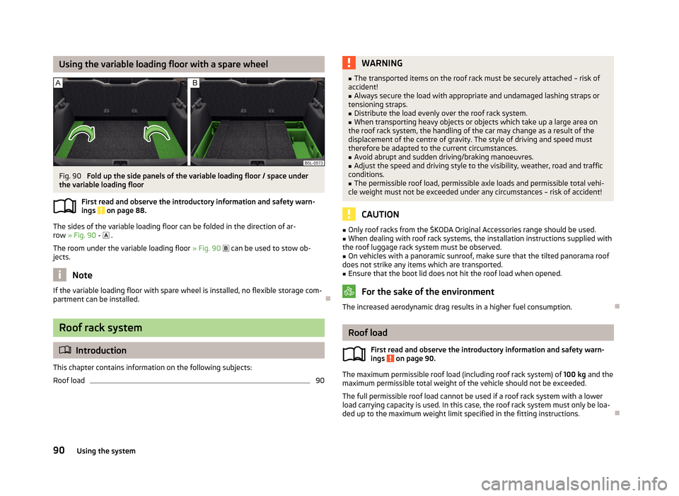
Using the variable loading floor with a spare wheelFig. 90
Fold up the side panels of the variable loading floor / space under
the variable loading floor
First read and observe the introductory information and safety warn-ings
on page 88.
The sides of the variable loading floor can be folded in the direction of ar-row » Fig. 90 -
.
The room under the variable loading floor » Fig. 90
can be used to stow ob-
jects.
Note
If the variable loading floor with spare wheel is installed, no flexible storage com-
partment can be installed.
Roof rack system
Introduction
This chapter contains information on the following subjects:
Roof load
90WARNING■ The transported items on the roof rack must be securely attached – risk of
accident!■
Always secure the load with appropriate and undamaged lashing straps or
tensioning straps.
■
Distribute the load evenly over the roof rack system.
■
When transporting heavy objects or objects which take up a large area on
the roof rack system, the handling of the car may change as a result of the displacement of the centre of gravity. The style of driving and speed musttherefore be adapted to the current circumstances.
■
Avoid abrupt and sudden driving/braking manoeuvres.
■
Adjust the speed and driving style to the visibility, weather, road and traffic
conditions.
■
The permissible roof load, permissible axle loads and permissible total vehi-
cle weight must not be exceeded under any circumstances – risk of accident!
CAUTION
■ Only roof racks from the ŠKODA Original Accessories range should be used.■When dealing with roof rack systems, the installation instructions supplied with
the roof luggage rack system must be observed.■
On vehicles with a panoramic sunroof, make sure that the tilted panorama roof
does not strike any items which are transported.
■
Ensure that the boot lid does not hit the roof load when opened.
For the sake of the environment
The increased aerodynamic drag results in a higher fuel consumption.
Roof load
First read and observe the introductory information and safety warn-
ings
on page 90.
The maximum permissible roof load (including roof rack system) of 100 kg and the
maximum permissible total weight of the vehicle should not be exceeded.
The full permissible roof load cannot be used if a roof rack system with a lower
load carrying capacity is used. In this case, the roof rack system must only be loa-
ded up to the maximum weight limit specified in the fitting instructions.
90Using the system
Page 99 of 266
The interior temperature can be set between +18 °C and +26 ℃. The interior tem-
perature is regulated automatically within this range.
If a temperature lower than +18 °C is selected, a blue symbol lights up at the start
of the numerical scale.
If a temperature higher than +26 °C is selected, a red symbol lights up at the start
of the numerical scale.
At both end positions, Climatronic runs at maximum cooling/heating output and
the temperature is automatically not regulated.
Controlling blower
The Climatronic system controls the blower stages automatically in line with the
interior temperature. However, the blower stages can be manually adapted to
suit your particular needs.
Automatic mode
The automatic mode is used in order to maintain a constant temperature and to
demist the windows in the interior of the car.
If the warning light in the top right corner of the button
lights up, the Clima-
tronic operates in “HIGH”-mode. The “HIGH” mode is the standard setting of the
Climatronic.
Upon pressing the
button again, the Climatronic switches to “LOW”-mode
and the indicator light in the top left corner lights up. The Climatronic uses only in this mode the lower blower speed. However taking into account the noise level,
this is more comfortable, yet be aware that the effectiveness of the air condition-
ing system is reduced particularly if the vehicle is fully occupied.
By pressing the button
again, it is changed to “HIGH”-mode.
Automatic mode is switched off by pressing one of the buttons for the air distri- bution or by increasing/decreasing the blower speed. The temperature is never-
theless regulated.WARNING■ Do not switch off the Climatronic system for longer than necessary.■Switch on the Climatronic system as soon as the windows mist up.Note■Do not stick anything onto or cover the interior temperature sensor B » Fig. 95
as this could impair the functioning of the Climatronic.■
On vehicles equipped with a factory-fitted radio or radio navigation system, the
Climatronic information is also shown on their displays. This function can be
switched off, see » operating instructions for the radio or navigation system .
Note
If the windscreen mists up, press the symbol button . Press the button
once the windscreen has demisted.
Using the air conditioning system economically
First read and observe the introductory information and safety warn-ings
on page 91.
The air conditioning system compressor uses power from the engine when in
cooling mode, which will affect the fuel consumption.
It recommended to open the windows or the doors of a vehicle for which the inte-rior has been strongly heated through the effect of direct sunlight in order to al-
low the heated air to escape.
The cooling system should not be on if the windows are open.
If the desired interior temperature can be achieved without switching the cooling
system on, then we do not recommend turning this on.
For the sake of the environment
Pollutant emissions are also reduced when fuel is saved » page 130, Economical
driving and environmental sustainability .
96Using the system
Page 199 of 266
Inspecting and replenishing
Fuel
Introduction
This chapter contains information on the following subjects:
Refuelling
196
Unleaded petrol
197
Diesel fuel
198
The correct grades of fuel for your vehicle are stated on a sticker affixed to the
inside of the fuel filler flap » Fig. 155 on page 196 -
.
WARNINGThe national legal requirements must be observed if carrying a spare canister
in the vehicle. We do not recommend carrying any fuel canisters in your vehi-
cle for safety reasons. in the event of an accident, these canisters can become
damaged and fuel may escape – risk of fire!
CAUTION
■ Never drive until the fuel tank is completely empty! The irregular supply of fuel
can cause misfiring, which can result in considerable damage to parts of the en-
gine and the exhaust system.■
Immediately remove any fuel that has spilled onto the vehicle's paintwork – risk
of paint damage!
■
If the vehicle was not purchased in the country where it was intended to be op-
erated, you should check whether the fuel specified by the manufacturer is of-
fered in the country where the vehicle will be operated. You should also perhaps
check whether the manufacturer has recommended a different fuel for operation
of the vehicle in the corresponding country. Is this not the case, then you must
check whether it is permitted by the manufacturer to operate the vehicle with an-
other fuel type.
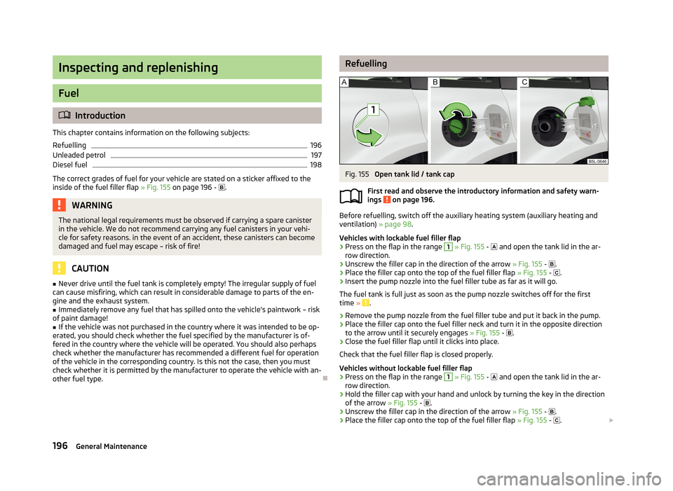
RefuellingFig. 155
Open tank lid / tank cap
First read and observe the introductory information and safety warn-
ings
on page 196.
Before refuelling, switch off the auxiliary heating system (auxiliary heating and ventilation) » page 98.
Vehicles with lockable fuel filler flap
›
Press on the flap in the range
1
» Fig. 155 -
and open the tank lid in the ar-
row direction.
›
Unscrew the filler cap in the direction of the arrow » Fig. 155 -
.
›
Place the filler cap onto the top of the fuel filler flap » Fig. 155 -
.
›
Insert the pump nozzle into the fuel filler tube as far as it will go.
The fuel tank is full just as soon as the pump nozzle switches off for the first time »
.
›
Remove the pump nozzle from the fuel filler tube and put it back in the pump.
›
Place the filler cap onto the fuel filler neck and turn it in the opposite direction
to the arrow until it securely engages » Fig. 155 -
.
›
Close the fuel filler flap until it clicks into place.
Check that the fuel filler flap is closed properly.
Vehicles without lockable fuel filler flap
›
Press on the flap in the range
1
» Fig. 155 -
and open the tank lid in the ar-
row direction.
›
Hold the filler cap with your hand and unlock by turning the key in the direction
of the arrow » Fig. 155 -
.
›
Unscrew the filler cap in the direction of the arrow » Fig. 155 -
.
›
Place the filler cap onto the top of the fuel filler flap
» Fig. 155 -
.
196General Maintenance
Page 200 of 266
›Insert the pump nozzle into the fuel filler tube as far as it will go.
The fuel tank is full just as soon as the pump nozzle switches off for the first time »
.
›
Remove the pump nozzle from the fuel filler tube and put it back in the pump.
›
Screw in the filler cap in the opposite direction of the arrow » Fig. 155 - , until
it audibly clicks into place.
›
Hold the filler cap with one hand, lock it by turning in the opposite direction of the arrow » Fig. 155 - and remove the key.
›
Close the fuel filler flap until it clicks into place.
Check that the fuel filler flap is closed properly.
CAUTION
The fuel tank is full just as soon as the pump nozzle switches off for the first time, provided the nozzle has been operated properly. Do not continue filling the
fuel tank otherwise the expansion volume is filled up.
Note
The fuel capacity for vehicles with front wheel drive is about 55 litres, and for ve-
hicles with four-wheel drive about 60 litres, with about 9 liters as reserve.
Unleaded petrol
First read and observe the introductory information and safety warn-
ings
on page 196.
The vehicle can only be operated with unleaded petrol in compliance with the EN
228 1)
standard.
All petrol engines can be operated using petrol that contains at most 10% bioe-
thanol (E10).
Required fuel - unleaded petrol 95/91 or 92 or 93 RON
Use unleaded fuel with the octane rating 95 RON. Unleaded petrol with the oc-
tane ratings 91, 92 or 93 RON can also be used, but may result in a slight loss in
performance.
Prescribed fuel - unleaded petrol min. 95 RON
Use unleaded fuel with the octane rating 95 RON or higher.
In case of necessity, you can refuel with petrol with the octane ratings 91, 92 or
93 RON, if petrol with the octane rating 95 RON is not available »
.
Prescribed fuel - unleaded fuel 98/95 RON
Use unleaded fuel with the octane rating 98 RON or higher. Unleaded petrol
95 RON can also be used but results in a slight loss in performance.
In case of necessity, you can refuel with petrol with the octane ratings 91, 92 or
93 RON, if unleaded fuel with octane rating 98 RON or 95 RON is not availa-
ble »
.
Fuel additives
Unleaded petrol in accordance with the EN 228 standard 1 )
meets all the condi-
tions for a smooth-running engine. We therefore recommend that no fuel addi-
tives are used. This can result in considerable damage to parts of the engine or
the exhaust system.
CAUTION
■ Even filling the tank with leaded petrol that does not meet the standards once
can lead to serious damage to parts of the exhaust system!■
If a fuel other than unleaded fuel which complies to the above mentioned
standards (e.g. leaded petrol) is used by mistake, do not start the engine or
switch on the ignition! Extensive damage to engine parts can occur! We recom-
mend that you have the fuel system cleaned by a specialist garage.
CAUTION
■ If, in an emergency, the vehicle has to be refuelled with petrol of a lower octane
number than the one prescribed, the journey must only be continued at medium
engine speeds and a low engine load. Driving at high engine revs or a high engine
load can severely damage the engine! Refuel using petrol of the prescribed oc-
tane number as soon as possible.■
Engine parts can be damaged if petrol with a lower octane number than the one
prescribed is used.
■
Even in the event of an emergency, petrol of a lower octane number than 91
RON must not be used, otherwise the engine can be severely damaged!
1)
In Germany also DIN 51626-1 or E10 for unleaded petrol with octane number 91 or 95 or DIN 51626-2
or E5 for unleaded petrol with octane number 95 and 98.
197Inspecting and replenishing
Page 202 of 266
Engine compartment
Introduction
This chapter contains information on the following subjects:
Opening and closing the bonnet
200
Engine compartment overview
201
Radiator fan
201
Windscreen washer system
201WARNINGInjuries or scolding or risks of accident or fire may occur when working in the
engine compartment. For this reason, it is essential to comply with the warn- ing instructions outlined below and with the general applicable safety rules.
The engine compartment of your car is a hazardous area!WARNINGInstructions before beginning work in the engine compartment■Turn off the engine and withdraw the ignition key.■
Firmly apply the handbrake.
■
If the vehicle is fitted with a manual gearbox, move the gearshift lever into
Neutral, or if the vehicle is fitted with an automatic gearbox, move the selec-
tor lever into position P.
■
Allow the engine to cool.
■
Never open the bonnet if you can see steam or coolant escaping from the
engine compartment – risk of scalding! Wait until no more steam or coolant is escaping.
WARNINGInformation for working in the engine room■Keep children clear of the engine compartment.■
Never touch the radiator fan while the engine is still warm. The fan might
suddenly start running!
■
Do not touch any hot engine parts – risk of burns!
■
The coolant is harmful to health.
WARNING (Continued)■ Avoid contact with the coolant.■Coolant vapours are harmful to health.■
Never open the end cover of the coolant expansion reservoir while the en-
gine is still warm. The cooling system is pressurized!
■
When opening the end cover of the coolant expansion reservoir, cover it
with a cloth to protect your face, hands and arms from hot steam or hot cool-
ant.
■
If any coolant splashes into your eyes, immediately rinse out your eyes with
clear water and contact a doctor as soon as possible.
■
Always store the coolant additive securely in its original container, and in
particular out of the reach of children – risk of poisoning!
■
If coolant is swallowed, consult a doctor immediately.
■
Do not leave any items (e.g. cloths or tools) in the engine compartment.
■
Never spill fluids on the hot engine. Such fluids (e.g. the antifreeze con-
tained in the coolant) may ignite!
WARNINGInformation for working in the engine compartment with the engine running■Pay particular attention to rotating engine parts (e.g. V-ribbed belt, genera-
tor, radiator fan) and the high-voltage ignition system – risk to life!■
Never touch the electric wiring on the ignition system.
■
Avoid short circuits in the electrical system - particularly on the vehicle's
battery.
■
Always make sure that no jewellery, loose clothing or long hair can get
caught in rotating engine parts – risk to life! Always remove any jewellery, tie
back long hair and wear tight fitting clothing before completing any work.
WARNINGInformation for working on the fuel system or the electrical system■Always disconnect the vehicle battery from the electrical system.■
Do not smoke.
■
Never work near open flames.
■
Always have a functioning fire extinguisher nearby.
199Inspecting and replenishing
Page 207 of 266
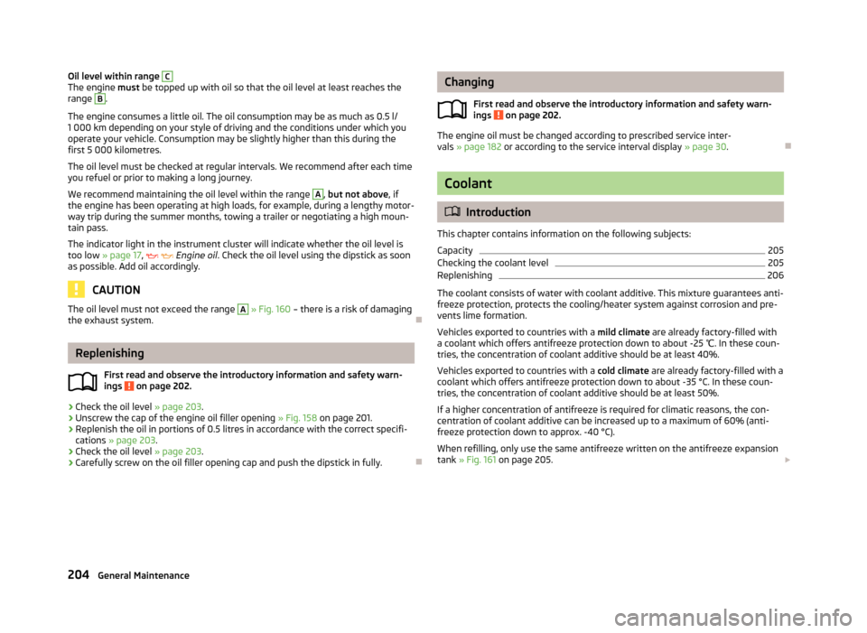
Oil level within range CThe engine must be topped up with oil so that the oil level at least reaches the
range B
.
The engine consumes a little oil. The oil consumption may be as much as 0.5 l/
1 000 km depending on your style of driving and the conditions under which you operate your vehicle. Consumption may be slightly higher than this during thefirst 5 000 kilometres.
The oil level must be checked at regular intervals. We recommend after each time
you refuel or prior to making a long journey.
We recommend maintaining the oil level within the range
A
, but not above , if
the engine has been operating at high loads, for example, during a lengthy motor-
way trip during the summer months, towing a trailer or negotiating a high moun- tain pass.
The indicator light in the instrument cluster will indicate whether the oil level is
too low » page 17 ,
Engine oil . Check the oil level using the dipstick as soon
as possible. Add oil accordingly.
CAUTION
The oil level must not exceed the range A » Fig. 160 – there is a risk of damaging
the exhaust system.
Replenishing
First read and observe the introductory information and safety warn-
ings
on page 202.
›
Check the oil level » page 203.
›
Unscrew the cap of the engine oil filler opening » Fig. 158
on page 201.
›
Replenish the oil in portions of 0.5 litres in accordance with the correct specifi-
cations » page 203 .
›
Check the oil level » page 203.
›
Carefully screw on the oil filler opening cap and push the dipstick in fully.
Changing
First read and observe the introductory information and safety warn-ings
on page 202.
The engine oil must be changed according to prescribed service inter-vals » page 182 or according to the service interval display » page 30.
Coolant
Introduction
This chapter contains information on the following subjects:
Capacity
205
Checking the coolant level
205
Replenishing
206
The coolant consists of water with coolant additive. This mixture guarantees anti- freeze protection, protects the cooling/heater system against corrosion and pre-
vents lime formation.
Vehicles exported to countries with a mild climate are already factory-filled with
a coolant which offers antifreeze protection down to about -25 ℃. In these coun-
tries, the concentration of coolant additive should be at least 40%.
Vehicles exported to countries with a cold climate are already factory-filled with a
coolant which offers antifreeze protection down to about -35 °C. In these coun-
tries, the concentration of coolant additive should be at least 50%.
If a higher concentration of antifreeze is required for climatic reasons, the con-centration of coolant additive can be increased up to a maximum of 60% (anti-
freeze protection down to approx. -40 °C).
When refilling, only use the same antifreeze written on the antifreeze expansion tank » Fig. 161 on page 205.
204General Maintenance
Page 216 of 266
WARNINGInformation on the wheel bolts■The wheel bolts must be clean and must turn easily. Never treat them with
grease or oil.■
The prescribed tightening torque of the wheel bolts for steel and light alloy
wheels is 120 Nm.
■
If the wheel bolts are tightened to a too low tightening torque, the rim can
come loose when the car is moving – risk of accident! A tightening torque
which is too high can damage the bolts and threads and this can result in per-
manent deformation of the contact surfaces on the rim.
■
In case of incorrect treatment of the wheel bolts, the wheel can loosen
when the car is moving – risk of accident!
WARNINGInformation on the spare wheel■Only use the spare wheel while absolutely necessary.■
Never drive with more than one spare wheel mounted.
■
The snow chains cannot be used on the spare wheel.
CAUTION
■ If a spare wheel is used that is not identical to the fitted tyres, the following
must be observed » page 216, Spare wheel .■
Protect the tyres from contact with oil, grease and fuel.
■
Replace lost valve caps.
■
If, in the event of a puncture, it is necessary to fit a spare wheel with a tyre
without a dedicated running direction or with the opposite direction of rotation, drive carefully as the optimal characteristics of the tyre are no longer applicable in
this situation.
For the sake of the environment
Tyres that are insufficiently inflated increase your fuel consumption.
Note
■ We recommend that any work on the wheels or tyres be carried out by a spe-
cialist garage.■
We recommend that you use wheel rims, tyres, full wheel trims and snow chains
from ŠKODA Original Accessories.
Service life of tyresFig. 165
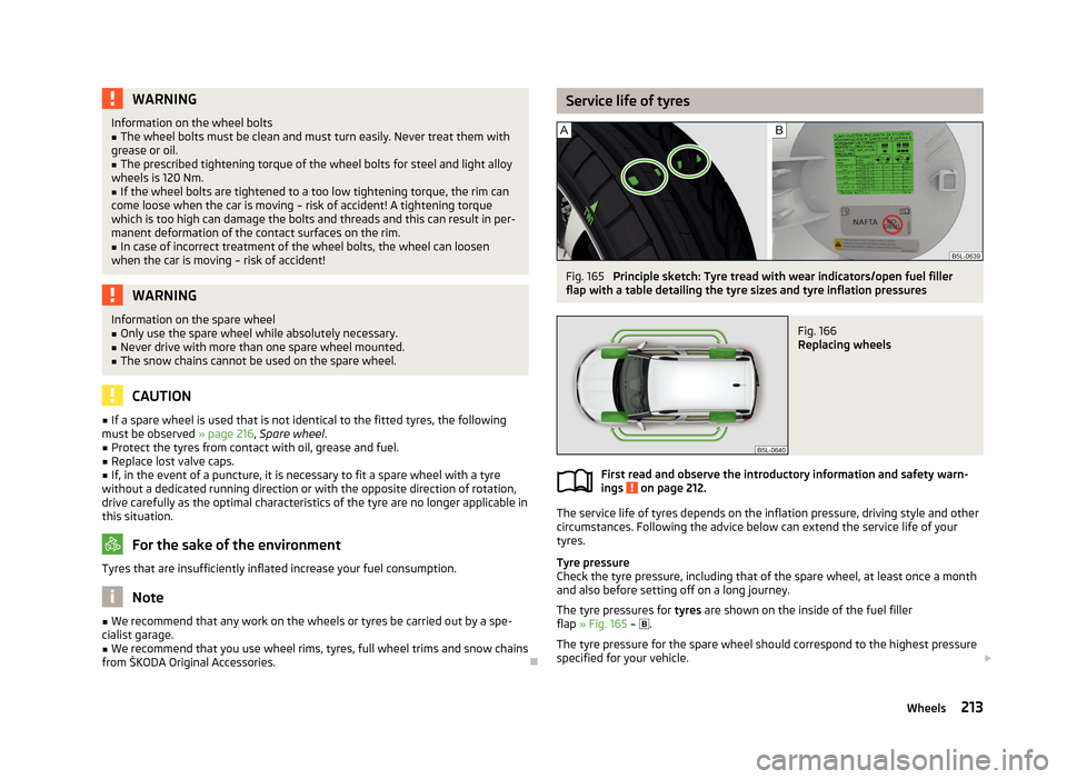
Principle sketch: Tyre tread with wear indicators/open fuel filler
flap with a table detailing the tyre sizes and tyre inflation pressures
Fig. 166
Replacing wheels
First read and observe the introductory information and safety warn-
ings on page 212.
The service life of tyres depends on the inflation pressure, driving style and other
circumstances. Following the advice below can extend the service life of your
tyres.
Tyre pressure
Check the tyre pressure, including that of the spare wheel, at least once a month and also before setting off on a long journey.
The tyre pressures for tyres are shown on the inside of the fuel filler
flap » Fig. 165 –
.
The tyre pressure for the spare wheel should correspond to the highest pressure
specified for your vehicle.
213Wheels
Page 229 of 266
Sealing and inflating the tyreFirst read and observe the introductory information and safety warn-
ings
on page 224.
Sealing
›
Forcefully shake the tyre inflator bottle
10
» Fig. 178 on page 225 several times.
›
Firmly screw the inflation hose
3
onto the tyre inflator bottle
10
in a clockwise
direction. The film on the cap is pierced automatically.
›
Remove the plug from the inflation hose
3
and plug the open end fully onto
the tyre valve.
›
Hold the bottle
10
with the bottom facing upwards and fill all of the sealing
agent from the tyre inflator bottle into the tyre.
›
Remove the empty tyre inflator bottle from the valve.
›
Screw the valve core back into the tyre valve using the valve remover
2
.
Inflating
›
Screw the air compressor tyre inflation hose
7
» Fig. 178 on page 225 firmly on-
to the tyre valve.
›
Start the engine and run it in idle.
›
Plug the connector
6
into 12 Volt socket » page 75.
›
Switch on the air compressor with the ON and OFF switch
9
.
›
Allow the air compressor to run until a pressure of 2.0 - 2.5 bar is achieved. Max-
imum run time of 8 minutes » !
›
Switch off the air compressor.
›
If you cannot reach an air pressure of 2.0 – 2.5 bar, unscrew the tyre inflation
hose
7
from the tyre valve.
›
Drive the vehicle 10 metres forwards or backwards to allow the sealing agent to
“distribute” in the tyre.
›
Firmly screw the tyre inflation hose
7
back onto the tyre valve and repeat the
inflation process.
›
If you cannot reach the required tyre inflation pressure here either, this means
the tyre has sustained too much damage. You cannot seal with tyre with the breakdown kit »
.
›
Switch off the air compressor.
›
Remove the tyre inflation hose
7
from the tyre valve.
Once a tyre inflation pressure of 2.0 – 2.5 bar is achieved, continue the journey at
a maximum speed of 80 km/h (50 mph).
Check the tyre inflation pressure after driving for 10 minutes » page 226, Check
after 10 minutes' driving .
WARNING■
During inflation, the tyre inflation hose and air compressor may get hot –
risk of injury!■
Do not place the hot tyre inflation hose or hot air compressor on flammable
materials – risk of fire!
■
If you cannot inflate the tyre to at least 2.0 bar, this means the damage sus-
tained was too serious. The sealing agent cannot be used to seal the tyre.
Do not drive the vehicle! Seek help from a specialist garage.
CAUTION
Switch off the air compressor after running 8 minutes at the latest – risk of over-
heating! Allow the air compressor to cool a few minutes before switching it on
again.
Check after 10 minutes' driving
First read and observe the introductory information and safety warn-ings
on page 224.
Check the tyre inflation pressure after driving for 10 minutes!
If the tyre inflation pressure is 1.3 bar or less
›
Do not drive the vehicle! You cannot properly seal with tyre with the break-
down kit.
If the tyre inflation pressure is 1.3 bar or more
›
Adjust the tyre inflation pressure to the correct value (see inside of fuel filler cap).
›
Continue driving carefully to the nearest specialist garage at a maximum speed
of 80 km/h (50 mph).
Jump-starting
Introduction
This chapter contains information on the following subjects:
Jump-starting using the battery from another vehicle
227
Jump-starting in vehicles with the START-STOP system
228
226Do-it-yourself