spare wheel SKODA YETI 2013 1.G / 5L Owner's Manual
[x] Cancel search | Manufacturer: SKODA, Model Year: 2013, Model line: YETI, Model: SKODA YETI 2013 1.G / 5LPages: 266, PDF Size: 26.71 MB
Page 91 of 266
Replace batteries » page 232.
Luggage compartment light
If the light is in the holder, it is automatically switched on when the boot lid is
opened.
If the lamp is in the holder, it is automatically switched off when the boot lid is
closed.
CAUTION
■ The removable lamp is not watertight and must therefore be protected against
moisture.■
If the lamp is not switched off and it is correctly inserted in the holder, the bulbs
in the front part
A
» Fig. 86 of the lamp are automatically switched off.
■
If the lamp is not correctly inserted into the holder, it does not light up when
the boot lid is opened and the rechargeable batteries are not charged.
Class N1 vehicles
First read and observe the introductory information and safety warn-
ings
on page 81.
On class N1 vehicles, which are not fitted with a protective grille, a lashing set which complies with the standard EN 12195 (1 - 4) must be used for fastening the
load.
Proper functioning of the electrical installation is essential for safe vehicle opera- tion. It is important to ensure that the electrical installation is not damaged dur-
ing the adjustment process or when the storage area is being loaded and unloa-
ded.
Variable loading floor in the luggage compartment
(Estate)
Introduction
This chapter contains information on the following subjects:
Removing and inserting the variable loading floor
88
Securing the loading floor in the raised position
89Removing and refitting carrier rails89Using the variable loading floor with a spare wheel90
The variable loading floor makes it easier to handle bulky goods and creates an even boot floor when the rear seat backrests are folded forward.
CAUTION
The maximum permissible load of the variable loading floor is 75 kg.
Note
The room under the variable loading floor can be used to stow objects.
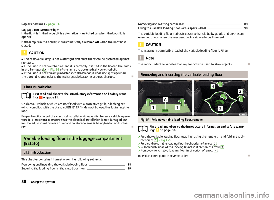
Removing and inserting the variable loading floor
Fig. 87
Fold up variable loading floor/remove
First read and observe the introductory information and safety warn- ings
on page 88.
›
Fold the variable loading floor together using the handle
A
and fold in the di-
rection of
1
» Fig. 87 .
›
Fold up the variable loading floor in direction of arrow
2
.
›
Pull on both sides of the locking levers in direction of arrow
3
.
›
Remove the variable loading floor in direction of arrow
4
.
Insertion takes place in reverse order.
88Using the system
Page 93 of 266
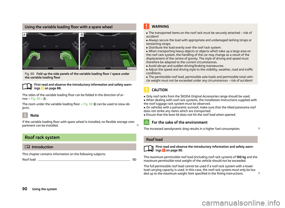
Using the variable loading floor with a spare wheelFig. 90
Fold up the side panels of the variable loading floor / space under
the variable loading floor
First read and observe the introductory information and safety warn-ings
on page 88.
The sides of the variable loading floor can be folded in the direction of ar-row » Fig. 90 -
.
The room under the variable loading floor » Fig. 90
can be used to stow ob-
jects.
Note
If the variable loading floor with spare wheel is installed, no flexible storage com-
partment can be installed.
Roof rack system
Introduction
This chapter contains information on the following subjects:
Roof load
90WARNING■ The transported items on the roof rack must be securely attached – risk of
accident!■
Always secure the load with appropriate and undamaged lashing straps or
tensioning straps.
■
Distribute the load evenly over the roof rack system.
■
When transporting heavy objects or objects which take up a large area on
the roof rack system, the handling of the car may change as a result of the displacement of the centre of gravity. The style of driving and speed musttherefore be adapted to the current circumstances.
■
Avoid abrupt and sudden driving/braking manoeuvres.
■
Adjust the speed and driving style to the visibility, weather, road and traffic
conditions.
■
The permissible roof load, permissible axle loads and permissible total vehi-
cle weight must not be exceeded under any circumstances – risk of accident!
CAUTION
■ Only roof racks from the ŠKODA Original Accessories range should be used.■When dealing with roof rack systems, the installation instructions supplied with
the roof luggage rack system must be observed.■
On vehicles with a panoramic sunroof, make sure that the tilted panorama roof
does not strike any items which are transported.
■
Ensure that the boot lid does not hit the roof load when opened.
For the sake of the environment
The increased aerodynamic drag results in a higher fuel consumption.
Roof load
First read and observe the introductory information and safety warn-
ings
on page 90.
The maximum permissible roof load (including roof rack system) of 100 kg and the
maximum permissible total weight of the vehicle should not be exceeded.
The full permissible roof load cannot be used if a roof rack system with a lower
load carrying capacity is used. In this case, the roof rack system must only be loa-
ded up to the maximum weight limit specified in the fitting instructions.
90Using the system
Page 147 of 266
WARNING■The system does not exempt the driver from his/her responsibility for park-
ing in and manoeuvring out of the parking space.■
External sound sources can have a detrimental effect on parking in and ma-
noeuvring out of the parking space. Under adverse conditions, this can cause
objects or people to not be recognized by the system.
■
When parking in, and manoeuvring out of parking spaces, the system auto-
matically executes quick steering movements. While it is doing so, do not place your hands between the steering wheel – risk of injury!
■
When parking or leaving a parking space on loose or slippery surfaces (grav-
el, snow, ice, etc.) you may stray from the calculated road because of the sur-
face conditions. Therefore we suggest that you do not use the system in such
situations.
CAUTION
■ If other vehicles are parked behind the kerb or on it, the system can also guide
your vehicle beyond the kerb or onto it. Ensure that the wheels or the wheel rims
of your vehicle are not damaged and if necessary intervene in time.■
Under certain circumstances, surfaces or structures of certain objects such as
wire mesh fences or powder snow cannot be recognised by the system.
■
The system function may be limited under adverse weather conditions (heavy
rain, water vapour, very low or high temperatures etc.).
■
The evaluation of the parking space and the parking procedure depends on the
circumference of the wheels on the vehicle. The system only works correctly if
the vehicle is fitted with the wheel size approved by the manufacturer.
■
If wheels other than those approved by the manufacturer are mounted, the re-
sulting position of the vehicle in the parking space can differ slightly. This can be avoided by readjusting the system at a specialist garage.
■
Under certain circumstances, the system may not function correctly, for exam-
ple, if the vehicle is fitted with snow chains or a temporary spare wheel.
Finding a parking spaceFig. 122
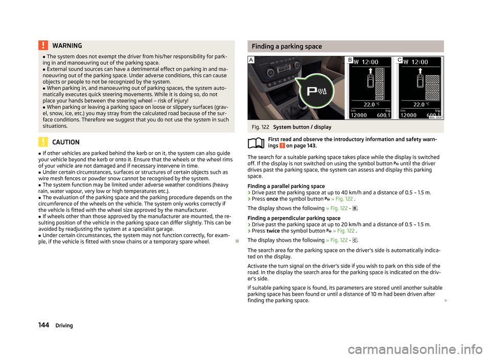
System button / display
First read and observe the introductory information and safety warn-
ings
on page 143.
The search for a suitable parking space takes place while the display is switched
off. If the display is not switched on using the symbol button until the driver
drives past the parking space, the system can assess and display this parking
space.
Finding a parallel parking space
›
Drive past the parking space at up to 40 km/h and a distance of 0.5 – 1.5 m.
›
Press once the symbol button
» Fig. 122 .
The display shows the following » Fig. 122 -
.
Finding a perpendicular parking space
›
Drive past the parking space at up to 20 km/h and a distance of 0.5 – 1.5 m.
›
Press twice the symbol button
» Fig. 122 .
The display shows the following » Fig. 122 -
.
The search area for the parking space on the driver's side is automatically indica-
ted on the display.
Activate the turn signal on the driver's side if you wish to park on this side of the
road. In the display the search area for the parking space is indicated on the driv-
er's side.
If suitable parking space is found, its parameters are stored until another suitable
parking space has been found or until a distance of 10 m had been driven after
finding the parking space.
144Driving
Page 156 of 266
Green box on the tow bar
Tow ball
The tow bar can be removed and is kept in the spare wheel compartment or in a
compartment for the spare wheel in the boot » page 220, Vehicle tool kit .
Note
On the bottom of the key is a code number. If you lose a key, please contact a
specialist garage, who will be able to use this code number to provide you with a new one.
Setting the ready position
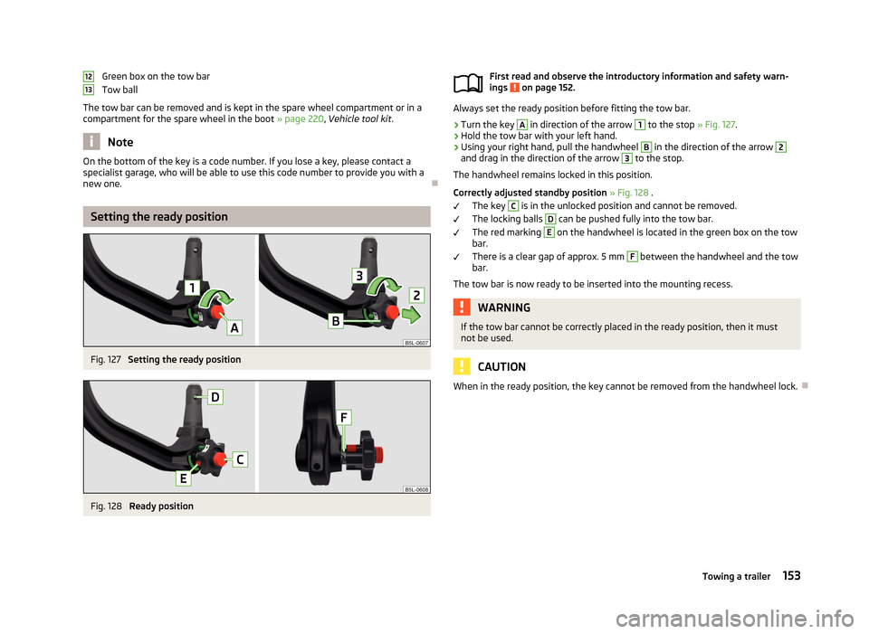
Fig. 127
Setting the ready position
Fig. 128
Ready position
1213First read and observe the introductory information and safety warn-
ings on page 152.
Always set the ready position before fitting the tow bar.
›
Turn the key
A
in direction of the arrow
1
to the stop » Fig. 127.
›
Hold the tow bar with your left hand.
›
Using your right hand, pull the handwheel
B
in the direction of the arrow
2
and drag in the direction of the arrow
3
to the stop.
The handwheel remains locked in this position.
Correctly adjusted standby position » Fig. 128 .
The key
C
is in the unlocked position and cannot be removed.
The locking balls
D
can be pushed fully into the tow bar.
The red marking
E
on the handwheel is located in the green box on the tow
bar.
There is a clear gap of approx. 5 mm
F
between the handwheel and the tow
bar.
The tow bar is now ready to be inserted into the mounting recess.
WARNINGIf the tow bar cannot be correctly placed in the ready position, then it must
not be used.
CAUTION
When in the ready position, the key cannot be removed from the handwheel lock.
153Towing a trailer
Page 215 of 266

Wheels
Tyres and wheel rims
Introduction
This chapter contains information on the following subjects:
Service life of tyres
213
New tyres
214
Unidirectional tyres
215
Tyre pressure monitor
215
Spare wheel
216
Full wheel trim
217
Wheel bolts
217
Wheel bolts
217WARNINGThe national legal regulations must be observed for the use of tyres.WARNINGInstructions for the use of tyres■For the first 500 km, new tyres do not yet provide optimum grip, and appro-
priate care should therefore be taken when driving – risk of accident!■
Only use radial tyres of the same type, size (rolling circumference) and tread
pattern on all four wheels.
■
For reasons of driving safety, do not replace tyres individually.
■
Never exceed the maximum permissible load bearing capacity for fitted
tyres – risk of accident!
■
Never exceed the maximum permissible speed for fitted tyres – risk of acci-
dent!
■
Incorrect wheel alignment at the front or rear impairs handling – risk of acci-
dent!
WARNING (Continued)■ Unusual vibrations or pulling of the vehicle to one side could be a sign of
tyre damage. If there is any doubt that a wheel is damaged, immediately re-
duce your speed and stop! If no external damage is evident, drive slowly and
carefully to the nearest specialist garage to have the vehicle checked.■
Only use tyres or wheel rims that have been approved by ŠKODA for your
model of vehicle. Failure to observe this instruction may impair the road safety
of your vehicle – risk of accident!
WARNINGInformation regarding tyre damage or wear■Never use tyres if you do not know anything about the condition and age.■
Never drive with damaged tyres – risk of accident!
■
Immediately replace damaged wheel rims or tyres.
■
You must have your tyres replaced with new ones at the latest when the
wear indicators have been worn down.
■
Worn tyres impair necessary adhesion to the road surface, particularly at
high speeds on wet roads. This could lead to “aquaplaning” (uncontrolled ve- hicle movement – “swimming” on a wet road surface).
WARNINGInformation on tyre pressure■The tyre control display does not absolve the driver of the responsibility to
ensure the correct tyre inflation pressure. Check the tyre inflation pressure at
regular intervals.■
Insufficient or excessive inflation pressure impairs handling – risk of acci-
dent!
■
If the inflation pressure is too low, the tyre will have to overcome a higher
rolling resistance. This will cause a significant increase in the temperature of
the tyre, especially at higher speeds. This can result in tread separation and a
tyre blowout.
212General Maintenance
Page 216 of 266
WARNINGInformation on the wheel bolts■The wheel bolts must be clean and must turn easily. Never treat them with
grease or oil.■
The prescribed tightening torque of the wheel bolts for steel and light alloy
wheels is 120 Nm.
■
If the wheel bolts are tightened to a too low tightening torque, the rim can
come loose when the car is moving – risk of accident! A tightening torque
which is too high can damage the bolts and threads and this can result in per-
manent deformation of the contact surfaces on the rim.
■
In case of incorrect treatment of the wheel bolts, the wheel can loosen
when the car is moving – risk of accident!
WARNINGInformation on the spare wheel■Only use the spare wheel while absolutely necessary.■
Never drive with more than one spare wheel mounted.
■
The snow chains cannot be used on the spare wheel.
CAUTION
■ If a spare wheel is used that is not identical to the fitted tyres, the following
must be observed » page 216, Spare wheel .■
Protect the tyres from contact with oil, grease and fuel.
■
Replace lost valve caps.
■
If, in the event of a puncture, it is necessary to fit a spare wheel with a tyre
without a dedicated running direction or with the opposite direction of rotation, drive carefully as the optimal characteristics of the tyre are no longer applicable in
this situation.
For the sake of the environment
Tyres that are insufficiently inflated increase your fuel consumption.
Note
■ We recommend that any work on the wheels or tyres be carried out by a spe-
cialist garage.■
We recommend that you use wheel rims, tyres, full wheel trims and snow chains
from ŠKODA Original Accessories.
Service life of tyresFig. 165
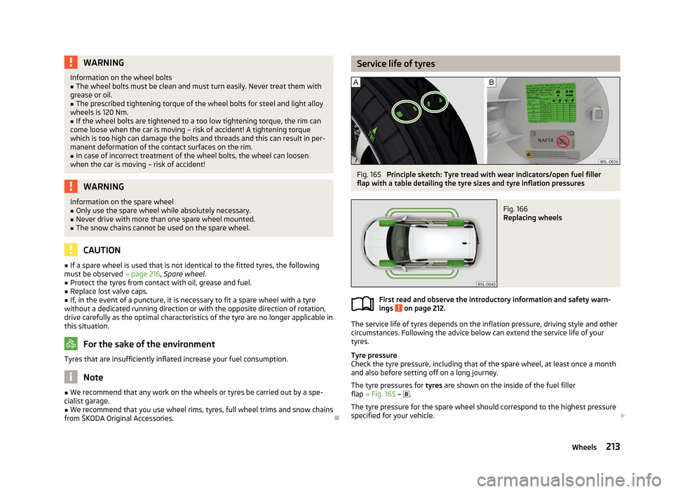
Principle sketch: Tyre tread with wear indicators/open fuel filler
flap with a table detailing the tyre sizes and tyre inflation pressures
Fig. 166
Replacing wheels
First read and observe the introductory information and safety warn-
ings on page 212.
The service life of tyres depends on the inflation pressure, driving style and other
circumstances. Following the advice below can extend the service life of your
tyres.
Tyre pressure
Check the tyre pressure, including that of the spare wheel, at least once a month and also before setting off on a long journey.
The tyre pressures for tyres are shown on the inside of the fuel filler
flap » Fig. 165 –
.
The tyre pressure for the spare wheel should correspond to the highest pressure
specified for your vehicle.
213Wheels
Page 218 of 266
650 kg
670 kg
690 kg
730 kg
775 kg
Speed symbol
This indicates the maximum permissible vehicle speed with fitted tyres in each
category.
160 km/h
170 km/h
180 km/h
190 km/h
200 km/h
210 km/h
240 km/h
270 km/h
CAUTION
The information about the load index and the speed symbol is listed in your vehi-
cle documents.
Unidirectional tyres
First read and observe the introductory information and safety warn-
ings
on page 212.
The direction of rotation of the tyres is marked by arrows on the wall of the tyre.
The indicated direction of rotation must be adhered to in order to ensure the op- timal characteristics of these tyres.
These characteristics mainly relate to the following: › Increased driving stability.
› Reduced risk of aquaplaning.
› Reduced tyre noise and tyre wear.
9394959799QRSTUHVWTyre pressure monitorFig. 167
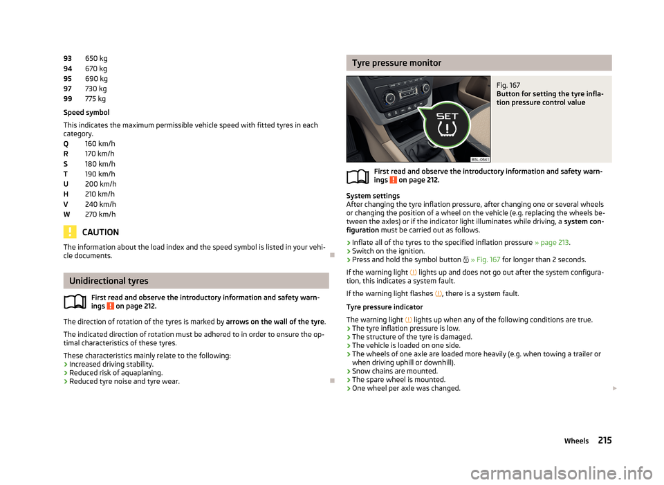
Button for setting the tyre infla-
tion pressure control value
First read and observe the introductory information and safety warn-
ings on page 212.
System settings
After changing the tyre inflation pressure, after changing one or several wheels
or changing the position of a wheel on the vehicle (e.g. replacing the wheels be-
tween the axles) or if the indicator light illuminates while driving, a system con-
figuration must be carried out as follows.
›
Inflate all of the tyres to the specified inflation pressure » page 213.
›
Switch on the ignition.
›
Press and hold the symbol button
» Fig. 167 for longer than 2 seconds.
If the warning light
lights up and does not go out after the system configura-
tion, this indicates a system fault.
If the warning light flashes
, there is a system fault.
Tyre pressure indicator
The warning light
lights up when any of the following conditions are true.
› The tyre inflation pressure is low.
› The structure of the tyre is damaged.
› The vehicle is loaded on one side.
› The wheels of one axle are loaded more heavily (e.g. when towing a trailer or
when driving uphill or downhill).
› Snow chains are mounted.
› The spare wheel is mounted.
› One wheel per axle was changed.
215Wheels
Page 219 of 266
WARNING■When the warning light illuminates, immediately reduce the speed and
avoid sudden steering and brake manoeuvres. Stop the vehicle as soon as
possible and inspect the tyres and their inflation pressure.■
Under certain circumstances (e.g. sporty style of driving, wintry or unpaved
roads) the warning light can be delayed or does not light up at all.
CAUTION
■
The tyre control display does therefore not replace the regular tyre inflation
pressure control, as the system cannot detect an even loss of pressure.■
The system cannot warn in case of very rapid tyre inflation pressure loss, e.g. in
case of sudden tyre damage. In this case carefully bring the vehicle to a standstill
without sudden steering movements or sharp braking.
■
To ensure a proper functioning of the tyre control display, it is necessary to re-
peat the basic setting every 10000 km or once a year.
Spare wheel
Fig. 168
Boot: Spare wheel
First read and observe the introductory information and safety warn-
ings on page 212.
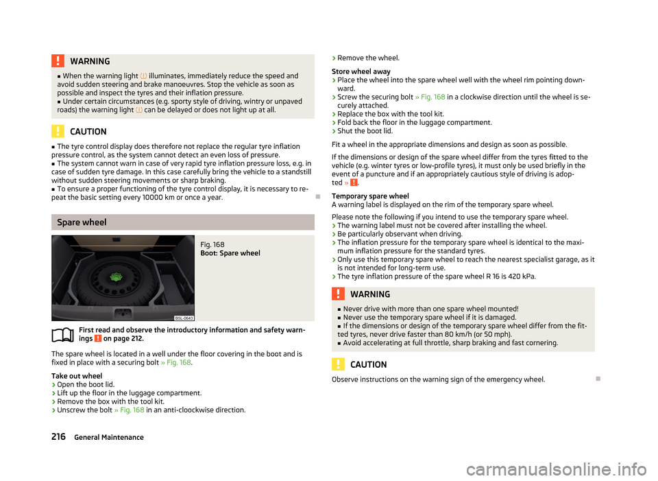
The spare wheel is located in a well under the floor covering in the boot and is
fixed in place with a securing bolt » Fig. 168.
Take out wheel
›
Open the boot lid.
›
Lift up the floor in the luggage compartment.
›
Remove the box with the tool kit.
›
Unscrew the bolt » Fig. 168 in an anti-cloockwise direction.
›Remove the wheel.
Store wheel away›
Place the wheel into the spare wheel well with the wheel rim pointing down- ward.
›
Screw the securing bolt » Fig. 168 in a clockwise direction until the wheel is se-
curely attached.
›
Replace the box with the tool kit.
›
Fold back the floor in the luggage compartment.
›
Shut the boot lid.
Fit a wheel in the appropriate dimensions and design as soon as possible.
If the dimensions or design of the spare wheel differ from the tyres fitted to the
vehicle (e.g. winter tyres or low-profile tyres), it must only be used briefly in the
event of a puncture and if an appropriately cautious style of driving is adop-
ted »
.
Temporary spare wheel
A warning label is displayed on the rim of the temporary spare wheel.
Please note the following if you intend to use the temporary spare wheel. › The warning label must not be covered after installing the wheel.
› Be particularly observant when driving.
› The inflation pressure for the temporary spare wheel is identical to the maxi-
mum inflation pressure for the standard tyres.
› Only use this temporary spare wheel to reach the nearest specialist garage, as it
is not intended for long-term use.
› The tyre inflation pressure of the spare wheel R 16 is 420 kPa.
WARNING■
Never drive with more than one spare wheel mounted!■Never use the temporary spare wheel if it is damaged.■
If the dimensions or design of the temporary spare wheel differ from the fit-
ted tyres, never drive faster than 80 km/h (or 50 mph).
■
Avoid accelerating at full throttle, sharp braking and fast cornering.
CAUTION
Observe instructions on the warning sign of the emergency wheel.
216General Maintenance
Page 220 of 266
Full wheel trimFirst read and observe the introductory information and safety warn-
ings
on page 212.
Extracting
›
Hook the clamp found in the vehicle tool kit » page 220 into the reinforced edge
of the wheel trim.
›
Push the wheel wrench through the clamp, support on the tyre and pull off the
wheel trim.
Install
›
Press the wheel trim onto the wheel rim at the designated valve opening.
›
Then press the trim into the wheel rim until its entire circumference locks cor- rectly in place.
CAUTION
■ Use the pressure of your hand only, do not strike the full wheel trim. Avoid
heavy impacts when the trim has not yet been inserted into the wheel rim. This
could cause damage to the guide and centring elements of the trim.■
When using the anti-theft wheel bolt, ensure that it is in the hole in the valve
area » page 224 , Securing wheels against theft .
■
If wheel trims are retrofitted it must be ensured that an adequate flow of air is
assured to cool the brake system.
Wheel bolts
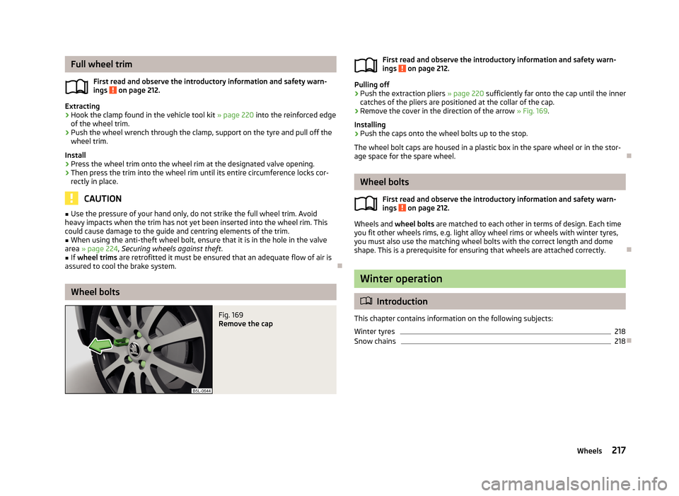
Fig. 169
Remove the capFirst read and observe the introductory information and safety warn-
ings on page 212.
Pulling off
›
Push the extraction pliers » page 220 sufficiently far onto the cap until the inner
catches of the pliers are positioned at the collar of the cap.
›
Remove the cover in the direction of the arrow » Fig. 169.
Installing
›
Push the caps onto the wheel bolts up to the stop.
The wheel bolt caps are housed in a plastic box in the spare wheel or in the stor-
age space for the spare wheel.
Wheel bolts
First read and observe the introductory information and safety warn-ings
on page 212.
Wheels and wheel bolts are matched to each other in terms of design. Each time
you fit other wheels rims, e.g. light alloy wheel rims or wheels with winter tyres,
you must also use the matching wheel bolts with the correct length and dome
shape. This is a prerequisite for ensuring that wheels are attached correctly.
Winter operation
Introduction
This chapter contains information on the following subjects:
Winter tyres
218
Snow chains
218
217Wheels
Page 222 of 266
Do-it-yourself
Emergency equipment and self-help
Emergency equipment
Introduction
This chapter contains information on the following subjects:
First aid kit and warning triangle
219
reflective vest
219
Fire extinguisher
220
Vehicle tool kit
220
First aid kit and warning triangle
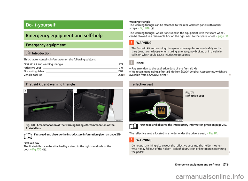
Fig. 170
Accommodation of the warning triangle/accommodation of the
first-aid box
First read and observe the introductory information given on page 219.
First-aid box
The first-aid box can be attached by a strap to the right-hand side of the
boot » Fig. 170 -
.
Warning triangle
The warning triangle can be attached to the rear wall trim panel with rubber
straps » Fig. 170 - .
The warning triangle, which is included in the equipment with the spare wheel,
can be stowed in a removable box on the right next to the spare wheel » page 88.WARNINGThe first-aid kit and warning triangle must always be secured safely so that
they do not come loose when making an emergency braking or in a vehicle
collision which could cause injuries to occupants.
Note
■ Pay attention to the expiration date of the first-aid kit.■We recommend using a first-aid kit from ŠKODA Original Accessories, which are
available from a ŠKODA Partner.
reflective vest
Fig. 171
Reflective vest
First read and observe the introductory information given on page 219.
The reflective vest is located in a holder under the driver's seat, » Fig. 171.
WARNINGDo not put anything else except the reflective vest into the holder – other-
wise it may fall out of the holder – risk of obstruction or limitation in operating
the pedal! 219Emergency equipment and self-help