weight SKODA YETI 2013 1.G / 5L Owner's Manual
[x] Cancel search | Manufacturer: SKODA, Model Year: 2013, Model line: YETI, Model: SKODA YETI 2013 1.G / 5LPages: 266, PDF Size: 26.71 MB
Page 80 of 266
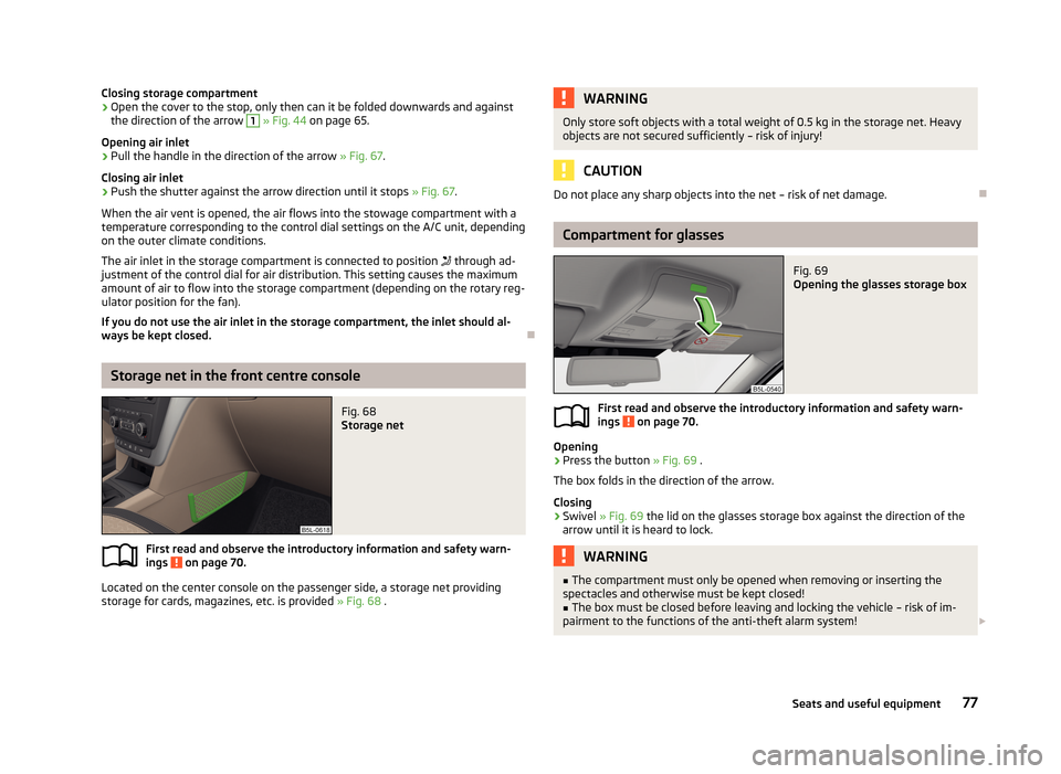
Closing storage compartment›Open the cover to the stop, only then can it be folded downwards and againstthe direction of the arrow 1
» Fig. 44 on page 65.
Opening air inlet
›
Pull the handle in the direction of the arrow » Fig. 67.
Closing air inlet
›
Push the shutter against the arrow direction until it stops » Fig. 67.
When the air vent is opened, the air flows into the stowage compartment with a
temperature corresponding to the control dial settings on the A/C unit, depending on the outer climate conditions.
The air inlet in the storage compartment is connected to position
through ad-
justment of the control dial for air distribution. This setting causes the maximum
amount of air to flow into the storage compartment (depending on the rotary reg-
ulator position for the fan).
If you do not use the air inlet in the storage compartment, the inlet should al-
ways be kept closed.
Storage net in the front centre console
Fig. 68
Storage net
First read and observe the introductory information and safety warn-
ings on page 70.
Located on the center console on the passenger side, a storage net providing storage for cards, magazines, etc. is provided » Fig. 68 .
WARNINGOnly store soft objects with a total weight of 0.5 kg in the storage net. Heavy
objects are not secured sufficiently – risk of injury!
CAUTION
Do not place any sharp objects into the net – risk of net damage.
Compartment for glasses
Fig. 69
Opening the glasses storage box
First read and observe the introductory information and safety warn-
ings on page 70.
Opening
›
Press the button » Fig. 69 .
The box folds in the direction of the arrow.
Closing
›
Swivel » Fig. 69 the lid on the glasses storage box against the direction of the
arrow until it is heard to lock.
WARNING■ The compartment must only be opened when removing or inserting the
spectacles and otherwise must be kept closed!■
The box must be closed before leaving and locking the vehicle – risk of im-
pairment to the functions of the anti-theft alarm system! 77Seats and useful equipment
Page 81 of 266
CAUTIONDo not put any heat-sensitive objects in the glasses storage box - they may be
damaged.
Storage compartment on the passenger side
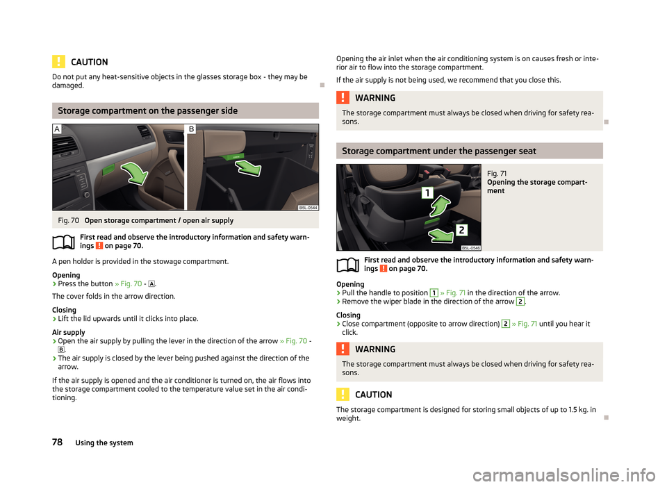
Fig. 70
Open storage compartment / open air supply
First read and observe the introductory information and safety warn-
ings
on page 70.
A pen holder is provided in the stowage compartment.
Opening
›
Press the button » Fig. 70 -
.
The cover folds in the arrow direction.
Closing
›
Lift the lid upwards until it clicks into place.
Air supply
›
Open the air supply by pulling the lever in the direction of the arrow » Fig. 70 -
.
›
The air supply is closed by the lever being pushed against the direction of the
arrow.
If the air supply is opened and the air conditioner is turned on, the air flows into
the storage compartment cooled to the temperature value set in the air condi-
tioning.
Opening the air inlet when the air conditioning system is on causes fresh or inte-
rior air to flow into the storage compartment.
If the air supply is not being used, we recommend that you close this.WARNINGThe storage compartment must always be closed when driving for safety rea- sons.
Storage compartment under the passenger seat
Fig. 71
Opening the storage compart-
ment
First read and observe the introductory information and safety warn- ings on page 70.
Opening
›
Pull the handle to position
1
» Fig. 71 in the direction of the arrow.
›
Remove the wiper blade in the direction of the arrow
2
.
Closing
›
Close compartment (opposite to arrow direction)
2
» Fig. 71 until you hear it
click.
WARNINGThe storage compartment must always be closed when driving for safety rea-
sons.
CAUTION
The storage compartment is designed for storing small objects of up to 1.5 kg. in weight.
78Using the system
Page 83 of 266
CAUTIONBefore folding forward, the rear center seat storage compartment must be closed- there is a risk of damage to the storage compartment.
Folding table on front seat backrest
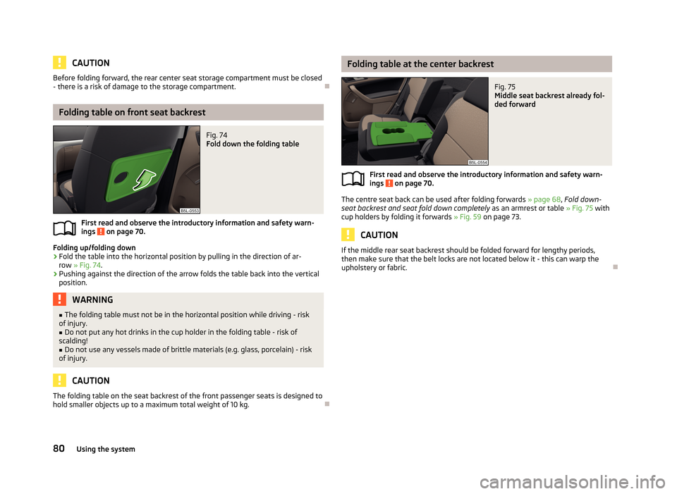
Fig. 74
Fold down the folding table
First read and observe the introductory information and safety warn-
ings on page 70.
Folding up/folding down
›
Fold the table into the horizontal position by pulling in the direction of ar- row » Fig. 74 .
›
Pushing against the direction of the arrow folds the table back into the vertical
position.
WARNING■ The folding table must not be in the horizontal position while driving - risk
of injury.■
Do not put any hot drinks in the cup holder in the folding table - risk of
scalding!
■
Do not use any vessels made of brittle materials (e.g. glass, porcelain) - risk
of injury.
CAUTION
The folding table on the seat backrest of the front passenger seats is designed to
hold smaller objects up to a maximum total weight of 10 kg.
Folding table at the center backrestFig. 75
Middle seat backrest already fol-
ded forward
First read and observe the introductory information and safety warn-
ings on page 70.
The centre seat back can be used after folding forwards » page 68, Fold down-
seat backrest and seat fold down completely as an armrest or table » Fig. 75 with
cup holders by folding it forwards » Fig. 59 on page 73.
CAUTION
If the middle rear seat backrest should be folded forward for lengthy periods,
then make sure that the belt locks are not located below it - this can warp the
upholstery or fabric.
80Using the system
Page 84 of 266
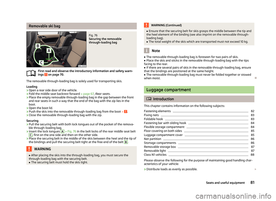
Removable ski bagFig. 76
Securing the removable
through-loading bag
First read and observe the introductory information and safety warn-
ings on page 70.
The removable through-loading bag is solely used for transporting skis.
Loading
›
Open a rear side door of the vehicle.
›
Fold the middle seat backrest forward » page 67, Rear seats .
›
Place the empty removable through-loading bag in the gap between the front
and rear seats in such a way that the end of the bag with the zip lies in the
boot.
›
Open the boot lid.
›
Push the skis into the removable through-loading bag from the boot » .
›
Close the removable through-loading bag with the zip.
Securing
›
Pull the securing belt with both lock tongues out of the pocket of the remova- ble through-loading bag.
›
Insert the lock tongues
A
» Fig. 76 in the belt locks of the rear middle seat belt
C
, first on the one side and then on the other side.
›
Place the securing belt in the middle of the skis between the heel and the tip of
the bindings and pull the securing belt tight at the free end of the belt
B
.
WARNING■ After placing the skis into the through-loading bag, you must secure the
through-loading bag with the securing belt.■
The securing belt must hold the skis tight.WARNING (Continued)■ Ensure that the securing belt for skis grasps the middle between the tip and
the heel element of the binding (see also imprint on the removable through-
loading bag).■
The total weight of the skis which are transported must not exceed 10 kg.
Note
■ The removable through-loading bag is foreseen for two pairs of skis.■Place the skis and sticks in the removable through-loading bag with the tips
facing to the rear.■
If there are several pairs of skis in the removable through-loading bag, ensure
that the bindings are positioned at the same height.
■
The removable through-loading bag must never be folded together or stowed
when moist.
Luggage compartment
Introduction
This chapter contains information on the following subjects:
Fastening elements
82
Fixing nets
83
Foldable hook
83
Fastening bar with sliding hook
84
Flexible storage compartment
84
Floor covering on both sides
85
Luggage compartment cover
85
Net partition
86
Stortage compartments
86
Removable storage box
87
Removable light
87
Class N1 vehicles
88
Please observe the following for the purpose of maintaining good handling char-
acteristics of your vehicle:
›
Distribute loads as evenly as possible.
81Seats and useful equipment
Page 85 of 266
›Place heavy objects as far forward as possible.›Attach the items of luggage to the lashing eyes or using the nets
» page 82.
In the event of an accident, even small and light objects gain so much kinetic en-
ergy that they can cause severe injuries.
The magnitude of the kinetic energy is dependent on the speed at which the ve-
hicle is travelling and the weight of the object.
Example: In the event of a frontal collision at a speed of 50 km/h, an object with a
weight of 4.5 kg produces an energy, which corresponds to 20 times its own
weight. This means that it results in a weight of approx. 90 kg “ ”.WARNING■ Store the objects in the boot and attach them to the lashing eyes.■Loose objects can be thrown forward during a sudden manoeuvre or in case
of an accident and can injure the occupants or other road users.■
Loose objects could hit a deployed airbag and injure occupants – danger of
death!
■
Please note that transporting heavy objects alters the handling properties
of the vehicle due to the displacement of the centre of gravity – risk of acci-
dent! The speed and style of driving must be adjusted accordingly.
■
If the items of luggage or objects are attached to the lashing eyes with un-
suitable or damaged lashing straps, injuries can occur in the event of braking manoeuvres or accidents. To prevent items of luggage from moving around,
always use suitable lashing straps which must be firmly attached to the lash-
ing eyes.
■
The transported items must be stowed in such a way that no objects are
able to slip forward on sudden driving or braking manoeuvres – risk of injury!
■
When transporting objects in the luggage compartment that has been en-
larged by folding the rear seats forward, ensure the safety of the passengers transported on the other rear seats » page 162, Correct seated position for
the passengers in the rear seats .
■
If the rear seat next to the folded forward seat is occupied, ensure maxi-
mum safety, e.g. by placing the goods to be transported in such a way that the
seat is prevented from folding back in case of a rear collision.
■
Do not drive with the luggage compartment lid fully opened or slightly ajar
otherwise exhaust gases may get into the interior of the vehicle – risk of poi-
soning!
■
Do not exceed the permissible axle loads and permissible gross weight of
the vehicle – risk of accident!
■
Do not transport people in the boot!
CAUTIONPlease ensure that the heating elements for the rear window heater are not dam-
aged as a result of abrasive objects.
Note
Tyre pressure must be adjusted to the load » page 213, Service life of tyres .
Fastening elements
Fig. 77
Fasteners: Version 1/version 2
First read and observe the introductory information and safety warn- ings
on page 81.
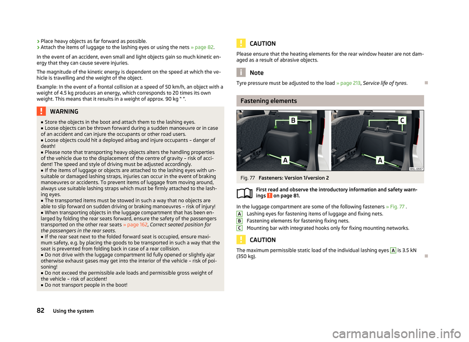
In the luggage compartment are some of the following fasteners » Fig. 77 .
Lashing eyes for fastening items of luggage and fixing nets.
Fastening elements for fastening fixing nets.
Mounting bar with integrated hooks only for fixing mounting networks.
CAUTION
The maximum permissible static load of the individual lashing eyes A is 3.5 kN
(350 kg).
ABC82Using the system
Page 87 of 266
Fastening bar with sliding hookFig. 80
Sliding hook on the mounting bar / removing hook
First read and observe the introductory information and safety warn-
ings
on page 81.
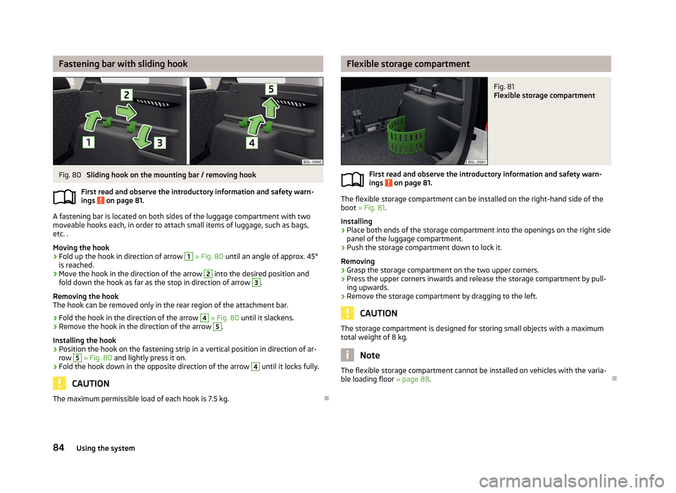
A fastening bar is located on both sides of the luggage compartment with two
moveable hooks each, in order to attach small items of luggage, such as bags,
etc. .
Moving the hook
›
Fold up the hook in direction of arrow
1
» Fig. 80 until an angle of approx. 45°
is reached.
›
Move the hook in the direction of the arrow
2
into the desired position and
fold down the hook as far as the stop in direction of arrow
3
.
Removing the hook
The hook can be removed only in the rear region of the attachment bar.
›
Fold the hook in the direction of the arrow
4
» Fig. 80 until it slackens.
›
Remove the hook in the direction of the arrow
5
.
Installing the hook
›
Position the hook on the fastening strip in a vertical position in direction of ar- row
5
» Fig. 80 and lightly press it on.
›
Fold the hook down in the opposite direction of the arrow
4
until it locks fully.
CAUTION
The maximum permissible load of each hook is 7.5 kg.
Flexible storage compartmentFig. 81
Flexible storage compartment
First read and observe the introductory information and safety warn-
ings on page 81.
The flexible storage compartment can be installed on the right-hand side of the
boot » Fig. 81 .
Installing
›
Place both ends of the storage compartment into the openings on the right side
panel of the luggage compartment.
›
Push the storage compartment down to lock it.
Removing
›
Grasp the storage compartment on the two upper corners.
›
Press the upper corners inwards and release the storage compartment by pull-
ing upwards.
›
Remove the storage compartment by dragging to the left.
CAUTION
The storage compartment is designed for storing small objects with a maximum
total weight of 8 kg.
Note
The flexible storage compartment cannot be installed on vehicles with the varia-
ble loading floor » page 88.
84Using the system
Page 90 of 266
CAUTION■The removable storage compartment A » Fig. 84 on the left side is suitable for
stowing small objects weighing up to 1.5 kg.■
The storage compartment
B
is designed for storing small objects of up to 0.5
kg. in weight in total.
Removable storage box
Fig. 85
Storage box
First read and observe the introductory information and safety warn-
ings on page 81.
The storage box » Fig. 85 is placed under the variable loading floor and can be
taken out.
There is a storage space for the vehicle tool kit under the storage box » page 220 , Vehicle tool kit .
WARNINGThe removable storage box must be located under the variable loading floor
for the safe use of the variable loading floor.
Removable lightFig. 86
Use light / remove light
First read and observe the introductory information and safety warn-
ings
on page 81.
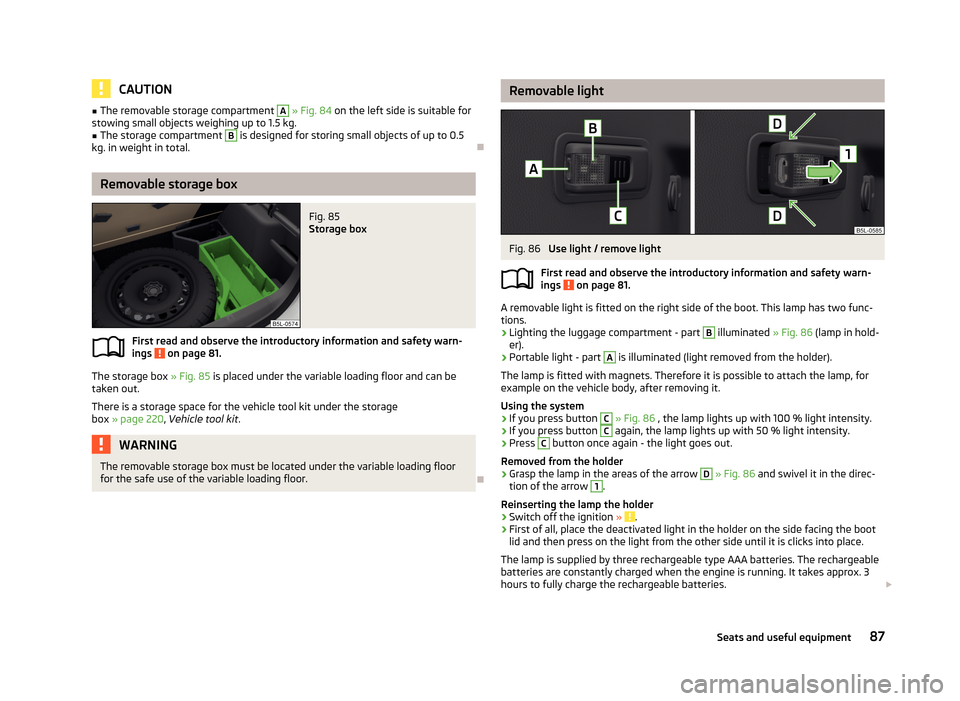
A removable light is fitted on the right side of the boot. This lamp has two func-
tions.
› Lighting the luggage compartment - part
B
illuminated
» Fig. 86 (lamp in hold-
er).
› Portable light - part
A
is illuminated (light removed from the holder).
The lamp is fitted with magnets. Therefore it is possible to attach the lamp, for
example on the vehicle body, after removing it.
Using the system
› If you press button
C
» Fig. 86 , the lamp lights up with 100 % light intensity.
› If you press button
C
again, the lamp lights up with 50 % light intensity.
› Press
C
button once again - the light goes out.
Removed from the holder
› Grasp the lamp in the areas of the arrow
D
» Fig. 86 and swivel it in the direc-
tion of the arrow
1
.
Reinserting the lamp the holder › Switch off the ignition
»
.
› First of all, place the deactivated light in the holder on the side facing the boot
lid and then press on the light from the other side until it is clicks into place.
The lamp is supplied by three rechargeable type AAA batteries. The rechargeable
batteries are constantly charged when the engine is running. It takes approx. 3
hours to fully charge the rechargeable batteries.
87Seats and useful equipment
Page 93 of 266
Using the variable loading floor with a spare wheelFig. 90
Fold up the side panels of the variable loading floor / space under
the variable loading floor
First read and observe the introductory information and safety warn-ings
on page 88.
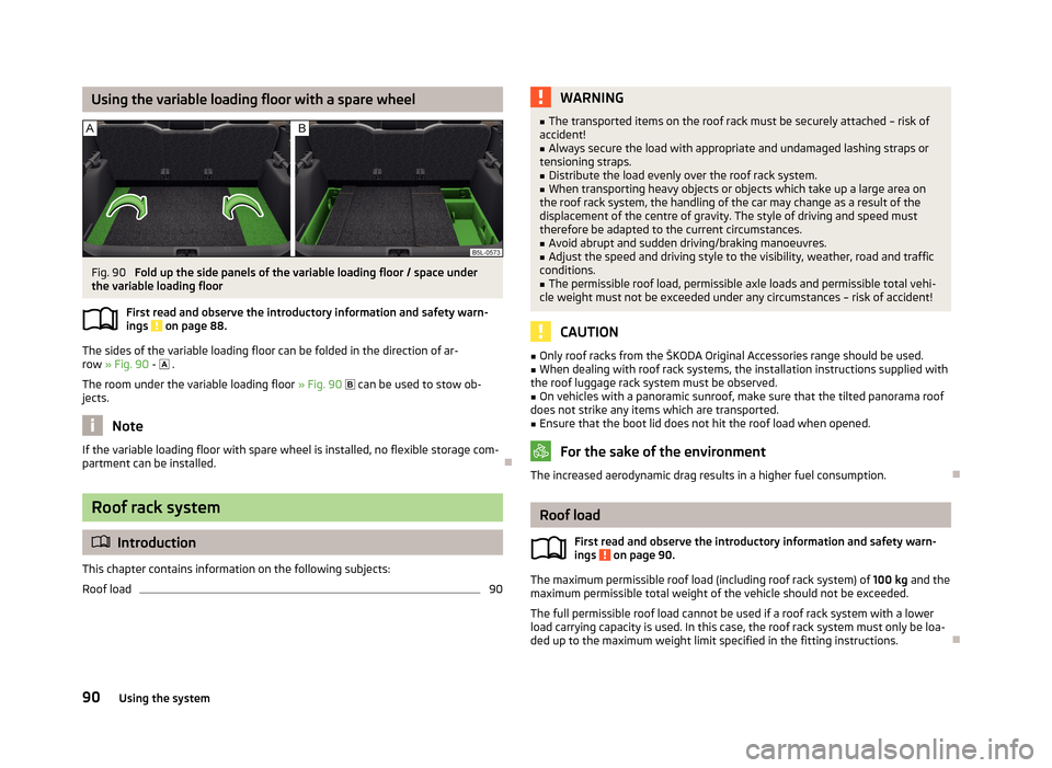
The sides of the variable loading floor can be folded in the direction of ar-row » Fig. 90 -
.
The room under the variable loading floor » Fig. 90
can be used to stow ob-
jects.
Note
If the variable loading floor with spare wheel is installed, no flexible storage com-
partment can be installed.
Roof rack system
Introduction
This chapter contains information on the following subjects:
Roof load
90WARNING■ The transported items on the roof rack must be securely attached – risk of
accident!■
Always secure the load with appropriate and undamaged lashing straps or
tensioning straps.
■
Distribute the load evenly over the roof rack system.
■
When transporting heavy objects or objects which take up a large area on
the roof rack system, the handling of the car may change as a result of the displacement of the centre of gravity. The style of driving and speed musttherefore be adapted to the current circumstances.
■
Avoid abrupt and sudden driving/braking manoeuvres.
■
Adjust the speed and driving style to the visibility, weather, road and traffic
conditions.
■
The permissible roof load, permissible axle loads and permissible total vehi-
cle weight must not be exceeded under any circumstances – risk of accident!
CAUTION
■ Only roof racks from the ŠKODA Original Accessories range should be used.■When dealing with roof rack systems, the installation instructions supplied with
the roof luggage rack system must be observed.■
On vehicles with a panoramic sunroof, make sure that the tilted panorama roof
does not strike any items which are transported.
■
Ensure that the boot lid does not hit the roof load when opened.
For the sake of the environment
The increased aerodynamic drag results in a higher fuel consumption.
Roof load
First read and observe the introductory information and safety warn-
ings
on page 90.
The maximum permissible roof load (including roof rack system) of 100 kg and the
maximum permissible total weight of the vehicle should not be exceeded.
The full permissible roof load cannot be used if a roof rack system with a lower
load carrying capacity is used. In this case, the roof rack system must only be loa-
ded up to the maximum weight limit specified in the fitting instructions.
90Using the system
Page 135 of 266
If an engine is only idling it takes much longer for it to reach its normal operating
temperature. Wear-and-tear and pollutant emissions, though, are particularly
high in the warming-up phase. Therefore, start driving as soon as the engine has
started, though high engine speeds should be avoided.
Avoiding short distances
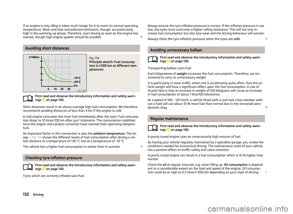
Fig. 114
Principle sketch: Fuel consump-
tion in l/100 km at different tem-
peratures
First read and observe the introductory information and safety warn- ings on page 130.
Short distances result in an above-average high fuel consumption. We therefore recommend avoiding distances of less than 4 km if the engine is cold.
A cold engine consumes the most fuel immediately after the start. Fuel consump-tion drops to 10 litres/100 km after just 1 kilometre. The consumption stabilises once the engine and catalytic converter have reached their operating tempera-
ture.
An important factor in this connection is also the ambient temperature. The im-
age » Fig. 114 shows the different levels of fuel consumption after driving a cer-
tain distance at a temperature of +20 °C and at a temperature of -10 °C.
The vehicle has a higher fuel consumption in winter than in summer.
Checking tyre inflation pressure
First read and observe the introductory information and safety warn-ings
on page 130.
Tyres which are correctly inflated save fuel.
Always ensure the tyre inflation pressure is correct. If the inflation pressure is too
low, the tyres must overcome a higher rolling resistance. This will not only in- crease fuel consumption but also tyre wear and the driving behaviour will worsen.
Always check the tyre inflation pressure when the tyres are cold.
Avoiding unnecessary ballast
First read and observe the introductory information and safety warn-
ings
on page 130.
Transporting ballast costs fuel.
Each kilogramme of weight increases the fuel consumption. Therefore, we rec-
ommend to carry no unnecessary weight.
It is particularly in town traffic, when one is accelerating quite often, that the ve-
hicle weight will have a significant effect upon the fuel consumption. A rule of
thumb here is that an increase in weight of 100 kilograms will cause an increase in fuel consumption of about 1 litre/100 kilometres.
At a speed of 100 - 120 km/h, a vehicle fitted with a roof rack cross member with-
out a load will use about 10 % more fuel than normal due to the increased aero- dynamic drag.
Regular maintenance
First read and observe the introductory information and safety warn-
ings
on page 130.
A poorly tuned engine uses an unnecessarily high amount of fuel.
By having your vehicle regularly maintained by a specialist garage, you create the conditions needed for economical driving. The maintenance state of your vehicle has a positive effect on traffic safety and value retention
A poorly tuned engine can result in a fuel consumption which is 10 % higher than normal.
Check the oil at regular intervals, e.g. when filling up. Oil consumption is depend-
ent to a considerable extent on the load and speed of the engine. Oil consump-
tion could be as high as 0.5 litres/1 000 km depending on your style of driving.
132Driving
Page 150 of 266
Driver steering intervention: Please take over steering!
The parking procedure is terminated due to a driver steering intervention. Park Assist finished. ASR deactivated.
The parking procedure cannot be carried out because the TCS system is deactiva- ted. Activate the TCS.
ASR deactivated. Please take over steering!
The parking procedure was ended because TCS was deactivated during the park-
ing procedure.
Trailer: Park Assist finished.
The parking procedure cannot be carried out because a trailer is hitched. Time limit exceeded. Please take over steering!
The parking procedure was ended because the time limit of 6 minutes was
passed.
Park Assist currently not available.
The system cannot be activated because a fault exists on the vehicle. Seek help
from a specialist garage.
Park Assist ended. System currently not available.
The parking procedure was ended because a fault exists on the vehicle. Seek help
from a specialist garage.
Park Assist faulty. Workshop!
The parking procedure is not possible because a fault exists in the system. Seek help from a specialist garage.
ASR intervention! Please take over steering!
The parking procedure is terminated by a TCS intervention. PARK ASSIST Turn on turn signal and select reverse gear
The prerequisites for manoeuvring out of a parking space using the system have
been met. Switch on the turn signals and shift into reverse.
Automatic space departure not possible. Space too small
The manoeuvring procedure using the system is not possible. The parking gap is too small.
Park Assist Brake interv. Speed too high
The driving speed during the parking procedure was too high - automatic brake
assist is initiated.
Cruise Control System
Introduction
This chapter contains information on the following subjects:
Activating/deactivating
148
Storing and maintaining speed
148
Changing the stored speed
148
Switching off temporarily
148
The Cruise Control System (CCS) maintains a set speed, more than 25 km/h, with-
out you having to actuate the accelerator pedal.
This is only possible within the range which is permitted by the power output and
braking power of the engine.
The warning light
illuminates in the instrument cluster when the cruise control
system is switched on.
WARNING■ For safety reasons, the cruise control system must not be used in dense
traffic or on unfavourable road surfaces (such as icy roads, slippery roads,
loose gravel) – risk of accident!■
The saved speed may only be resumed if it is not too high for the current
traffic conditions.
■
Always deactivate the cruise control system after use to prevent the system
being switched on unintentionally.
CAUTION
■ The cruise control system is not able to maintain a constant speed when driving
in areas with steeper gradients. The weight of the vehicle increases the speed at which it travels. In such cases, a lower gear should be engaged or the footbrake
applied.■
It is not possible to switch on the cruise control system if the first gear or re-
verse gear is engaged (Vehicles fitted with a manual transmission)
147Assist systems