air conditioning SKODA YETI 2015 1.G / 5L User Guide
[x] Cancel search | Manufacturer: SKODA, Model Year: 2015, Model line: YETI, Model: SKODA YETI 2015 1.G / 5LPages: 232, PDF Size: 30.84 MB
Page 112 of 232
WARNING■The auxiliary heating (auxiliary heating and ventilation) (hereinafter refer-
red to as aux. heating) must never be operated in closed rooms (e.g. garag-
es) – risk of poisoning!■
The auxiliary heating must not be allowed to run during refuelling – risk
of fire.
■
The exhaust pipe of the auxiliary heating is located on the underside of
the vehicle. If you want to use the heater, do not switch off the car in pla-
ces where the exhaust fumes can come into contact with flammable mate-
rials such as dry grass, undergrowth, leaves, spilled fuel etc. -. risk of fire.
CAUTION
■ The exhaust pipe of the auxiliary heating, which is located on the underside
of the vehicle, must not be clogged and the exhaust flow must not be blocked.■
If the auxiliary heating is running, the vehicle battery discharges. If the auxili-
ary heating and ventilation has been operated several times over a longer peri-
od, the vehicle must be driven a few kilometres in order to recharge the vehi-
cle battery.
■
The air inlet in front of the windscreen must be free (e.g. of ice, snow or
leaves) to ensure that the auxiliary heating operates properly.
Note
■ The auxiliary heating only switches the blower on, if it has achieved a coolant
temperature of approx. 50 °C.■
At low outside temperatures, this can result in a formation of water vapour in
the area of the engine compartment. This is quite normal and is not an operat-
ing problem.
■
So that warm air can flow into the vehicle interior after switching on the aux.
heating, you must maintain the comfort temperature normally selected by you,
leave the fan switched on and leave the air outlet vents in open. It is recom-
mended to put the air flow in the position
or
.
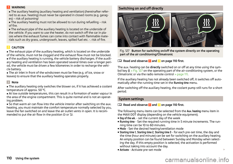
Switching on and off directlyFig. 127
Button for switching on/off the system directly on the operating
part of the air conditioning/Climatronic
Read and observe
and on page 110 first.
The aux. heating can be directly switched on or off at any time using the sym-
bol key
» Fig. 127 on the operating part of the air-conditioning system, or the
Climatronic or via the radio remote control » page 111.
If the auxiliary heating has not already been switched off, it switches off auto-
matically after the running time set in the
Running time
menu.
After switching off the auxiliary heating, the coolant pump still runs for a short
period.
System settings
Read and observe
and on page 110 first.
The following menu items can be selected from the
Aux. heating
menu item in
the MAXI DOT display (depending on the vehicle equipment). ■
Day of the wk.
- set the current day of the week
■
Running time
- Set the required running time in 5 minute increments. The run-
ning time can be 10 to 60 minutes.
■
Mode
- Set the desired heating/ventilation mode
■
Starting time 1
,
Starting time 2
,
Starting time 3
- for each pre-set time, the day and
the time (hour and minute) can be set for switching on the auxiliary heating.
An empty position can be found between Sunday and Monday when select-
ing the day. If this empty position is selected, the activation is performed
without taking into account the day.
■
Activate
- Activate pre-set mode
110Using the system
Page 120 of 232
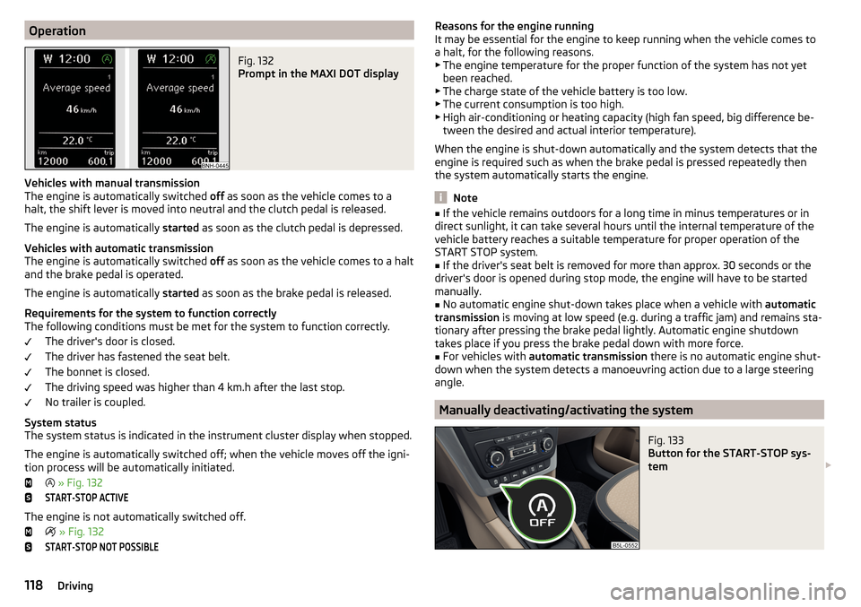
OperationFig. 132
Prompt in the MAXI DOT display
Vehicles with manual transmission
The engine is automatically switched off as soon as the vehicle comes to a
halt, the shift lever is moved into neutral and the clutch pedal is released.
The engine is automatically started as soon as the clutch pedal is depressed.
Vehicles with automatic transmission
The engine is automatically switched off as soon as the vehicle comes to a halt
and the brake pedal is operated.
The engine is automatically started as soon as the brake pedal is released.
Requirements for the system to function correctly
The following conditions must be met for the system to function correctly.
The driver's door is closed.
The driver has fastened the seat belt.
The bonnet is closed.
The driving speed was higher than 4 km.h after the last stop.
No trailer is coupled.
System status
The system status is indicated in the instrument cluster display when stopped.
The engine is automatically switched off; when the vehicle moves off the igni-
tion process will be automatically initiated.
» Fig. 132
START-STOP ACTIVE
The engine is not automatically switched off.
» Fig. 132
START-STOP NOT POSSIBLEReasons for the engine running
It may be essential for the engine to keep running when the vehicle comes to
a halt, for the following reasons. ▶ The engine temperature for the proper function of the system has not yet
been reached.
▶ The charge state of the vehicle battery is too low.
▶ The current consumption is too high.
▶ High air-conditioning or heating capacity (high fan speed, big difference be-
tween the desired and actual interior temperature).
When the engine is shut-down automatically and the system detects that the engine is required such as when the brake pedal is pressed repeatedly then
the system automatically starts the engine.
Note
■ If the vehicle remains outdoors for a long time in minus temperatures or in
direct sunlight, it can take several hours until the internal temperature of the
vehicle battery reaches a suitable temperature for proper operation of the
START STOP system.■
If the driver's seat belt is removed for more than approx. 30 seconds or the
driver's door is opened during stop mode, the engine will have to be started
manually.
■
No automatic engine shut-down takes place when a vehicle with automatic
transmission is moving at low speed (e.g. during a traffic jam) and remains sta-
tionary after pressing the brake pedal lightly. Automatic engine shutdown
takes place if you press the brake pedal down with more force.
■
For vehicles with automatic transmission there is no automatic engine shut-
down when the system detects a manoeuvring action due to a large steering
angle.
Manually deactivating/activating the system
Fig. 133
Button for the START-STOP sys-
tem
118Driving
Page 127 of 232
New tyres
New tyres must firstly be “run in”, as they do not offer optimal grip at first.
Therefore, drive especially carefully for the first 500 km or so.
New brake pads
New brake pads have to first “grind in” because these do not initially have the
best possible braking effect.
Therefore, drive especially carefully for the first 200 km or so.
Tips for economical driving
To achieve the lowest possible fuel consumption, the following instructions
must be observed.
Looking ahead when driving
Avoid unnecessary acceleration and braking.
Switch in an energy saving and timely manner Observe the recommended gear » page 40.
Avoid full throttle and high speeds
Fuel consumption can be reduced by half if only three-quarters of the possible
top speed of your vehicle is used.
Reducing idling
If the vehicle is fitted with the START - STOP system there is an automatic re-
duction of the idling. If the engine is stopped on vehicles without START-STOP
system, such as when waiting in a traffic jam, the fuel economy is already
greater after 30 - 40 s than the fuel quantity which is required for engine re-
start.
Avoid short distances
When driving a short distance of less than about 4 km, the engine cannot
reach its operating temperature. As long as the engine has not reached oper-
ating temperature, the fuel consumption is significantly higher than with the
engine hot.
Pay attention to the correct tyre inflation pressure being maintained
Further information » page 176.
Avoid unnecessary ballast
Per 100 kg of weight, consumption increases by about 0.3 l/100 km. At a speed
of 100 - 120 km/h, a vehicle fitted with a roof rack cross member without a load
will use about 10 % more fuel than normal due to the increased aerodynamic
drag.
Saving electricity
Only turn on electrical consumers (e.g. seat, window and mirror heating, etc.)
for as long as necessary.
Use the cooling system economically
The air conditioning system compressor uses power from the engine when in
cooling mode, which will affect the fuel consumption.
It recommended to open the windows or the doors of a vehicle for which the
interior has been strongly heated through the effect of direct sunlight in order
to allow the heated air to escape.
The cooling system should not be on if the windows are open.
Avoiding damage to your vehicle
Introduction
This chapter contains information on the following subjects:
Driving Tips
125
Driving through water
126
This section of the manual contains important information on preventing dam-
age to the vehicle while driving.
Driving Tips
Only drive on such roads and in such terrain, which match the vehicle parame-
ters » page 204 , Technical data as well as your driving skills.
The driver is always responsible for deciding whether the vehicle can handle
travelling in the given terrain.
When travelling off paved roads, we recommend activating the OFF ROAD
mode » page 129 .
125Starting-off and Driving
Page 199 of 232
CAUTION■“Never repair” fuses, and do not replace them with fuses of a higher amper-
age – risk of fire! This may also cause damage at another part of the electrical
system.■
If a newly inserted fuse blows again after a short time, have the electrical
system checked as quickly as possible by a specialist garage.
■
A blown fuses is recognisable by the molten metal strip. Replace the faulty
fuse with a new one of the same amperage.
Note
■
We recommend always carrying replacement fuses in the vehicle. A box of
replacement fuses and bulbs can be purchased from ŠKODA Original Accesso-
ries.■
There can be several power consuming devices for one fuse.
■
Multiple fuses may exist for a single power consuming device.
Fuses in the dash panel
Fig. 201
Distribution board cover.
Read and observe and on page 196 first.
The fuses are located on the left side of the dash panel behind a cover.
Replacing fuses
›
Insert a screwdriver into the opening in the cover in the direction of the ar-
row » Fig. 201 .
›
Remove the cover of the fuse box and remove.
›
Remove the plastic clip from the holder in the fuse box cover in the dash
panel.
›
Place the clip on the respective fuse and pull this fuse out.
›
Insert a new fuse.
›
Replace the bracket at the original position.
›
Re-insert the cover of the fuse box .
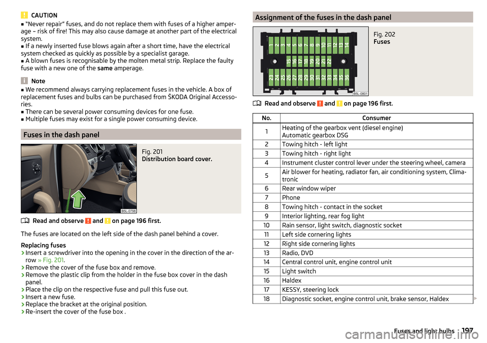
Assignment of the fuses in the dash panelFig. 202
Fuses
Read and observe and on page 196 first.
No.Consumer1Heating of the gearbox vent (diesel engine)
Automatic gearbox DSG2Towing hitch - left light3Towing hitch - right light4Instrument cluster control lever under the steering wheel, camera5Air blower for heating, radiator fan, air conditioning system, Clima-
tronic6Rear window wiper7Phone8Towing hitch - contact in the socket9Interior lighting, rear fog light10Rain sensor, light switch, diagnostic socket11Left side cornering lights12Right side cornering lights13Radio, DVD14Central control unit, engine control unit15Light switch16Haldex17KESSY, steering lock18Diagnostic socket, engine control unit, brake sensor, Haldex 197Fuses and light bulbs
Page 200 of 232
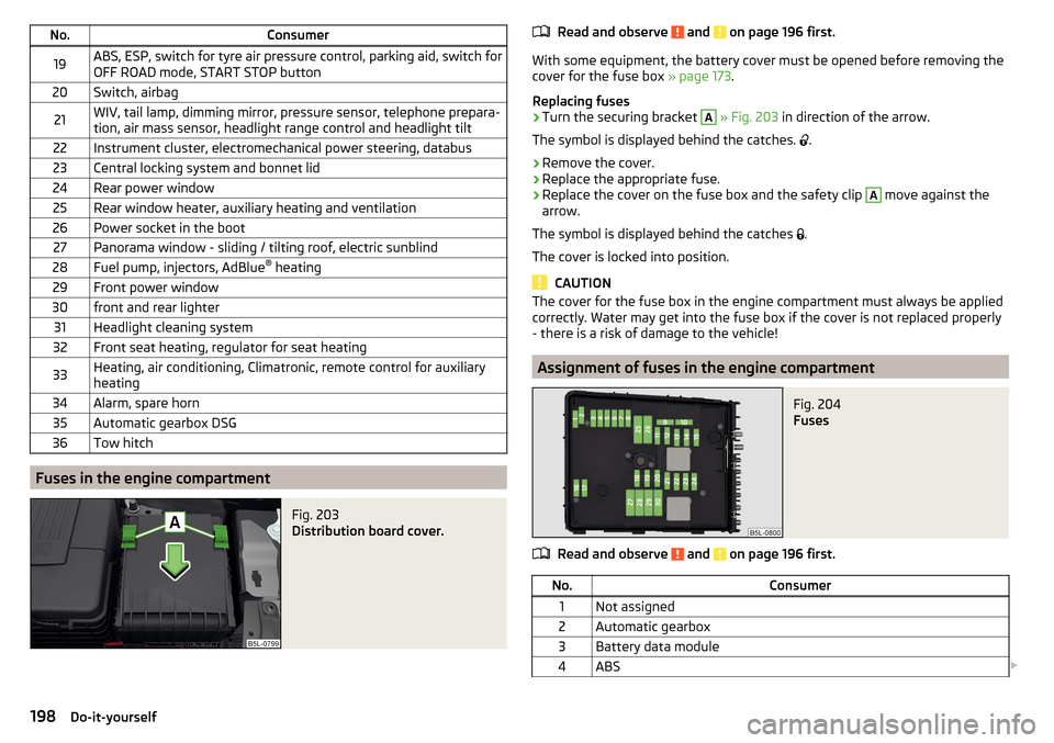
No.Consumer19ABS, ESP, switch for tyre air pressure control, parking aid, switch for
OFF ROAD mode, START STOP button20Switch, airbag21WIV, tail lamp, dimming mirror, pressure sensor, telephone prepara-
tion, air mass sensor, headlight range control and headlight tilt22Instrument cluster, electromechanical power steering, databus23Central locking system and bonnet lid24Rear power window25Rear window heater, auxiliary heating and ventilation26Power socket in the boot27Panorama window - sliding / tilting roof, electric sunblind28Fuel pump, injectors, AdBlue ®
heating29Front power window30front and rear lighter31Headlight cleaning system32Front seat heating, regulator for seat heating33Heating, air conditioning, Climatronic, remote control for auxiliary
heating34Alarm, spare horn35Automatic gearbox DSG36Tow hitch
Fuses in the engine compartment
Fig. 203
Distribution board cover.
Read and observe and on page 196 first.
With some equipment, the battery cover must be opened before removing the
cover for the fuse box » page 173.
Replacing fuses
›
Turn the securing bracket
A
» Fig. 203 in direction of the arrow.
The symbol is displayed behind the catches.
.
›
Remove the cover.
›
Replace the appropriate fuse.
›
Replace the cover on the fuse box and the safety clip
A
move against the
arrow.
The symbol is displayed behind the catches .
The cover is locked into position.
CAUTION
The cover for the fuse box in the engine compartment must always be applied
correctly. Water may get into the fuse box if the cover is not replaced properly
- there is a risk of damage to the vehicle!
Assignment of fuses in the engine compartment
Fig. 204
Fuses
Read and observe and on page 196 first.
No.Consumer1Not assigned2Automatic gearbox3Battery data module4ABS 198Do-it-yourself
Page 206 of 232
Technical data
Technical data
Basic vehicle data
Introduction
This chapter contains information on the following subjects:
Vehicle characteristics
204
Operating weight
205
Payload
205
Measurement of fuel consumption and CO 2 emissions according to ECE
Regulations and EU Directives
206
Dimensions
207
angle and gradeability
208
The details given in the vehicle's technical documentation always take prece-
dence over the details in the Owner's Manual.
The listed performance values were determined without performance-reduc- ing equipment, e.g. air conditioning system.
The values given have been determined in accordance with regulations and in
conditions prescribed by legal or technical provisions for determining the oper-
ating and technical data of vehicles.
The values listed are for the basic model without optional equipment.
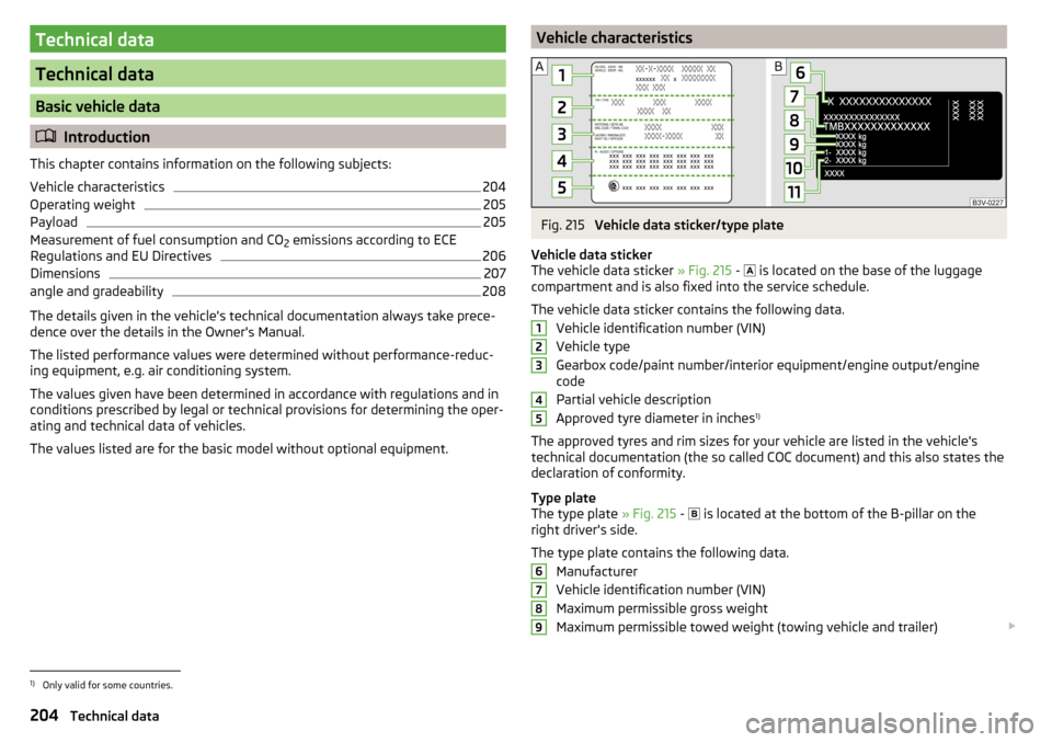
Vehicle characteristicsFig. 215
Vehicle data sticker/type plate
Vehicle data sticker
The vehicle data sticker » Fig. 215 -
is located on the base of the luggage
compartment and is also fixed into the service schedule.
The vehicle data sticker contains the following data. Vehicle identification number (VIN)
Vehicle type
Gearbox code/paint number/interior equipment/engine output/engine code
Partial vehicle description
Approved tyre diameter in inches 1)
The approved tyres and rim sizes for your vehicle are listed in the vehicle's
technical documentation (the so called COC document) and this also states the
declaration of conformity.
Type plate
The type plate » Fig. 215 -
is located at the bottom of the B-pillar on the
right driver's side.
The type plate contains the following data. Manufacturer
Vehicle identification number (VIN)
Maximum permissible gross weight
Maximum permissible towed weight (towing vehicle and trailer)
1234567891)
Only valid for some countries.
204Technical data
Page 207 of 232
Maximum permissible front axle load
Maximum permissible rear axle load
Vehicle identification number (VIN)
The vehicle identification number - VIN (vehicle body number) is stamped into
the engine compartment on the right hand suspension strut dome. This num-
ber is also located on a sign on the lower left hand edge below the windscreen
(together with a VIN bar code), and on the type plate.
Engine number
The engine number (three-digit identifier and serial number) is stamped on the
engine block.
Supplementary Information (applies to Russia)
The full type approval number of the means of transport is indicated in the
registration documents, field 17.
Maximum permissible trailer weight
The listed maximum permissible trailer weight is only valid for altitudes up to 1000 m above sea level.
The engine output falls as altitude increases, as does the vehicle's climbing
power. Therefore, for every additional 1000 m in height (or part), the maximum
permissible towed weight must be reduced by 10%.
The towed weight is made up of the actual weights of the loaded towing vehi-
cle and the loaded trailer.WARNINGDo not exceed the specified maximum permissible weights – risk of acci-
dent and damage!
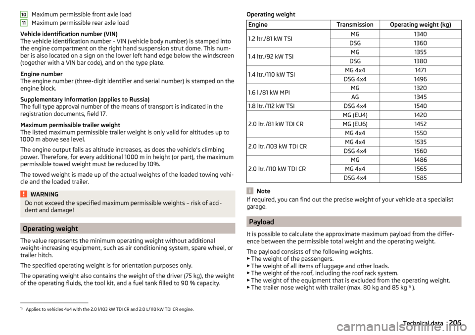
Operating weight
The value represents the minimum operating weight without additional
weight-increasing equipment, such as air conditioning system, spare wheel, or trailer hitch.
The specified operating weight is for orientation purposes only.
The operating weight also contains the weight of the driver (75 kg), the weight
of the operating fluids, the tool kit, and a fuel tank filled to 90 % capacity.
1011Operating weightEngineTransmissionOperating weight (kg)1.2 ltr./81 kW TSIMG1340DSG13601.4 ltr./92 kW TSIMG1355DSG13801.4 ltr./110 kW TSIMG 4x41471DSG 4x414961.6 l./81 kW MPIMG1320AG13451.8 ltr./112 kW TSIDSG 4x41540
2.0 ltr./81 kW TDI CR
MG (EU4)1420MG (EU6)1452MG 4x415502.0 ltr./103 kW TDI CRMG 4x41535DSG 4x41560
2.0 ltr./110 kW TDI CR
MG1486MG 4x41565DSG 4x41585
Note
If required, you can find out the precise weight of your vehicle at a specialist
garage.
Payload
It is possible to calculate the approximate maximum payload from the differ-
ence between the permissible total weight and the operating weight.
The payload consists of the following weights.
▶ The weight of the passengers.
▶ The weight of all items of luggage and other loads.
▶ The weight of the roof, including the roof rack system.
▶ The weight of the equipment that is excluded from the operating weight.
▶ The trailer nose weight with trailer (max. 80 kg and 85 kg 1)
).
1)
Applies to vehicles 4x4 with the 2.0 l/103 kW TDI CR and 2.0 L/110 kW TDI CR engine.
205Technical data
Page 215 of 232
Index
A
abroad lead-free petrol
161
Abroad Headlights
69
ABS Operation
127
Warning light36
Acceptance and recycling of used vehicles152
Accessories149
Adaptive headlight see xenon headlight
66
AdBlue163, 164
refilling163
replenish164
adjusting auxiliary heating and ventilation
110
Adjusting Exterior mirrors
74
Head restraints79
Steering wheel9
Adjusting the seats8
adjustment Front seat
75
Adjustment Headlight beam
64
Seats76
AFS Display messages
36
Warning light36
AHL see xenon headlight
66
Air-conditioning system Air outlet vents
108
Airbag15
Deactivating19
Deactivating the front passenger airbag20
Deployment15
Front airbag16
Head airbag19
Knee airbag17
Modifications and damage to the airbag system 151
Side airbag
18
Warning light37
Airbag system15
Air conditioning104
Air distribution control107
Climatronic106
Manual air conditioning105
Air distribution control107
Air outlet vents108
Alarm Enable/disable
56
Switch off56
Trailer148
Triggering56
Alcantara cleaning
158
Alternator Warning light
33
Anodized parts Refer to vehicle maintenance
155
Anti-lock braking system (ABS)127
Anti-theft alarm system Enable/disable
56
Trailer148
Anti-theft wheel bolts184
Armrest Front
78
artificial leather158
Ashtray87
ASR warning light
35
Assistance systems OFF ROAD-mode
129
Assist systems127
ABS36
ASR35
ESC35
Auto Check Control31
Automatic driving lamp control66
Automatic gearbox Manual shifting of gears
123
Selector lever-emergency unlocking195
Selector lever lock123
Starting-off and driving124
Tiptronic123
Using the selector lever122
Automatic gearbox modes122
Automatic load deactivation175
automatic transmission selector lever lock defect
123
Automatic transmission122
Kickdown124
Selector lever lock123
AUX94
Auxiliary heating and ventilation Switching on and off directly
110
System settings110
Auxiliary heating (auxiliary heating and ventila- tion)
109
Auxiliary heating (aux. heating and ventilation) Radio remote control
111
Avoiding damage to your vehicle125
B
Ball head Check fitting
144
Ready position142, 143
Ball rod installing
143
removing144
Bar with sliding hook98
213Index
Page 220 of 232
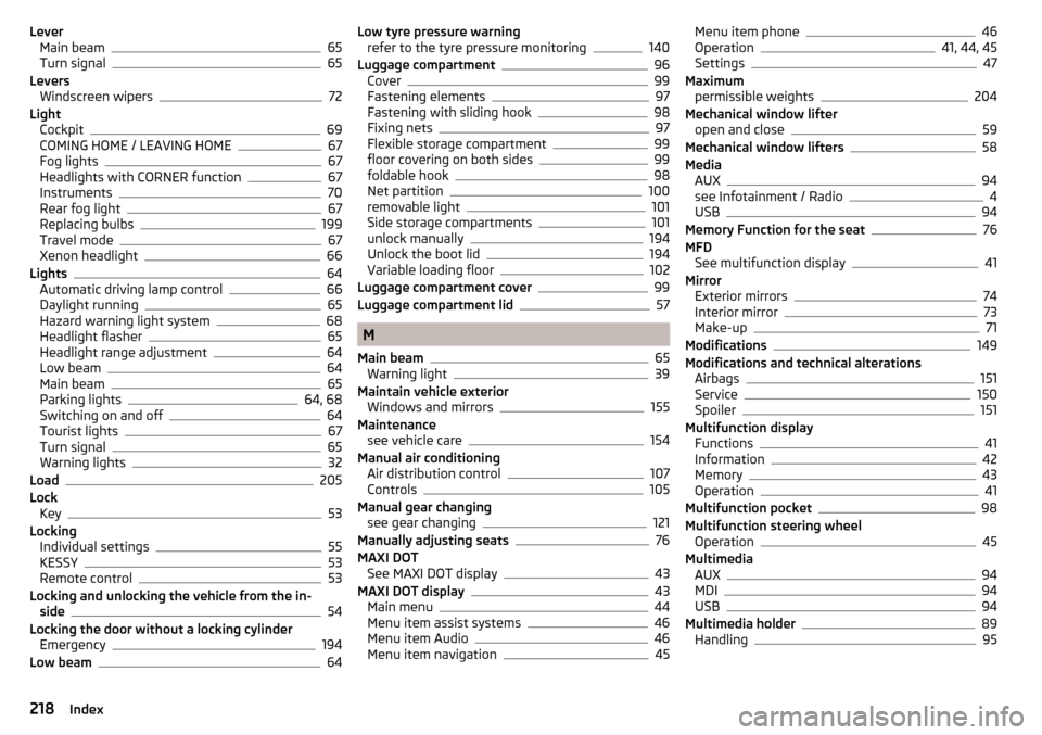
LeverMain beam65
Turn signal65
Levers Windscreen wipers
72
Light Cockpit
69
COMING HOME / LEAVING HOME67
Fog lights67
Headlights with CORNER function67
Instruments70
Rear fog light67
Replacing bulbs199
Travel mode67
Xenon headlight66
Lights64
Automatic driving lamp control66
Daylight running65
Hazard warning light system68
Headlight flasher65
Headlight range adjustment64
Low beam64
Main beam65
Parking lights64, 68
Switching on and off64
Tourist lights67
Turn signal65
Warning lights32
Load205
Lock Key
53
Locking Individual settings
55
KESSY53
Remote control53
Locking and unlocking the vehicle from the in- side
54
Locking the door without a locking cylinder Emergency
194
Low beam64
Low tyre pressure warning refer to the tyre pressure monitoring140
Luggage compartment96
Cover99
Fastening elements97
Fastening with sliding hook98
Fixing nets97
Flexible storage compartment99
floor covering on both sides99
foldable hook98
Net partition100
removable light101
Side storage compartments101
unlock manually194
Unlock the boot lid194
Variable loading floor102
Luggage compartment cover99
Luggage compartment lid57
M
Main beam
65
Warning light39
Maintain vehicle exterior Windows and mirrors
155
Maintenance see vehicle care
154
Manual air conditioning Air distribution control
107
Controls105
Manual gear changing see gear changing
121
Manually adjusting seats76
MAXI DOT See MAXI DOT display
43
MAXI DOT display43
Main menu44
Menu item assist systems46
Menu item Audio46
Menu item navigation45
Menu item phone46
Operation41, 44, 45
Settings47
Maximum permissible weights
204
Mechanical window lifter open and close
59
Mechanical window lifters58
Media AUX
94
see Infotainment / Radio4
USB94
Memory Function for the seat76
MFD See multifunction display
41
Mirror Exterior mirrors
74
Interior mirror73
Make-up71
Modifications149
Modifications and technical alterations Airbags
151
Service150
Spoiler151
Multifunction display Functions
41
Information42
Memory43
Operation41
Multifunction pocket98
Multifunction steering wheel Operation
45
Multimedia AUX
94
MDI94
USB94
Multimedia holder89
Handling95
218Index