boot SKODA YETI 2015 1.G / 5L User Guide
[x] Cancel search | Manufacturer: SKODA, Model Year: 2015, Model line: YETI, Model: SKODA YETI 2015 1.G / 5LPages: 232, PDF Size: 30.84 MB
Page 57 of 232
This function is pointed out by the following message on the instrument clus-
ter display after switching off the ignition.Check SAFELOCK! Owner´s manual!CHECK DEADLOCK
After locking the vehicle, the warning light in the driver's door flashes for
around 2 seconds in quick succession, afterwards it begins to flash evenly at
longer intervals.
Switching off
The safe lock can be switched off in one of the following ways.
▶ By locking twice within 2 seconds.
▶ By disabling the button for interior monitoring and anti-towing » page 57,
Interior monitor and towing protection .
The indicator light in the driver door flashes for about 2 seconds fast, goes out and starts to flash at longer intervals after about 30 seconds.
If the vehicle is locked and the safe securing system is switched off, the door
can be opened separately from the inside by a single pull on opening lever.
The Safelock system switches back on when the vehicle is locked.
WARNINGIf the car is locked and the safe securing system activated, no people must
remain in the car as it will then not be possible to either unlock a door or
open a window from the inside. The locked doors make it more difficult for
rescuers to get into the vehicle in an emergency – risk to life!
Individual settings
Read and observe
and on page 52 first.
The following central locking functions can be individually set via the MAXI
DOT display » page 47, Menu item
Settings
.
Opening a single door
The function allows you to unlock only the driver's door and the fuel filler flap
with the radio remote control. KESSY makes it possible to release individual
doors as well as the fuel filler flap, depending on the area in which the key is
located. The other doors and the boot lid are only unlocked when the unlock-
ing is repeated.
Unlocking a vehicle side door
This function enables you to unlock both doors on the driver's side and the
fuel filler flap with the radio remote control unit. KESSY makes it possible to
release of both doors on one side as well as the fuel filler flap, depending on
the area in which the key is located. The other doors and the boot lid are only
unlocked when the unlocking is repeated.
Unlock all doors
The function allows you to unlock all doors, the boot lid and the fuel filler flap.
Automatic locking/unlocking
The function allows you to lock all doors and the boot lid from a speed of
about 15 km/h. The button in the handle of the boot lid is deactivated.
All doors and the boot lid are automatically unlocked again by removing the ig-
nition key or by opening any of the doors. In vehicles with the KESSY system,
this is when any door is opened.
The vehicle can also be unlocked by pressing the Central Locking Button in
the centre console » page 54.
Acoustic signals when locking / unlocking
For vehicles with anti-theft alarm system, the acoustic signals can be activa-
ted / deactivated by means of the MAXI DOT display » page 47.
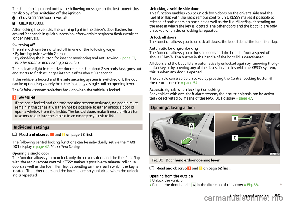
Opening/closing a door
Fig. 38
Door handle/door opening lever:
Read and observe
and on page 52 first.
Opening from the outside
›
Unlock the vehicle.
›
Pull on the door handle
A
in the direction of the arrow » Fig. 38.
55Unlocking and opening
Page 58 of 232
Opening from the inside›Pull on door opening lever B of the door and push the door away from you.
Closing from the inside›
Grasp pull handle
C
and close the door.
WARNING■ Make sure that the door has closed correctly as it can open suddenly
while driving – risk of death!■
Only open and close the door when there is no one in the opening/closing
range – risk of injury!
■
An opened door can close automatically if there is a strong wind or the
vehicle is on an incline – risk of injury!
■
Never drive with the doors open - it can be fatal!
Child safety lock
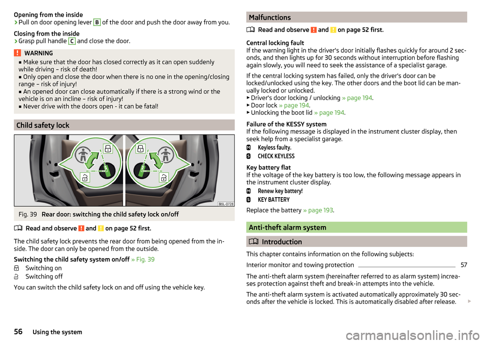
Fig. 39
Rear door: switching the child safety lock on/off
Read and observe
and on page 52 first.
The child safety lock prevents the rear door from being opened from the in-
side. The door can only be opened from the outside.
Switching the child safety system on/off » Fig. 39
Switching on
Switching off
You can switch the child safety lock on and off using the vehicle key.
Malfunctions
Read and observe
and on page 52 first.
Central locking fault
If the warning light in the driver's door initially flashes quickly for around 2 sec-
onds, and then lights up for 30 seconds without interruption before flashing
again slowly, you will need to seek the assistance of a specialist garage.
If the central locking system has failed, only the driver's door can be
locked/unlocked using the key. The other doors and the boot lid can be man-
ually locked or unlocked.
▶ Driver's door locking / unlocking » page 194.
▶ Door lock » page 194 .
▶ Unlocking the boot lid » page 194.
Failure of the KESSY system
If the following message is displayed in the instrument cluster display, then seek help from a specialist garage.
Keyless faulty.CHECK KEYLESS
Key battery flat
If the voltage of the key battery is too low, the following message appears in
the instrument cluster display.
Renew key battery!KEY BATTERY
Replace the battery » page 193.
Anti-theft alarm system
Introduction
This chapter contains information on the following subjects:
Interior monitor and towing protection
57
The anti-theft alarm system (hereinafter referred to as alarm system) increa-
ses protection against theft and break-in attempts into the vehicle.
The anti-theft alarm system is activated automatically approximately 30 sec-
onds after the vehicle is locked. This is automatically disabled after release.
56Using the system
Page 59 of 232
The alarm system triggers audible and visual signals if an attempt is made to
break into the vehicle (hereafter referred to as alarm).
Triggering the alarm
The alarm is triggered when the following unauthorized actions are carried out
on the locked vehicle.
▶ Opening the bonnet.
▶ Opening the boot lid.
▶ Opening the doors.
▶ Manipulation of the ignition lock.
▶ Towing the vehicle.
▶ Movement in the vehicle.
▶ Sudden and significant voltage drop of the electrical system.
▶ Uncoupling the trailer.
If the driver's door of a vehicle is unlocked and opened by the lock cylinder,
then the alarm is triggered.
Switching off the alarm
The alarm is turned off by pressing the button on the key or switching on
the ignition.
CAUTION
Before leaving the vehicle, it must be checked that all of the windows, doors
and the sliding/tilting roof are locked in order to ensure the full functionality of
the anti-theft alarm system.
Note
The alarm system has its own power source. The working life of the power
supply source is 5 years.
Interior monitor and towing protection
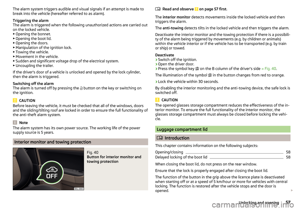
Fig. 40
Button for interior monitor and
towing protection
Read and observe on page 57 first.
The interior monitor detects movements inside the locked vehicle and then
triggers the alarm.
The anti-towing detects tilts in the locked vehicle and then triggers the alarm.
Deactivate the interior monitor and the towing protection if there is a possibili-
ty of the alarm being triggered by movements (e.g. by children or animals)
within the vehicle interior or if the vehicle has to be transported (e.g. by train
or ship) or towed.
Deactivate
›
Switch off the ignition.
›
Open the driver door.
›
Press the symbol key on the B column of the driver's side
» Fig. 40.
The illumination of the symbol in the button changes from red to orange.
›
Lock the vehicle within 30 seconds.
By disabling the interior monitoring and the anti-towing device, the safe lock is
switched off.
CAUTION
The opened glasses storage compartment reduces the effectiveness of the in-
terior monitor. To ensure the full functionality of the interior monitor, the
glasses storage compartment must always be closed before locking the vehi-
cle.
Luggage compartment lid
Introduction
This chapter contains information on the following subjects:
Opening/closing
58
Delayed locking of the boot lid
58
When closing the boot lid, do not press on the rear window.
Ensure that the lock is properly engaged after closing the boot lid.
The function of the button in the grip above the licence plate is deactivated when starting off or at a speed of 5 km/hour or more for vehicles with central
locking. The function is restored after the vehicle stops and the door is
opened.
57Unlocking and opening
Page 60 of 232
WARNING■Never drive with the boot lid open or ajar, as otherwise exhaust gases
may get into the interior of the vehicle – risk of poisoning!■
Make sure that when closing the boot lid, no body parts are crushed -
there is danger of injury!
Opening/closing
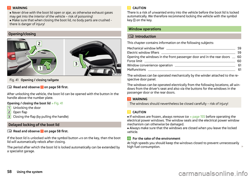
Fig. 41
Opening / closing tailgate
Read and observe
on page 58 first.
After unlocking the vehicle, the boot lid can be opened with the button in the
handle above the number plate.
Opening / closing the boot lid » Fig. 41
Unlocking the door
Open flap
Closing the flap (by pulling the handle)
Delayed locking of the boot lid
Read and observe
on page 58 first.
If the boot lid is unlocked with the symbol button on the key, then the boot
lid will automatically relock after closing.
The period after which the boot lid is locked automatically can be extended by
a specialist garage.
123CAUTIONThere is a risk of unwanted entry into the vehicle before the boot lid is locked
automatically. We therefore recommend locking the vehicle with the symbol
key
on the key.
Window operations
Introduction
This chapter contains information on the following subjects:
Mechanical window lefter
59
Electric window lifters
59
Opening the windows in the front passenger door and in the rear doors
60
Force limit
60
Window convenience operation
61
Malfunctions
61
The windows can be operated mechanically by the winder attached to the re-
spective door panel.
The windows can be operated electrically from the following locations; all win-
dows from the driver's seat and also via the buttons for the windows in the
passenger door or the rear doors.
WARNINGThe windows should nevertheless be closed carefully – risk of injury!
CAUTION
■ If windows are frozen, always remove ice » page 155 before operating the
electrical power windows. The window seals and the electrical power window
mechanism can otherwise be damaged.■
Always make sure that the windows are closed when you leave the locked
vehicle.
For the sake of the environment
At high speeds you should keep the windows closed to prevent unnecessarily high fuel consumption. 58Using the system
Page 66 of 232
Lights and visibility
Lights
Introduction
This chapter contains information on the following subjects:
Operating the lights
64
Daylight running lights (DAY LIGHT)
65
Turn signal and main beam
65
Automatic driving lamp control
66
Xenon headlight
66
Front and rear fog light
67
Fog lights with the CORNER function
67
COMING HOME / LEAVING HOME
67
Hazard warning light system
68
Parking lights
68
Driving abroad
69
Unless otherwise stated, the lights only work when the ignition is switched on.
The arrangement of the controls right-hand drive models may differ from the
layout shown in » Fig. 47 on page 64 . The symbols which mark the positions
of the controls are identical.
Keep the headlights lenses clean » page 155, Headlight glasses .
WARNINGThe automatic driving lamp control only operates as a support and
does not release the driver from his responsibility to check the lights and, if
necessary, to switch on the light depending on the prevailing light condi-
tions.
Note
The headlights may mist up temporarily. When the driving lights are switched
on, the light outlet surfaces are free from mist after a short period, although
the headlight lenses may still be misted up in the peripheral areas. This mist
has no influence on the life of the lighting system.Operating the lightsFig. 47
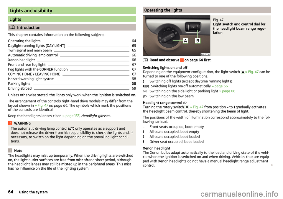
Light switch and control dial for
the headlight beam range regu-
lation
Read and observe on page 64 first.
Switching lights on and off
Depending on the equipment configuration, the light switch
A
» Fig. 47 can be
turned to one of the following positions.
Switching off lights (except daytime running lights)Switching lights on/off automatically » page 66
Switching on the side light or parking light » page 68
Switching on the low beam
Headlight range control
Turning the rotary switch
B
» Fig. 47 from position
to
gradually activates
the headlight beam control, thereby shortening the beam of light.
The positions of the width of illumination correspond approximately to the fol- lowing car load.
Front seats occupied, boot empty
All seats occupied, boot empty
All seats occupied, boot loaded
Driver seat occupied, boot loaded
Xenon headlight
The Xenon bulbs adapt automatically to the load and driving state of the vehi-
cle when the ignition is switched on and when driving. Vehicles that are equip-
ped with Xenon headlights do not have a manual headlight range adjustment
control.
64Using the system
Page 73 of 232
Note■If the on-board voltage decreases, the heating switches off automatically
» page 175 , Automatic load deactivation .■
If the light is flashing inside the button the heater is off due to low battery.
■
The position and shape of the switch may vary according to the equipment
fitted.
Sun visors in the front
Fig. 57
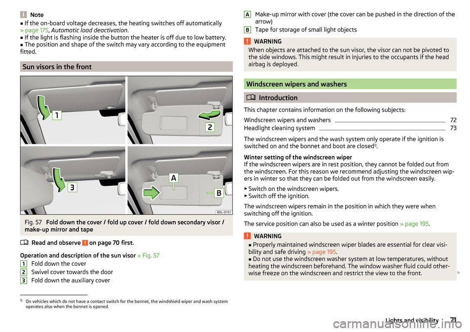
Fold down the cover / fold up cover / fold down secondary visor /
make-up mirror and tape
Read and observe
on page 70 first.
Operation and description of the sun visor » Fig. 57
Fold down the cover
Swivel cover towards the door
Fold down the auxiliary cover
123Make-up mirror with cover (the cover can be pushed in the direction of the
arrow)
Tape for storage of small light objectsWARNINGWhen objects are attached to the sun visor, the visor can not be pivoted to
the side windows. This might result in injuries to the occupants if the head
airbag is deployed.
Windscreen wipers and washers
Introduction
This chapter contains information on the following subjects:
Windscreen wipers and washers
72
Headlight cleaning system
73
The windscreen wipers and the wash system only operate if the ignition is
switched on and the bonnet and boot are closed 1)
.
Winter setting of the windscreen wiper
If the windscreen wipers are in rest position, they cannot be folded out from
the windscreen. For this reason we recommend adjusting the windscreen wip-
ers in winter so that they can be folded out from the windscreen easily.
▶ Switch on the windscreen wipers.
▶ Switch off the ignition.
The windscreen wipers remain in the position in which they were when
switching off the ignition.
The service position can also be used as a winter position » page 195.
WARNING■
Properly maintained windscreen wiper blades are essential for clear visi-
bility and safe driving » page 195.■
Do not use the windscreen washer system at low temperatures, without
heating the windscreen beforehand. The window washer fluid could other-
wise freeze on the windscreen and restrict the view to the front.
AB1)
On vehicles which do not have a contact switch for the bonnet, the windshield wiper and wash system
operates also when the bonnet is opened.
71Lights and visibility
Page 85 of 232
›Press the lever in direction of arrow 1
» Fig. 75 and fold back the seat back-
rest in the direction of arrow 2.›
Check for yourself that the seat backrest is engaged by pulling on it.
›
Remove the tongue of the lock from the safety position.
WARNING■ After folding back the seat, the seat belts must be ready for use.■The seat backrests must be securely engaged so that objects from the
boot cannot slip into the passenger compartment on sudden braking – risk
of injury!■
When folding the seat backrest always make sure that it has safely
locked into position, this is confirmed by the position and a visible marking
on the cover of the lever.
Transporting and practical equipment
Useful equipment
Introduction
This chapter contains information on the following subjects:
Car park ticket holder
84
Storage compartment on the dash panel
84
stowage compartments in the doors
85
Storage compartment in the front centre console
85
Cup holders
85
Cigarette lighter
86
Ashtray
87
12-Volt power outlet
88
Waste container
88
Multimedia holder
89
Storage compartment under the front arm rest
90
storage net in the front centre console
90
Glasses compartment
90
Storage compartment on the front passenger side
91
Storage compartment under the passenger seat
91
Clothes hook
92
Storage pockets on the front seats
92
Storage compartment in the rear centre console
92
Folding table on front seat backrest
93
folding table at the centre backrest
93
Removable through-loading bag
93
AUX, USB and MDI inputs
94
83Transporting and practical equipment
Page 96 of 232
›Place the empty through-loading bag in the gap between the front and rear
seats in such a way that the end of the bag with the zip lies in the boot.›
Open the boot lid.
›
Push the skis into the through-loading bag from the boot » .
›
Close the through-loading bag.
Securing through-loading bag and skis
›
Pull the securing belt with both lock tongues out of the pocket of the
through-loading bag.
›
Insert the lock tongues
A
» Fig. 99 in the belt locks of the rear middle seat
belt
C
, first on the one side and then on the other side.
›
Place the securing belt in the middle of the skis between the heel and the tip
of the bindings and pull the securing belt tight at the free end of the belt
B
.
WARNING■ After placing the skis into the through-loading bag, you must secure the
through-loading bag with the securing belt.■
The securing belt must hold the skis tight.
■
Ensure that the securing belt for skis grasps the middle between the tip
and the heel element of the binding (see also marking on the through-load-
ing bag).
■
The total weight of the skis which are transported must not exceed 10 kg.
CAUTION
■ Never fold and stow the through-loading bag wet - risk of damaging the
through-loading bag.■
The through-loading bag is designed for the transportation of a maximum of
two pairs of skis.
■
Place the skis and sticks in the through-loading bag with the tips facing to
the rear.
AUX, USB and MDI inputsFig. 100
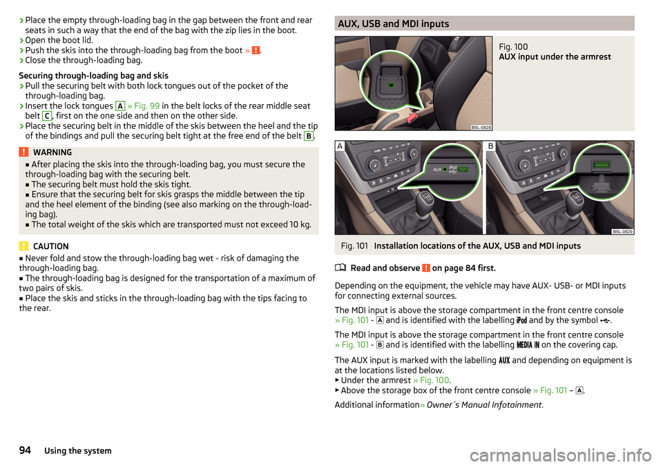
AUX input under the armrest
Fig. 101
Installation locations of the AUX, USB and MDI inputs
Read and observe
on page 84 first.
Depending on the equipment, the vehicle may have AUX- USB- or MDI inputs
for connecting external sources.
The MDI input is above the storage compartment in the front centre console
» Fig. 101 -
and is identified with the labelling
and by the symbol
.
The MDI input is above the storage compartment in the front centre console
» Fig. 101 -
and is identified with the labelling
on the covering cap.
The AUX input is marked with the labelling
and depending on equipment is
at the locations listed below. ▶ Under the armrest » Fig. 100.
▶ Above the storage box of the front centre console » Fig. 101 –
.
Additional information » Owner´s Manual Infotainment .
94Using the system
Page 101 of 232
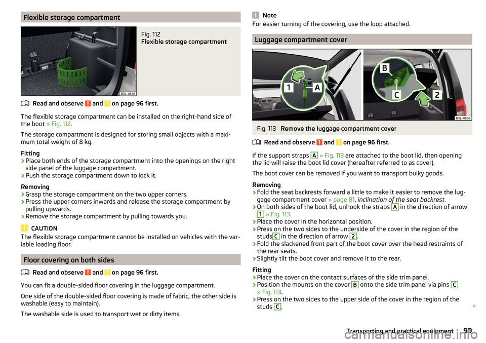
Flexible storage compartmentFig. 112
Flexible storage compartment
Read and observe and on page 96 first.
The flexible storage compartment can be installed on the right-hand side ofthe boot » Fig. 112.
The storage compartment is designed for storing small objects with a maxi-
mum total weight of 8 kg.
Fitting
›
Place both ends of the storage compartment into the openings on the right
side panel of the luggage compartment.
›
Push the storage compartment down to lock it.
Removing
›
Grasp the storage compartment on the two upper corners.
›
Press the upper corners inwards and release the storage compartment by
pulling upwards.
›
Remove the storage compartment by pulling towards you.
CAUTION
The flexible storage compartment cannot be installed on vehicles with the var-
iable loading floor.
Floor covering on both sides
Read and observe
and on page 96 first.
You can fit a double-sided floor covering in the luggage compartment.
One side of the double-sided floor covering is made of fabric, the other side is
washable (easy to maintain).
The washable side is used to transport wet or dirty items.
NoteFor easier turning of the covering, use the loop attached.
Luggage compartment cover
Fig. 113
Remove the luggage compartment cover
Read and observe
and on page 96 first.
If the support straps
A
» Fig. 113 are attached to the boot lid, then opening
the lid will raise the boot lid cover (hereafter referred to as cover).
The boot cover can be removed if you want to transport bulky goods.
Removing
›
Fold the seat backrests forward a little to make it easier to remove the lug-
gage compartment cover » page 81, inclination of the seat backrest .
›
On both sides of the boot lid, unhook the straps
A
in the direction of arrow
1
» Fig. 113 .
›
Place the cover in the horizontal position.
›
Press on the two sides to the underside of the cover in the region of the
studs
C
in the direction of arrow
2
.
›
Fold the slackened front part of the boot cover over the head restraints of
the rear seats.
›
Slightly tilt the boot cover and remove it to the rear.
Fitting
›
Place the cover on the contact surfaces of the side trim panel.
›
Position the mounts on the cover
B
onto the side trim panel via pins
C
» Fig. 113 .
›
Press on the two sides to the upper side of the cover in the region of the
studs
C
.
99Transporting and practical equipment
Page 102 of 232
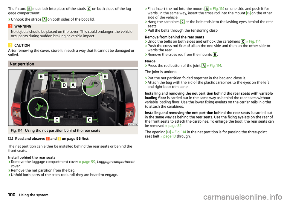
The fixture B must lock into place of the studs C on both sides of the lug-
gage compartment.›
Unhook the straps
A
on both sides of the boot lid.
WARNINGNo objects should be placed on the cover. This could endanger the vehicle
occupants during sudden braking or vehicle impact.
CAUTION
After removing the cover, store it in such a way that it cannot be damaged or
soiled.
Net partition
Fig. 114
Using the net partition behind the rear seats
Read and observe
and on page 96 first.
The net partition can either be installed behind the rear seats or behind the front seats.
Install behind the rear seats
›
Remove the luggage compartment cover » page 99, Luggage compartment
cover .
›
Remove the net partition from the bag.
›
Unfold both parts of the cross rod until they are heard to engage.
›First insert the rod into the mount B
» Fig. 114 on one side and push it for-
wards. In the same way, insert the cross rod into the mount B on the other
side of the vehicle.›
Hang the carabines
C
at the belt ends into the lashing eyes behind the rear
seats.
›
Pull the belts through the tensioning clasp.
Remove from behind the rear seats
›
Undo the belts on both sides and unhook the carabiners
C
» Fig. 114 .
›
Push the cross rod first of all on the one side and then on the other side to-
wards the rear.
›
Remove the cross rod from the mounts
B
.
Merge
›
Press the red button of the joint
A
» Fig. 114 .
The joint is undone.
›
Put the net partition folded together in the bag and close it.
›
Attach the bag with the aid of the plastic carabines to the eyes on the left
and right boot trim panel.
Installing and removing the net partition behind the rear seats with variable
loading floor is carried out in the same way as behind the rear seats without
variable loading floor. Use the lower fixing eyelets on the carrier rails in order
to attach the carabines.
Installing and removing the net partition behind the rear seats is carried out
in the same way as behind the rear seats. Use the fixing eyelets on the rear of
the front seats to attach the carabines. To enlarge the boot, the rear seats can
be removed » page 82.
The opening
D
» Fig. 114 in the net partition is for passing the three-point
seat belt » page 13 through.
100Using the system