warning light SKODA YETI 2015 1.G / 5L Service Manual
[x] Cancel search | Manufacturer: SKODA, Model Year: 2015, Model line: YETI, Model: SKODA YETI 2015 1.G / 5LPages: 232, PDF Size: 30.84 MB
Page 88 of 232
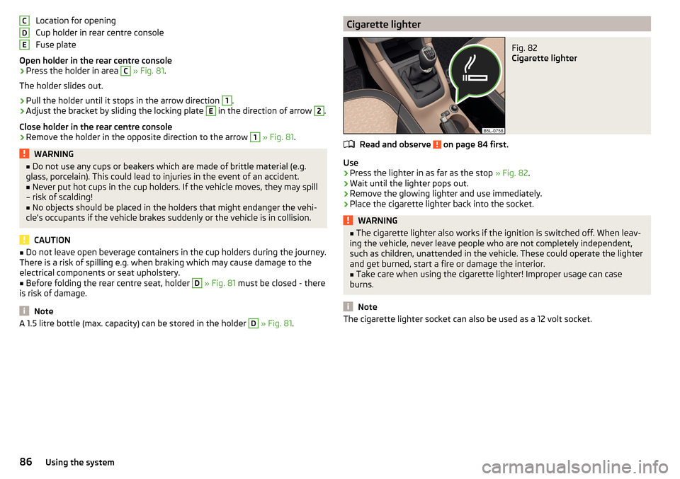
Location for opening
Cup holder in rear centre console
Fuse plate
Open holder in the rear centre console›
Press the holder in area
C
» Fig. 81 .
The holder slides out.
›
Pull the holder until it stops in the arrow direction
1
.
›
Adjust the bracket by sliding the locking plate
E
in the direction of arrow
2
.
Close holder in the rear centre console
›
Remove the holder in the opposite direction to the arrow
1
» Fig. 81 .
WARNING■
Do not use any cups or beakers which are made of brittle material (e.g.
glass, porcelain). This could lead to injuries in the event of an accident.■
Never put hot cups in the cup holders. If the vehicle moves, they may spill
– risk of scalding!
■
No objects should be placed in the holders that might endanger the vehi-
cle's occupants if the vehicle brakes suddenly or the vehicle is in collision.
CAUTION
■ Do not leave open beverage containers in the cup holders during the journey.
There is a risk of spilling e.g. when braking which may cause damage to the
electrical components or seat upholstery.■
Before folding the rear centre seat, holder
D
» Fig. 81 must be closed - there
is risk of damage.
Note
A 1.5 litre bottle (max. capacity) can be stored in the holder D » Fig. 81 .CDECigarette lighterFig. 82
Cigarette lighter
Read and observe on page 84 first.
Use
›
Press the lighter in as far as the stop
» Fig. 82.
›
Wait until the lighter pops out.
›
Remove the glowing lighter and use immediately.
›
Place the cigarette lighter back into the socket.
WARNING■
The cigarette lighter also works if the ignition is switched off. When leav-
ing the vehicle, never leave people who are not completely independent,
such as children, unattended in the vehicle. These could operate the lighter
and get burned, start a fire or damage the interior.■
Take care when using the cigarette lighter! Improper usage can case
burns.
Note
The cigarette lighter socket can also be used as a 12 volt socket.86Using the system
Page 98 of 232
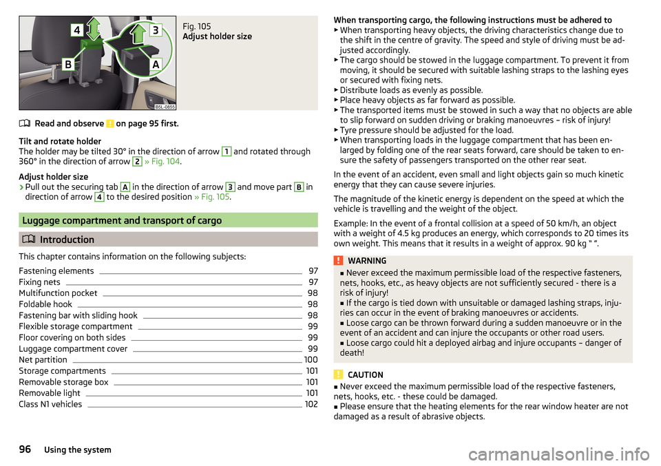
Fig. 105
Adjust holder size
Read and observe on page 95 first.
Tilt and rotate holder
The holder may be tilted 30° in the direction of arrow
1
and rotated through
360° in the direction of arrow
2
» Fig. 104 .
Adjust holder size
›
Pull out the securing tab
A
in the direction of arrow
3
and move part
B
in
direction of arrow
4
to the desired position » Fig. 105.
Luggage compartment and transport of cargo
Introduction
This chapter contains information on the following subjects:
Fastening elements
97
Fixing nets
97
Multifunction pocket
98
Foldable hook
98
Fastening bar with sliding hook
98
Flexible storage compartment
99
Floor covering on both sides
99
Luggage compartment cover
99
Net partition
100
Storage compartments
101
Removable storage box
101
Removable light
101
Class N1 vehicles
102When transporting cargo, the following instructions must be adhered to ▶ When transporting heavy objects, the driving characteristics change due to
the shift in the centre of gravity. The speed and style of driving must be ad-
justed accordingly.
▶ The cargo should be stowed in the luggage compartment. To prevent it from
moving, it should be secured with suitable lashing straps to the lashing eyes
or secured with fixing nets.
▶ Distribute loads as evenly as possible.
▶ Place heavy objects as far forward as possible.
▶ The transported items must be stowed in such a way that no objects are able
to slip forward on sudden driving or braking manoeuvres – risk of injury!
▶ Tyre pressure should be adjusted for the load.
▶ When transporting loads in the luggage compartment that has been en-
larged by folding one of the rear seats forward, care should be taken to en-
sure the safety of passengers transported on the other rear seat.
In the event of an accident, even small and light objects gain so much kinetic
energy that they can cause severe injuries.
The magnitude of the kinetic energy is dependent on the speed at which the
vehicle is travelling and the weight of the object.
Example: In the event of a frontal collision at a speed of 50 km/h, an object
with a weight of 4.5 kg produces an energy, which corresponds to 20 times its
own weight. This means that it results in a weight of approx. 90 kg “ ”.WARNING■ Never exceed the maximum permissible load of the respective fasteners,
nets, hooks, etc., as heavy objects are not sufficiently secured - there is a
risk of injury!■
If the cargo is tied down with unsuitable or damaged lashing straps, inju-
ries can occur in the event of braking manoeuvres or accidents.
■
Loose cargo can be thrown forward during a sudden manoeuvre or in the
event of an accident and can injure the occupants or other road users.
■
Loose cargo could hit a deployed airbag and injure occupants – danger of
death!
CAUTION
■ Never exceed the maximum permissible load of the respective fasteners,
nets, hooks, etc. - these could be damaged.■
Please ensure that the heating elements for the rear window heater are not
damaged as a result of abrasive objects.
96Using the system
Page 103 of 232
Storage compartmentsFig. 115
Storage compartment on the left / right
Read and observe
and on page 96 first.
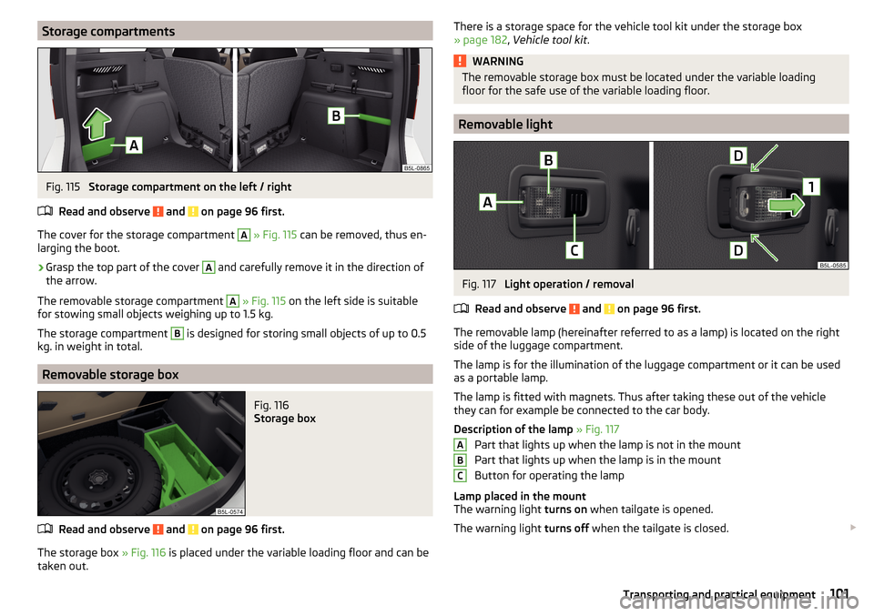
The cover for the storage compartment
A
» Fig. 115 can be removed, thus en-
larging the boot.
›
Grasp the top part of the cover
A
and carefully remove it in the direction of
the arrow.
The removable storage compartment
A
» Fig. 115 on the left side is suitable
for stowing small objects weighing up to 1.5 kg.
The storage compartment
B
is designed for storing small objects of up to 0.5
kg. in weight in total.
Removable storage box
Fig. 116
Storage box
Read and observe and on page 96 first.
The storage box » Fig. 116 is placed under the variable loading floor and can be
taken out.
There is a storage space for the vehicle tool kit under the storage box » page 182 , Vehicle tool kit .WARNINGThe removable storage box must be located under the variable loading
floor for the safe use of the variable loading floor.
Removable light
Fig. 117
Light operation / removal
Read and observe
and on page 96 first.
The removable lamp (hereinafter referred to as a lamp) is located on the right side of the luggage compartment.
The lamp is for the illumination of the luggage compartment or it can be used
as a portable lamp.
The lamp is fitted with magnets. Thus after taking these out of the vehicle
they can for example be connected to the car body.
Description of the lamp » Fig. 117
Part that lights up when the lamp is not in the mount
Part that lights up when the lamp is in the mount
Button for operating the lamp
Lamp placed in the mount
The warning light turns on when tailgate is opened.
The warning light turns off when the tailgate is closed.
ABC101Transporting and practical equipment
Page 107 of 232
WARNING■For your own safety and that of other road users, ensure that all the win-
dows are free of ice, snow and misting. The blower should always be on to
prevent the windows from misting up.■
Under certain circumstances, air at a temperature of about 5 °C can flow
out of the vents when the cooling system is switched on.
CAUTION
■ The air inlet in front of the windscreen must be free of e.g. ice, snow or
leaves to ensure that the heating and cooling system operates properly.■
After switching on the cooling Condensation from the evaporator of the air
conditioning may drip down and form a puddle below the vehicle. This is not a
leak!
■
If the coolant temperature is too high, the cooling system is switched off to
ensure that the engine cools down.
Heating and manual air conditioning
Fig. 122
Heating Controls
Fig. 123
Controls of the manual air conditioning
Read and observe
and on page 105 first.
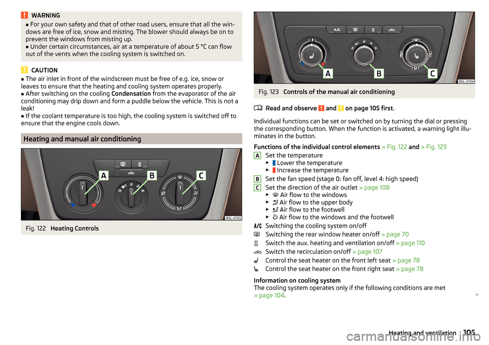
Individual functions can be set or switched on by turning the dial or pressing the corresponding button. When the function is activated, a warning light illu-
minates in the button.
Functions of the individual control elements » Fig. 122 and » Fig. 123
Set the temperature
▶ Lower the temperature
▶ Increase the temperature
Set the fan speed (stage 0: fan off, level 4: high speed)
Set the direction of the air outlet » page 108
▶ Air flow to the windows
▶ Air flow to the upper body
▶ Air flow to the footwell
▶ Air flow to the windows and the footwell
Switching the cooling system on/off
Switching the rear window heater on/off » page 70
Switch the aux. heating and ventilation on/off » page 110
Switch the recirculation on/off » page 107
Control the seat heater on the front left seat » page 78
Control the seat heater on the front right seat » page 78
Information on cooling system
The cooling system operates only if the following conditions are met
» page 104 .
ABC105Heating and ventilation
Page 108 of 232
The warning light in the button » Fig. 123 illuminates after activation, even
if not all of the conditions for the function of the cooling system have been
met. By lighting up of the indicator light in the button, the operational readi-
ness of the cooling system is signalled.
Note
During operation of the manual air conditioning, an increase in engine idle
speed may occur under certain circumstances in order to ensure sufficient
heating comfort.
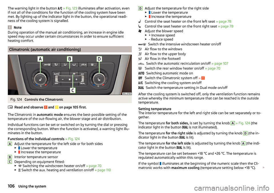
Climatronic (automatic air conditioning)
Fig. 124
Controls the Climatronic
Read and observe
and on page 105 first.
The Climatronic in automatic mode ensures the best-possible setting of the
temperature of the out-flowing air, the blower stage and air distribution.
Individual functions can be set or switched on by turning the dial or pressing
the corresponding button. When the function is activated, a warning light illu-
minates in the button.
Functions of the individual controls » Fig. 124
Adjust the temperature for the left side or for both sides
▶ Lower the temperature
▶ Increase the temperature
Interior temperature sensor
Depending on equipment fitted:
▶ Switching the windscreen heater on/off
» page 70
▶ Switch the aux. heating and ventilation on/off
» page 110
ABCAdjust the temperature for the right side
▶ Lower the temperature
▶ Increase the temperature
Control the seat heater on the front left seat » page 78
Control the seat heater on the front right seat » page 78
Adjust the blower speed ▶ + Increase speed
▶ - Reduce speed
Switch the intensive windscreen heater on/off
Air flow to the windows
Air flow to the upper body
Air flow in the footwell Switch the automatic recirculation on/off » page 107
Switch the rear window heater on/off » page 70
Switching automatic mode on
Switch the Climatronic system off »
Switching the cooling system on/off
Switch the temperature setting in Dual mode on/off
After the cooling system is switched off, only the ventilation function remains
active whereby the minimum temperature that can be reached is the outside
temperature.
Setting temperature
The interior temperature for the left and right side can be set separately or to-
gether.
The temperature for both sides, is set by turning the knob
A
» Fig. 124 (the
indicator light in the button is not illuminated).
The temperature for the right side is adjusted by turning the knob
D
(the in-
dicator light in the button is lit).
The temperature for the left side is adjusted by turning the knob
A
(the indi-
cator light in the button is lit).
The temperature can be set between +18 °C and +26 °C. The temperature is
regulated automatically within this range.
If the symbol illuminates at the beginning of the numeric scale then the Cli-
matronic works with maximum cooling (temperature setting below +18 °C).
D106Using the system
Page 109 of 232
If the symbol illuminates at the end of the numeric scale then the Climatronic
works with maximum heating (temperature setting above +26 °C).
There is no automatic temperature control in the two end positions.
Controlling blower
The Climatronic system controls the blower stages automatically in line with the interior temperature. However, the blower stages can be manually adap-
ted to suit your particular needs.
If the blower speed is reduced to a minimum, Climatronic is switched off.
The set blower speed is displayed above the symbol button
when the re-
spective number of indicator lights come on.WARNING■ Do not switch off the Climatronic system for longer than necessary.■Switch on the Climatronic system as soon as the windows mist up.
CAUTION
Do not cover the interior temperature sensor B » Fig. 124 as this could impair
the functioning of the Climatronic.
Note
■ If the windscreen mists up, press the symbol button . Press the button
once the windscreen has demisted.■
During operation of the Climatronic, an increase in engine idle speed can oc-
cur under certain circumstances in order to ensure adequate heating comfort.
Climatronic - automatic operation
Read and observe
and on page 105 first.
The automatic mode is used in order to maintain a constant temperature andto demist the windows in the interior of the car.
If the warning light in the top right corner of the button lights up, the Cli-
matronic operates in “HIGH”-mode.
Upon pressing the button again, the Climatronic switches to “LOW”-mode
and the indicator light in the top left corner lights up. The Climatronic uses on-
ly in this mode the lower blower speed. However taking into account the noise
level, this is more comfortable, yet be aware that the effectiveness of the air
conditioning system is reduced particularly if the vehicle is fully occupied.
By pressing the button again, it is changed to “HIGH”-mode.
Automatic mode can be switched off by pressing one of the buttons for the air
distribution or by increasing/decreasing the blower speed. The temperature
regulation is continued.
Note
Climatronic is set to the “HIGH” mode at the factory.
Air distribution control
Read and observe
and on page 105 first.
The recirculation mode prevents contaminated outside air getting into the in-
terior of the vehicle.
In recirculated air mode air is sucked out of the interior of the vehicle and then
fed back into the interior.
Heating and manual air conditioning system
›
To turn the recirculation mode on or off, press the Symbol key
.
The air recirculation mode is automatically turned off by turning the air distri-
bution control
C
to position
» Fig. 122 on page 105 or » Fig. 123 on
page 105 .
Recirculated air mode can be switched on again from this position by repeat-
edly pressing the symbol button .
Climatronic (automatic air conditioning)
›
To turn the recirculation mode on, press the Symbol key
repeatedly until
the indicator light is lit on the left side of the button.
›
To activate the automatic recirculation mode, press the Symbol key
re-
peatedly until the indicator light is lit on the right side of the button.
Climatronic has an air quality sensor for the detection of the pollutant concen-
tration in the sucked-in air.
If a considerable increase in concentration of pollutants is recognised by the
air quality sensor, recirculated air mode will temporarily be switched on.
If the concentration of pollutants decreases to the normal level, the air distri-
bution control is automatically switched off so that fresh air can be guided into
the vehicle interior.
107Heating and ventilation
Page 110 of 232
If the air quality sensor does not automatically switch on the recirculated air
mode in the event of an unpleasant odour, you can switch it on yourself by
pressing the button . The indicator light lights up in the button on the left
side.
To turn off the air recirculation or to deactivate the automatic air recircula-
tion , press the
button of press the symbol button repeatedly until the
warning lights in the button go out.WARNINGThe recirculation system cannot be switched on for a longer period of time,
because there is no supply of fresh air from the outside. “Stale air” may re-
sult in fatigue in the driver and occupants, reduce attention levels and also
cause the windows to mist up. The risk of having an accident increases.
Switch off recirculated air mode as soon as the windows start to mist up.
CAUTION
We recommend not smoking in the vehicle when the recirculating air operation
is switched on. The smoke sucked from inside the vehicle is deposited on the
evaporator of the air conditioner. This produces a permanent odour when the
air conditioning system is operating which can only be eliminated through con-
siderable effort and expense (replacement of compressor).
Note
The automatic air distribution control operates only if the outside temperature
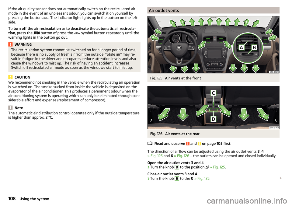
is higher than approx. 2 °C.Air outlet ventsFig. 125
Air vents at the front
Fig. 126
Air vents at the rear
Read and observe
and on page 105 first.
The direction of airflow can be adjusted using the air outlet vents 3, 4
» Fig. 125 and 6 » Fig. 126 – the outlets can be opened and closed individually.
Open the air outlet vents 3 and 4
›
Turn the knob
B
to the position
» Fig. 125 .
Close air outlet vents 3 and 4
›
Turn the knob
B
to the 0 » Fig. 125 .
108Using the system
Page 111 of 232
Open the air outlet vents 6›Turn the knob C between the end positions » Fig. 126.
Close air outlet vents 6›
Turn the knob
C
to the end position » Fig. 126.
Change air flow of air outlet vents 3 and 4
›
To change the height of the air flow, swivel the horizontal fins with the mov-
able adjuster elements
A
upward or downward » Fig. 125.
›
To adjust the lateral direction of the air flow, turn the vertical fins with the
movable adjuster element
A
to the left or to the right.
Change air flow of air outlet vents 6
›
To change the height of the air flow, swivel the horizontal fins with the verti-
cal adjuster elements
C
upward or downward » Fig. 126.
›
To adjust the lateral direction of the air flow, turn the vertical fins with the
horizontal movable adjuster element
D
to the left or to the right.
An overview of the available settings for adjusting the direction of the air
outlet
Set the direction of the air outletActive air outlet nozzles » Fig. 125 and
» Fig. 126 1. 2 . 41. 2 . 4 . 5 . 7 3. 4 . 64 . 5 . 7
CAUTION
To ensure that the heating, the manual air conditioning and the Climatronic
systems work properly, do not block up the air outlet vents with any objects.
Note
The air outlet vents 6 » Fig. 126 are only fitted on vehicles with the higher cen-
tre console.Auxiliary heating (auxiliary heating and ventilation)
Introduction
This chapter contains information on the following subjects:
Switching on and off directly
110
System settings
110
Radio remote control
111
Functional requirements of the auxiliary heating (aux. heating and ventilation) The charge state of the vehicle battery is sufficient.
The fuel supply is adequate (the warning light is not illuminated in the
instrument cluster).
Aux. heating
The auxiliary heating can be used when both when stationary, when the en-
gine is switched off, to preheat the vehicle and also while driving (e.g. during
the heating phase of the engine).
The auxiliary heating warms up the coolant by combusting fuel from the vehi-
cle tank. This heats the air flowing into the passenger compartment (if the
blower is turned on).
The auxiliary heating also warms up the engine.
The heater is switched on or off automatically depending on the ambient con-
ditions to give the best possible conditions for the engine running and the in-
terior heating.
For vehicles with gasoline engines, the automatic switching on and off of the
heater can be disabled in a specialist workshop.
Auxiliary ventilation
The auxiliary ventilation enables fresh air to flow into the vehicle interior by
switching off the engine, whereby the interior temperature is effectively de-
creased (e.g. with the vehicle parked in the sun).
109Heating and ventilation
Page 113 of 232
■Deactivate - Deactivate pre-set mode
■Factory setting.
- Restore factory setting
■
Back
- return to main menu.
Only one programmed pre-set time can be active.
The last programmed pre-set time remains active.
After the auxiliary heating activates at the set time, it is necessary to pre-set a time again.
If the pre-set menu is closed by selecting the
Back
menu item or if no changes
are made on the display for more than 10 seconds, the set values are stored,
but the pre-set time is not activated.
An indicator light on the button is illuminated when the system is running.
The running system deactivates after expiration of the operating period or can
be deactivated earlier by pressing the button to directly switch on/off the aux-
iliary heating or by using the radio remote control.
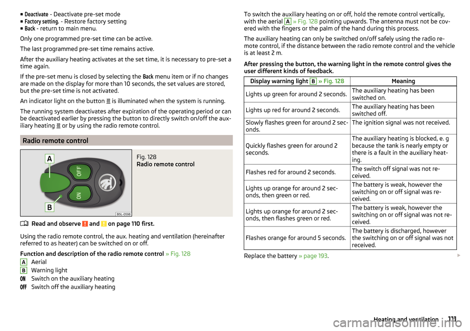
Radio remote control
Fig. 128
Radio remote control
Read and observe and on page 110 first.
Using the radio remote control, the aux. heating and ventilation (hereinafter
referred to as heater) can be switched on or off.
Function and description of the radio remote control » Fig. 128
Aerial
Warning light
Switch on the auxiliary heating
Switch off the auxiliary heating
ABTo switch the auxiliary heating on or off, hold the remote control vertically,
with the aerial A » Fig. 128 pointing upwards. The antenna must not be cov-
ered with the fingers or the palm of the hand during this process.
The auxiliary heating can only be switched on/off safely using the radio re-
mote control, if the distance between the radio remote control and the vehicle
is at least 2 m.
After pressing the button, the warning light in the remote control gives the
user different kinds of feedback.Display warning light B » Fig. 128MeaningLights up green for around 2 seconds.The auxiliary heating has been
switched on.Lights up red for around 2 seconds.The auxiliary heating has been
switched off.Slowly flashes green for around 2 sec-
onds.The ignition signal was not received.Quickly flashes green for around 2
seconds.The auxiliary heating is blocked, e. g
because the tank is nearly empty or
there is a fault in the auxiliary heat-
ing.Flashes red for around 2 seconds.The switch off signal was not re-
ceived.Lights up orange for around 2 sec-
onds, then green or red.The battery is weak, however the
switching on or off signal was re-
ceived.Lights up orange for around 2 sec-
onds, then flashes green or red.The battery is weak, however the
switching on or off signal was not re-
ceived.Flashes orange for around 5 seconds.The battery is discharged, however
the switching on or off signal was not
received.
Replace the battery » page 193.
111Heating and ventilation
Page 116 of 232
Steering lock locking / unlockingRead and observe
and on page 113 first.
The steering lock (steering lock) deters any attempted theft of your vehicle.
Locking
›
Withdraw the ignition key.
›
Turn the steering wheel to the left or right until the steering lock clicks into
place.
Unlocking
›
Insert the key into the ignition lock.
›
Switch on the ignition » page 114.
The steering wheel is unlocked.
If the ignition switch cannot be turned on, then turn the steering wheel back
and forth slightly and thereby unlock the steering lock.
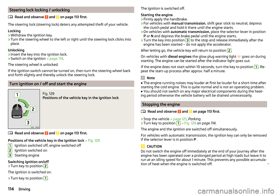
Turn ignition on / off and start the engine
Fig. 129
Positions of the vehicle key in the ignition lock
Read and observe and on page 113 first.
Positions of the vehicle key in the ignition lock » Fig. 129
Ignition switched off, engine switched off
Ignition switched on
Starting engine
Switching ignition on/off
›
Turn key to position
2
.
The ignition is switched on.
›
Turn key to position
1
.
123The ignition is switched off.
Starting the engine›
Firmly apply the handbrake.
›
For vehicles with manual transmission , shift gear stick to neutral, depress
the clutch pedal and hold it there until the engine starts.
›
On vehicles with automatic transmission , place the selector lever in position
P or N and depress the brake pedal until the engine starts.
›
Turn the key into position
3
to the stop and release immediately after the
engine has been started – do not apply the accelerator.
After letting go, the vehicle key will return to position
2
.
On vehicles with diesel engines the glow plug warning light
goes on during
starting. The engine can be started after the indicator light goes out.
If the engine does not start within 10 seconds, turn the key to position
1
. Re-
peat the start-up process after approx. half a minute.
Note
■ The engine running noises may louder at first be louder for a short time after
starting the cold engine. This is quite normal and is not an operating problem.■
You should not switch on any major electrical components during the heat-
ing period otherwise the vehicle battery will be drained unnecessarily.
Stopping the engine
Read and observe
and on page 113 first.
›
Stop the vehicle » page 121, Parking .
›
Turn key to position
1
» Fig. 129 on page 114 .
The engine and the ignition are switched off simultaneously.
For vehicles with automatic transmission, the ignition key can only be removed
if the selector lever is in position P .
CAUTION
Do not switch the engine off immediately at the end of your journey after the
engine has been operated over a prolonged period at high loads but leave it to
run at an idling speed for about 1 minute. This prevents any possible accumula-
tion of heat when the engine is switched off. 114Driving