four wheel drive SKODA YETI 2015 1.G / 5L Owner's Manual
[x] Cancel search | Manufacturer: SKODA, Model Year: 2015, Model line: YETI, Model: SKODA YETI 2015 1.G / 5LPages: 232, PDF Size: 30.84 MB
Page 14 of 232
WARNING (Continued)■Check the condition of all the seat belts on a regular basis. If any damage
to the seat belts, seat belt connections, inertia reel or the lock is detected,
the relevant seat belt must be replaced by a specialist garage.■
Damaged seat belts which have been subjected to stress in an accident
and were therefore stretched, must be replaced – this is best done by a
specialist garage. The anchorage points of the belts must also be inspec-
ted. The anchorage points for the belts should also be checked.
The physical principle of a head-on collision
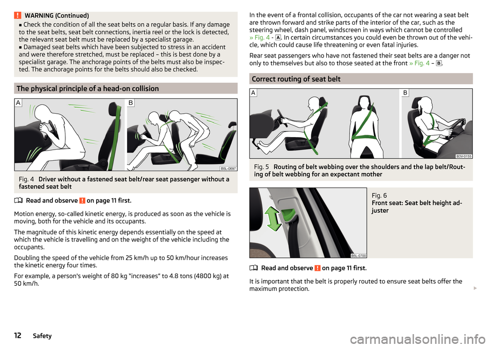
Fig. 4
Driver without a fastened seat belt/rear seat passenger without a
fastened seat belt
Read and observe
on page 11 first.
Motion energy, so-called kinetic energy, is produced as soon as the vehicle is
moving, both for the vehicle and its occupants.
The magnitude of this kinetic energy depends essentially on the speed at
which the vehicle is travelling and on the weight of the vehicle including the
occupants.
Doubling the speed of the vehicle from 25 km/h up to 50 km/hour increases the kinetic energy four times.
For example, a person's weight of 80 kg “increases” to 4.8 tons (4800 kg) at
50 km/h.
In the event of a frontal collision, occupants of the car not wearing a seat belt
are thrown forward and strike parts of the interior of the car, such as the
steering wheel, dash panel, windscreen in ways which cannot be controlled
» Fig. 4 -
. In certain circumstances you could even be thrown out of the vehi-
cle, which could cause life threatening or even fatal injuries.
Rear seat passengers who have not fastened their seat belts are a danger not only to themselves but also to those seated at the front » Fig. 4 –
.
Correct routing of seat belt
Fig. 5
Routing of belt webbing over the shoulders and the lap belt/Rout-
ing of belt webbing for an expectant mother
Fig. 6
Front seat: Seat belt height ad-
juster
Read and observe on page 11 first.
It is important that the belt is properly routed to ensure seat belts offer the
maximum protection.
12Safety
Page 43 of 232
Gear recommendation - segment display
The recommended 1)
gear and the arrow icon is displayed.
▶ - Recommends that you change up to a higher gear
▶ - Recommends that you change down to a lower gear
If the display shows for example
in vehicles with a manual gearbox, this
means it is better to switch from a lower gear to the fourth gear.
If for example
is shown in the display in vehicles with an automatic gearbox
which is in manual switching mode (Tiptronic), it is better to switch from the
fourth gear to a higher gear.WARNINGThe driver is always responsible for selecting the correct gear in different
driving situations, such as overtaking.
Multifunction display (MFD)
Introduction
This chapter contains information on the following subjects:
Operation
41
Information overview
42
Warning when exceeding the set speed
42
Memory
43
The driving data is displayed on the multifunction display.
The multifunction display only operates if the ignition is switched on. After the ignition is switched on, the function that was last selected before switching
off the ignition is displayed.
For vehicles with a MAXI DOT display, the menu item
MFD
must be selected and
confirmed in the main menu » page 43, MAXI DOT display .
On vehicles with a MAXI DOT display, there is an option to fade out some of
the information » page 47, Menu item
Settings
.
WARNINGConcentrate fully at all times on your driving! As the driver, you are fully re-
sponsible for the operation of your vehicle.
Note
If the display of the second speed is activated in mph, the current speed is not
indicated in km/h on the display.
Operation
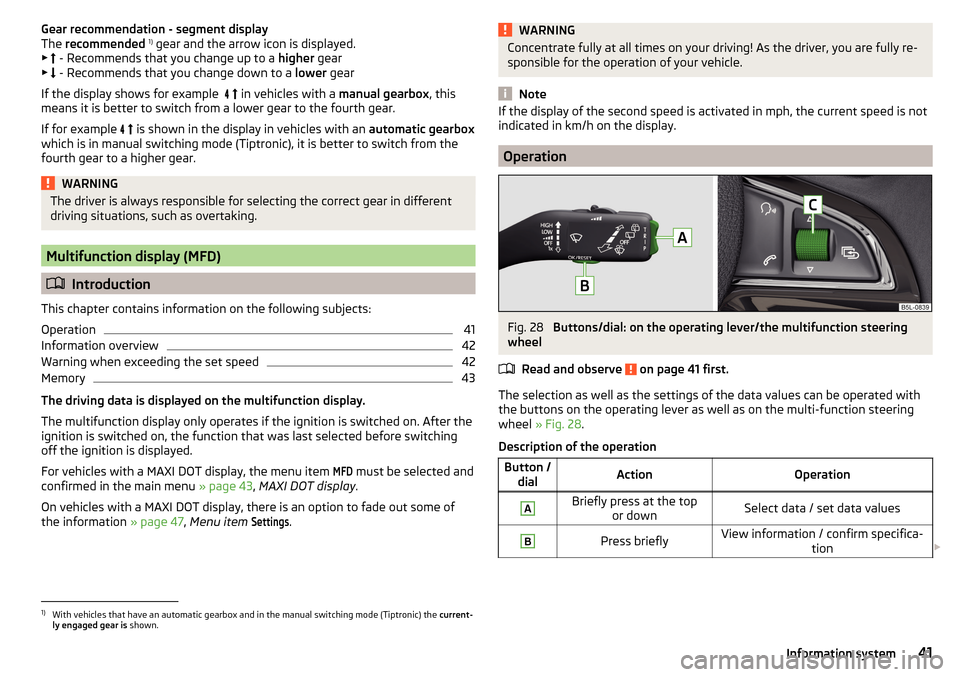
Fig. 28
Buttons/dial: on the operating lever/the multifunction steering
wheel
Read and observe
on page 41 first.
The selection as well as the settings of the data values can be operated with
the buttons on the operating lever as well as on the multi-function steering
wheel » Fig. 28 .
Description of the operation
Button / dialActionOperationABriefly press at the top or downSelect data / set data valuesBPress brieflyView information / confirm specifica- tion 1)
With vehicles that have an automatic gearbox and in the manual switching mode (Tiptronic) the
current-
ly engaged gear is shown.
41Information system
Page 131 of 232
The HHC is active from a 5% slope if the driver's door is closed. HHC is only ev-
er active on slopes when in forward or reverse start off.
Trailer stabilization system (TSA)
Read and observe
on page 127 first.
The TSA helps the combination stable in situations where the trailer sways
and then the whole trailer combination.
TSA brakes the individual wheels of the towing vehicle in order to damp the
rocking motion of the entire vehicle combination.
The following conditions are required for the correct TSA function. The trailer was shipped from the factory or purchased from the ŠKODA
genuine accessories.
The trailer is electrically connected to the towing vehicle via the trailer
socket.
The TCS is activated.
The speed is higher than approx. 60 km/h.
Further information » page 141, Hitch and trailer .
OFF ROAD-mode
Introduction
This chapter contains information on the following subjects:
Operation
129
Hill Descent Assistant
130
TCSOFF ROAD
130
EDS OFF ROAD
130
ABS OFF ROAD
130
Start-Off Assistant
131
The OFF ROAD mode includes several features that help to overcome difficult
navigable routes when travelling on non-paved roads.
But even with OFF ROAD mode activated, your vehicle is never a true SUV.
WARNING■ The general information relating to the use of assistance systems must
be observed » page 127, in section Introduction .■
A lack of fuel can cause irregular engine running or cause the engine to
shut down. This would lead the OFF ROAD mode to lose its effectiveness -
risk of accident!
CAUTION
■ The OFF ROAD mode is not designed for the use on common roads.■All four wheels must be fitted with the same tyres approved by the manufac-
turer to ensure theOFF ROAD mode operates correctly.
Operation
Fig. 142
OFF ROAD button
Read and observe and on page 129 first.
We recommend that you activate the OFF ROAD mode for every trip on non- paved roads.
Activating
›
Press the symbol button
» Fig. 142 .
The symbol in the button comes on.
Deactivate
›
Press the symbol key
» Fig. 142 or turn the ignition off.
The symbol in the button is no longer illuminated.
129Assist systems
Page 143 of 232
Save tyre pressure valuesFig. 152
Key for storing the pressure val-
ues
Read and observe on page 140 first.
Procedure for storing the tyre pressure values
›
Inflate all the tyres to the specified pressure.
›
Switch on the ignition.
›
Press
» Fig. 152 and hold it down.
The warning light in the instrument cluster lights up.
An acoustic signal and the control indicator provide information about the
storage of the tyre pressure values.
›
Release the Release the symbol key.
Always save the tyre pressure values in the system if one of the following
events occurs.
▶ Change of tyre inflation pressure.
▶ Change one or more wheels.
▶ Change in position of a wheel on the vehicle.
▶ Illumination of the warning light in the instrument cluster.
WARNINGBefore storing the pressures, the tyres must be inflated to the specified in-
flation pressure » page 176. If the wrong pressure valuesare stored, the
system may not issue any warnings, even if the tyre pressure is too low.
CAUTION
Save the tyre pressure values every 10,000 km or 1x annually to ensure correct
system functioning.Hitch and trailer
Hitch
Introduction
This chapter contains information on the following subjects:
Description
142
Adjusting the ready position
142
Correctly set ready position
143
Installing the ball rod
143
Check proper fitting
144
Removing the ball rod
144
Mount accessories
145
The maximum trailer drawbar load is 80 kg/h.
On vehicles with four-wheel drive and the 2.0 l / 103 kW TDI CR or 2.0 L /
110 kW TDI CR engine, the maximum trailer nose weight is 85 kg .
The draw bar load information on the type plate of the towing device is merely
a test value for the towing device. The vehicle-specific information is detailed
in the vehicle documents.
WARNING■ Check that the tow bar is seated correctly and is secured in the mounting
recess before the start of every journey.■
Do not use the ball head, if it is not correctly inserted into the mounting
recess and secured.
■
Do not use the towing equipment if it is damaged or incomplete.
■
Do not modify or adapt the towing device in any way.
■
Keep the mounting recess of the towing equipment clean at all times.
Such dirt prevents the ball head from being attached securely.
CAUTION
■ Take care with the ball bar - risk of paint damage to the bumper.■Always attach the cap to the receiving shaft when the ball bar is removed -
risk of receiving-shaft contamination. 141Hitch and trailer
Page 163 of 232
Vehicles without lockable fuel filler flap›Press on the fuel filler flap in the direction of the arrow 1 accordingly
» Fig. 163 .›
Open the cover in the direction of the arrow
2
.
›
Hold the filler cap and unlock by turning the key in the direction of the arrow
3
.
›
Unscrew the tank cap in the direction of the arrow
3
.
›
Remove the tank cap and place on top of the fuel filler flap in direction of ar-
row
4
.
›
Insert the pump nozzle into the fuel filler tube as far as it will go.
The fuel tank is full just as soon as the pump nozzle switches off for the first
time »
.
›
Remove the pump nozzle from the fuel filler neck and put it back in the
pump.
›
Screw in the tank cap in the opposite direction of the arrow
3
until it audibly
clicks into place.
›
Hold the filler cap and lock it by turning in the opposite direction of the arrow
3
. Remove the key.
›
Close the fuel filler flap until it clicks into place.
Check that the fuel filler flap is closed properly.
WARNINGInstructions for filling the reserve canister■Never fill the reserve can inside the vehicle.■
Never place the reserve can on the vehicle.
■
Always place the reserve can on the floor.
■
We do not recommend carrying any fuel canisters in your vehicle for safe-
ty reasons. in the event of an accident, these canisters can become dam-
aged and fuel may escape – risk of fire!
CAUTION
■ The fuel tank is full just as soon as the pump nozzle switches off for the first
time, provided the nozzle has been operated properly. Not continue refuelling.■
Be careful when filling diesel fuel from the spare canister and then do this
slowly and cautiously – danger of contaminating the body.
NoteThe fuel capacity for vehicles with front wheel drive is about 55 litres, and for
vehicles with four-wheel drive about 60 litres, with about 9 litres as reserve.
Lead-free petrol
The correct fuel grades for your vehicle are specified on the inside of the fuel
filler flap.
Read and observe
and on page 160 first.
The vehicle can only be operated with unleaded petrol in compliance with the
EN 228 1)
standard.
All petrol engines can be operated using petrol that contains at most 10% bio-
ethanol (E10).
Unleaded petrol 95/91 or 92 or 93 RON/ROZ
We recommend using unleaded fuel with an octane rating of 95 RON. Unlea-
ded petrol with the octane ratings 91, 92 or 93 RON can also be used, but may
result in a slight loss in performance and slightly increased fuel consumption.
Unleaded petrol min. 95 RON / ROZ
Use unleaded fuel with the octane rating 95 RON or higher.
In an emergency petrol with the octane ratings 91, 92 and/or 93 RON can also
be used, but may result in a slight loss in performance and slightly increased
fuel consumption and exhaust emissions. Continue driving at medium engine
speeds and minimum engine load »
.
Refuel using petrol of the prescribed octane number as soon as possible.
Unleaded petrol 98/(95) RON / ROZ
We recommend using unleaded fuel with an octane rating of 98 RON or higher.
Unleaded petrol 95 RON can also be used but this results in a slight loss in per-
formance and slightly increased fuel consumption.
In an emergency petrol with the octane ratings 91, 92 and/or 93 RON can also
be used, but may result in a slight loss in performance and slightly increased
fuel consumption and exhaust emissions. Continue driving at medium engine
speeds and minimum engine load »
.
Refuel using petrol of the prescribed octane number as soon as possible.
1)
In Germany also DIN 51626-1 or E10 for unleaded petrol with octane number 91 or 95 or DIN 51626-2 or E5
for unleaded petrol with octane number 95 and 98.
161Inspecting and replenishing
Page 181 of 232
In vehicles with tyre pressure monitoring, save tyre pressure values» page 141.WARNING■
If, you get a puncture and a spare tyre has to be mounted with opposite
direction of rotation, then drive carefully. The best properties of the tyre
are no longer present in this situation.■
If the dimensions or design of the spare wheel differ from the tyres fitted
to the vehicle (e.g. winter tyres or low-profile tyres), it must only be used
briefly in the event of a puncture and if an appropriately cautious style of
driving is adopted.
■
Never use the temporary spare wheel if it is damaged.
Spare wheel
Read and observe
on page 176 first.
A yellow warning label is always displayed on the rim of the temporary spare
wheel.
Please note the following if you intend to use the temporary spare wheel. ▶ The warning label must not be covered after installing the wheel.
▶ Be particularly observant when driving.
▶ The temporary spare wheel is inflated to the maximum inflation pressure for
the vehicle » page 176.
▶ Only use this temporary spare wheel to reach the nearest specialist garage,
since it is not intended for permanent use.
If you need to use a spare wheel, make sure to fit a standard wheel of the ap-
propriate dimensions and design as soon as possible.
In vehicles with tyre pressure monitoring, save tyre pressure values » page 141.
WARNING■
Never drive with more than one spare wheel mounted!■Only use the spare wheel while absolutely necessary.■
Avoid accelerating at full throttle, sharp braking and fast cornering.
■
The snow chains cannot be used on the spare wheel.
■
If the dimensions or design of the temporary spare wheel differ from the
tyres fitted, never drive faster than 80 km/h (or 50 mph).
■
Never use the emergency spare wheel if it is damaged.
■
Observe instructions on the warning sign of the emergency wheel.
Tyre label
Read and observe
on page 176 first.
Only use radial tyres of the same type, size (rolling circumference) and treadpattern on one axle on all four wheels.
When mounting new tires the tires have to be replaced axle by axle.
Explanation of tyre markings
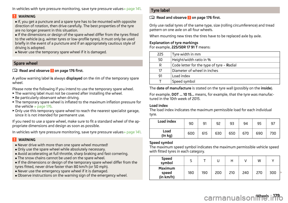
For example, 225/50R 17 91 T means:
225Tyre width in mm50Height/width ratio in %RCode letter for the type of tyre – Radial17Diameter of wheel in inches91Load indexTSpeed symbol
The date of manufacture is stated on the tyre wall (possibly on the inside).
For example, DOT ... 10 15... means, for example, that the tyre was manufac-
tured in the 10th week of 2015.
Load index
The load index indicates the maximum permissible load for each individual
tyre.
Load index90919293949597Load
(In kg)600615630650670690730
Speed symbol
The maximum speed symbol indicates the maximum permissible vehicle speed
with fitted tyres in each category.
Speed
symbolSTUHVWYMaximum speed
(in km/h)180190200210240270300
179Wheels
Page 182 of 232
WARNING■Never exceed the maximum permissible load bearing capacity of moun-
ted tyres.■
Never exceed the maximum permissible speed for the mounted tyres.
Winter operation
Introduction
This chapter contains information on the following subjects:
Winter tyres
180
Snow chains
180
Do not use alloy rims with bevelled or polished surfaces during the winter. The
rim surface does not have sufficient corrosion protection and could be perma-
nently damaged (e.g. through grit).
Winter tyres
The handling of your vehicle will be significantly improved when driving on
wintry roads if you fit winter tyres (labelled M+S).
To obtain the best possible handling, winter tyres must be fitted to all four
wheels. The minimum tread depth must be 4 mm.
Fit the summer tyres on again in good time as they provide better handling
properties, a shorter braking distance, less tyre noise, and reduced tyre wear
on roads which are free of snow and ice as well as at temperatures above 7 °C.
Speed symbol
Winter tyres (marked with M+S and a peak/snowflake symbol
) of a lower
speed category can be used provided that the permissible maximum speed of
these tyres is not exceeded even if the possible maximum speed of the vehicle
is higher.
The speed limit for winter tyres can be set in the MAXI DOT display in the
menu item
Winter tyres
» page 47 .
Snow chains
When driving in wintry road conditions, snow chains improve not only traction,
but also the braking performance.
The use of snow chains on vehicles with front-wheel drive and on vehicles
with four-wheel drive differs.
Front-wheel drive
Snow chains must only be mounted on the front wheels.
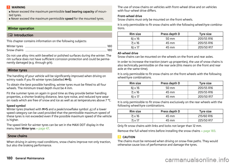
It is only permissible to fit snow chains with the following wheel/tyre combina-
tions.Rim sizePress depth DTyre size6J x 1650 mm205/55 R167J x 1645 mm205/55 R166J x 1745 mm205/50 R17
All-wheel drive
Snow chains can be mounted on the wheels on the front and rear axles.
In order to increase the traction (start-up properties), the use of snow chains is
also technically permissible on the rear axle (this means on the front and rear
axle at the same time).
It is only permissible to fit snow chains on the front wheels with the following
wheel/tyre combinations.
Rim sizePress depth DTyre size6J x 1650 mm205/55 R167J x 1645 mm205/55 R166J x 1745 mm205/50 R17
It is only permissible to fit snow chains exclusively on the rear wheels with the
following wheel/tyre combinations.
Rim sizePress depth DTyre size7J x 1645 mm215/60 R167J x 1745 mm225/50 R17
Only fit snow chains with links and locks not larger than 12 mm.
Remove the full wheel trims before installing the snow chains » page 183.
CAUTION
The chains must be removed when driving on snow-free paths. They would
otherwise cause loss of performance and damage the tyres.180General Maintenance