check engine SKODA YETI 2016 1.G / 5L User Guide
[x] Cancel search | Manufacturer: SKODA, Model Year: 2016, Model line: YETI, Model: SKODA YETI 2016 1.G / 5LPages: 200, PDF Size: 28.98 MB
Page 126 of 200
Towing device and trailer
Hitch
ï¤Introduction
This chapter contains information on the following subjects:
Description
124
Setting the ready position
125
Check the setting of the standby position
125
Assemble the ball rod
125
Check proper mounting
126
Removing ball rod - Step 1
126
Removing ball rod - Step 2
127
Vertical load with mounted accessories
127
The maximum trailer nose weight when towing a trailer is 80 kg, for vehicles
with four-wheel drive and the 2.0 l / 103 kW TDI CR or 2.0 l / 110 kW TDI CR
engine, it is 85 kg. Other information (e.g. on the nameplate of the trailer de-
vice) provide only about the test values of the device information.
WARNINGâ Check that the tow bar is seated correctly and is secured in the mounting
recess before the start of every journey.â
When the ball rod is not used and properly secured in the receiving shaft,
this could be damaged or incomplete and must not be used -There is a risk
of an accident.
â
Do not modify or adapt the towing device in any way.
â
Keep the mounting recess of the towing equipment clean at all times.
Such dirt prevents the ball head from being attached securely.
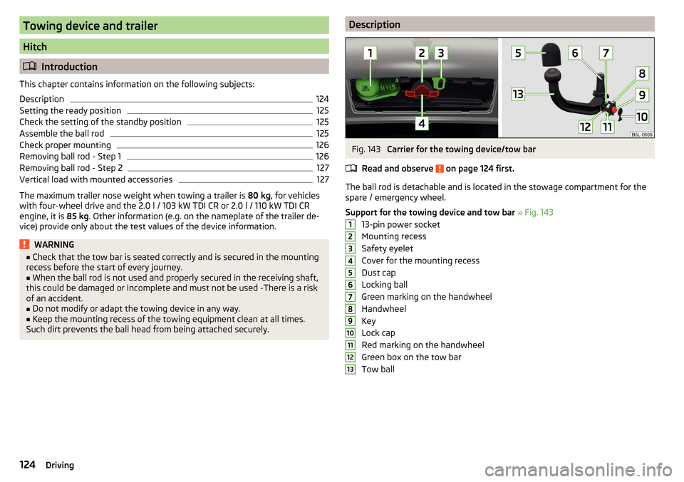
DescriptionFig. 143
Carrier for the towing device/tow bar
Read and observe
on page 124 first.
The ball rod is detachable and is located in the stowage compartment for the
spare / emergency wheel.
Support for the towing device and tow bar » Fig. 143
13-pin power socket
Mounting recess
Safety eyelet
Cover for the mounting recess
Dust cap
Locking ball
Green marking on the handwheel
Handwheel
Key
Lock cap
Red marking on the handwheel
Green box on the tow bar
Tow ball
ï¤12345678910111213124Driving
Page 130 of 200
NoteWe recommend that you use accessories from Å KODA Original Accessories.
Using the towing device
Trailer (accessory) connect and disconnect
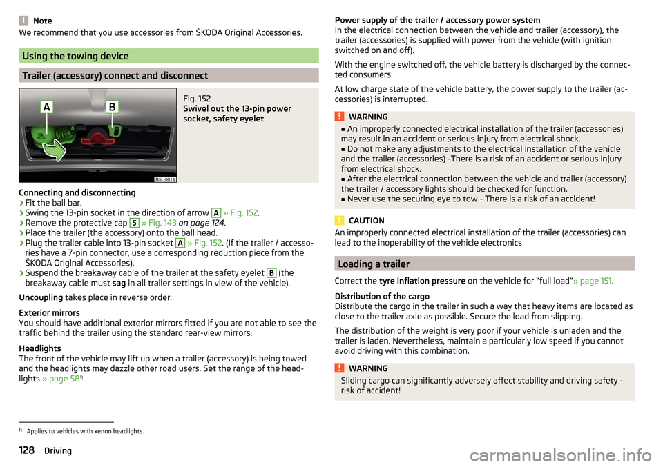
Fig. 152
Swivel out the 13-pin power
socket, safety eyelet
Connecting and disconnecting
âº
Fit the ball bar.
âº
Swing the 13-pin socket in the direction of arrow
A
» Fig. 152 .
âº
Remove the protective cap
5
» Fig. 143 on page 124 .
âº
Place the trailer (the accessory) onto the ball head.
âº
Plug the trailer cable into 13-pin socket
A
» Fig. 152 . (If the trailer / accesso-
ries have a 7-pin connector, use a corresponding reduction piece from the
Å KODA Original Accessories).
âº
Suspend the breakaway cable of the trailer at the safety eyelet
B
(the
breakaway cable must sag in all trailer settings in view of the vehicle).
Uncoupling takes place in reverse order.
Exterior mirrors
You should have additional exterior mirrors fitted if you are not able to see the
traffic behind the trailer using the standard rear-view mirrors.
Headlights
The front of the vehicle may lift up when a trailer (accessory) is being towed
and the headlights may dazzle other road users. Set the range of the head-
lights » page 58 1)
.
Power supply of the trailer / accessory power system
In the electrical connection between the vehicle and trailer (accessory), the
trailer (accessories) is supplied with power from the vehicle (with ignition
switched on and off).
With the engine switched off, the vehicle battery is discharged by the connec-
ted consumers.
At low charge state of the vehicle battery, the power supply to the trailer (ac-
cessories) is interrupted.WARNINGâ An improperly connected electrical installation of the trailer (accessories)
may result in an accident or serious injury from electrical shock.â
Do not make any adjustments to the electrical installation of the vehicle
and the trailer (accessories) -There is a risk of an accident or serious injury
from electrical shock.
â
After the electrical connection between the vehicle and trailer (accessory)
the trailer / accessory lights should be checked for function.
â
Never use the securing eye to tow - There is a risk of an accident!
CAUTION
An improperly connected electrical installation of the trailer (accessories) can
lead to the inoperability of the vehicle electronics.
Loading a trailer
Correct the tyre inflation pressure on the vehicle for âfull loadâ » page 151.
Distribution of the cargo
Distribute the cargo in the trailer in such a way that heavy items are located as
close to the trailer axle as possible. Secure the load from slipping.
The distribution of the weight is very poor if your vehicle is unladen and the
trailer is laden. Nevertheless, maintain a particularly low speed if you cannot
avoid driving with this combination.
WARNINGSliding cargo can significantly adversely affect stability and driving safety -
risk of accident!1)
Applies to vehicles with xenon headlights.
128Driving
Page 132 of 200
Brakes
Apply the brakes in good time! If the trailer is fitted with a trailer brake, apply
the brakes gently at first, then brake firmly. This will avoid brake jolts resulting
from the trailer wheels locking.
On downhill sections shift down a gear in good time to also use the engine as
a brake.WARNINGAlways drive particularly carefully with the trailer.
CAUTION
With frequent towing, the vehicle is excessively loaded so this must also be
checked between service intervals.
Anti-theft alarm system
The alarm is triggered if, with a vehicle with activated anti-theft alarm (here-
after only warning system), the electrical connection to the trailer (accessory)
is interrupted.
Always switch off the anti-theft alarm system before a trailer (accessory) is
coupled or uncoupled » page 51.
Conditions for including a trailer (accessory) in the anti-theft alarm system. The vehicle is factory-fitted with an anti-theft alarm system and a towing
device.
The trailer (accessory) is electrically connected to the towing vehicle by
means of the trailer socket.
The electrical system of the vehicle and trailer (accessory) is functional.
The vehicle is locked and the anti-theft alarm system is activated.
The trailer (accessory) is not equipped with LED taillights.
ï¥ï¥ï¥ï¥ï¥130Driving
Page 135 of 200

WARNINGâ No changes may be made to airbag system components, the front bump-
er and the bodywork.â
Any work on the airbag system including the installation and removal of
system components due to other repair work (e.g. removal of the steering
wheel) must only be carried out by a specialist garage.
â
Do not manipulate individual parts of the airbag system, as this might re-
sult in the airbag being deployed.
â
If the airbag has been deployed, the airbag system must be replaced.
WARNINGThe airbag system operates using pressure sensors located in the front
doors. For this reason, no adjustments may be carried out to the doors or
door panels (e.g. installation of additional loudspeakers). Resulting damage
can impair the functioning of the airbag system - There is a risk of acci-
dents and fatal injuries! The following guidelines must be observed.â
Any work on the front doors and their door panels must be carried out by
a specialist garage.
â
Never drive the vehicle with the inner door panels removed or with open-
ings in the panelling.
Acceptance and recycling of used vehicles
Read and observe
on page 131 first.
All new Å KODA vehicles are 95% recyclable.
Service intervals
ï¤ Introduction
This chapter contains information on the following subjects:
Overview of service intervals
134
Fixed service intervals QI1 - QI4
134
Variable service interval QI6
134
Digital Service Plan
135
The service interval display in the display of the instrument cluster will remind
you to carry out every service stipulated by the manufacturer at the right time
in order to prevent you from forgetting any » page 44.
ï¤The completion of services can be verified through the printed verification
from the digital service schedule and the respective receipts.
The specified service intervals are tailored to normal operating conditions.
In the case of aggravated operating conditions, it will be necessary to have
some service work carried out before the date of the next regular service or
between the specified service intervals. This applies mainly to the cleaning or
the replacement of the air filter insert in regions with heavy dust pollution as
well as checking and replacing the toothed belt, but also to vehicles with die-
sel particle filters, which can put greater strain on the engine oil.
The following is taken to mean aggravated operating conditions: ⶠFuel containing sulphur.
ⶠFrequent short trips.
ⶠLonger periods of engine idling (e.g. taxis).
ⶠOperation in areas with heavy dust pollution.
ⶠFrequent trailer operation.
ⶠPredominantly stop-and-go traffic as is e.g. often the case in city driving.
ⶠOperation predominantly during winter.
You will be told at the specialist garage whether the operating conditions of
your vehicle may make it necessary for service work to be carried out between
the normal service intervals.
Different service charges may apply according to the particular scope of work
required, the vehicle type and specification, and your vehicleâs condition.
Note
â The customer is responsible for covering the cost of all services including
changing or replenishing the oil, even during the warranty period, unless sta-
ted otherwise in the Å KODA AUTO warranty terms or other agreements.â
You will be informed about the service checks and actions at each service by
the specialist garage.
133Care and maintenance
Page 143 of 200
Operating under different weather conditions
Use only diesel in accordance with the current or expected weather conditions.
Ask the petrol station personnel whether the diesel fuel offered corresponds
to these conditions.
CAUTION
The following instructions must be observed, otherwise there is a risk of dam-
age to the engine and to the exhaust system.â
If a different fuel other than diesel fuel, which complies to the above men-
tioned standards (e.g. petrol) is put into the tank, do not start the engine or
switch on the ignition!
â
The biofuel RME must not be used!
CAUTION
Diesel fuel additivesâ The diesel fuel in accordance with the prescribed standards meets all the
conditions for a smooth running engine. Therefore, we recommend that you do
not add any fuel additives to the diesel - there is a risk of engine damage or
damage to the exhaust system.
AdBlue ®
And its refilling
ï¤ Introduction
This chapter contains information on the following subjects:
Check level
141
AdBlue ®
refill
142
In order to reduce pollutant emissions from vehicles with diesel engines and
the SCR catalyst, a urea - AdBlue ®
solution is injected into the exhaust system.
Only use AdBlue ®
that corresponds to the standard ISO 22241-1. Do not add
additives to AdBlue ®
.
The AdBlue ®
consumption is approx. 1.2 l - 1.6 l/1000 km, depending on driving
style, the operating temperature of the system and on the weather conditions.
AdBlue ®
-tank filling level is about 8.5 litres.
WARNINGAdBlue®
can cause skin, eye and respiratory irritation. If your eyes or skin
come into contact with the AdBlue ®
fluid, immediately wash the affected
area for a few minutes with a lot of water. If necessary get medical assis-
tance.
CAUTION
AdBlue ®
attacks the surface of some materials (e.g. as painted parts, plastics,
fabrics). Clean the areas affected with AdBlue ®
using a damp cloth and plenty
of cold water. Remove any dried AdBlue ®
with warm water and a sponge.
Note
â The AdBlue ®
solution freezes at a temperature of -11 °C and below. The sys-
tem has a heater to ensure the operability at low temperatures.â
We recommend purchasing AdBlue ®
refill bottles from the Å KODA original
parts.
â
The working life of the AdBlue ®
solution is 4 years. After this time, the solu-
tion must be replaced by a specialist garage.
â
AdBlue ®
is a registered trademark of the VDA. AdBlue ®
is also known as AUS
32 (Aqueous Urea Solution) or DEF (Diesel Exhaust Fluid).
Check level
Read and observe
and on page 141 first.
The filler neck of AdBlue ®
Tank is located in the luggage compartment under
the symbol ï¾ and the cap marked with the lettering âAdBlue ®
â » Fig. 156 on
page 142 .
The AdBlue ®
level is automatically monitored.
If the available travel distance that can be completed with the remaining AdBl- ue ®
tank capacity drops to about 2400 km, the warning ï¾ appears on the in-
strument cluster and a request for replenishment of AdBlue ®
appears.
An indication also appears in the instrument cluster showing the maximum
and minimum AdBlue ®
tank capacity.
If the available travel distance that can be driven with the existing AdBlue ®
tank capacity drops down to 0 km, then no motor start is possible.
The distance which can still be driven with the remaining AdBlue ®
, can be de-
termined using the travel data » page 30.
ï¤141Inspecting and replenishing
Page 146 of 200
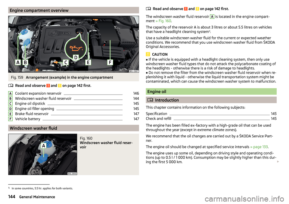
Engine compartment overviewFig. 159
Arrangement (example) in the engine compartment
Read and observe
and on page 142 first.
Coolant expansion reservoir
146
Windscreen washer fluid reservoir
144
Engine oil dipstick
145
Engine oil filler opening
145
Brake fluid reservoir
147
Vehicle battery
147
Windscreen washer fluid
Fig. 160
Windscreen washer fluid reser-
voir
ï¤ABCDEFRead and observe and on page 142 first.
The windscreen washer fluid reservoir
A
is located in the engine compart-
ment » Fig. 160 .
The capacity of the reservoir A is about 3 litres or about 5.5 litres on vehicles
that have a headlight cleaning system 1)
.
Use a suitable windscreen washer fluid for the current or expected weather
conditions. We recommend that you use windscreen washer fluid from Å KODA
Original Accessories.
CAUTION
â If the vehicle is equipped with a headlight cleaning system, then only use
windscreen washer fluid types that do not attack the polycarbonate coating of
the headlights - otherwise there is a risk of damage to headlights.â
Do not remove the filter from the windscreen washer fluid reservoir when re-
plenishing it with liquid - otherwise the liquid transportation system might be
contaminated, which can cause the windscreen washer system to malfunction.
Engine oil
ï¤ Introduction
This chapter contains information on the following subjects:
Specification
145
Check and refill
145
The engine has been filled ex-factory with a high-grade oil that can be used
throughout the year (except in extreme climate zones).
We recommend that the oil changes are carried out by a Å KODA Service Part- ner.
The engine oil should be changed at specified service intervals » page 133.
The engine uses up some oil, depending on driving style and operating condi-
tions (up to 0.5 l / 1 000 km). Consumption may be slightly higher than this dur-
ing the first 5 000 km. ï£
ï¤
1)
In some countries, 5.5 ltr. applies for both variants.
144General Maintenance
Page 147 of 200
WARNINGThe following instructions must be followed at all times when working on
the engine compartment » page 142.
CAUTION
Do not add any additives to the engine oil - There is a risk of engine damage.
Note
We recommend that you use oils from Å KODA Original Accessories.
Specification
Read and observe
and on page 145 first.
The specifications (VW standards) stated in the following can be indicated sep-arately or together with other specifications on the bottle.
Vehicles with variable service intervals
Petrol enginesSpecification1.2 l/81 kW TSI
VW 504 00
1.4 l/92, 110 kW TSI1.8 ltr./112 kW TSIDiesel enginesSpecification2.0 l/81, 103, 110 kW TDI CRVW 507 00
Vehicles with fixed service intervals
Petrol enginesSpecification1.2 l/81 kW TSI
VW 502 00
1.4 l/92, 110 kW TSI1.6 l./81 kW MPI
1.8 ltr./112 kW TSI
VW 502 00applies to Russia
SAE 0W-30 VW 502 00 / 505 00Diesel enginesSpecification2.0 l/81, 103, 110 kW TDI CRVW 507 00
Engine oil VW 505 01 can optionally be used in diesel engines without a DPF.
ï¤CAUTIONâ
If no prescribed engine oil is available, then max. 0.5 l oil of the following
specifications can be refilled. â Petrol engines: ACEA A3/ACEA B4 or API SN, (API SM);
â Diesel engines: ACEA C3 or API CJ-4.
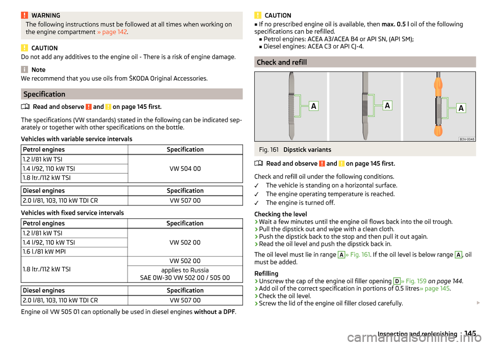
Check and refill
Fig. 161
Dipstick variants
Read and observe
and on page 145 first.
Check and refill oil under the following conditions. The vehicle is standing on a horizontal surface.
The engine operating temperature is reached.
The engine is turned off.
Checking the level
âº
Wait a few minutes until the engine oil flows back into the oil trough.
âº
Pull the dipstick out and wipe with a clean cloth.
âº
Push the dipstick back to the stop and then pull it out again.
âº
Read the oil level and push the dipstick back in.
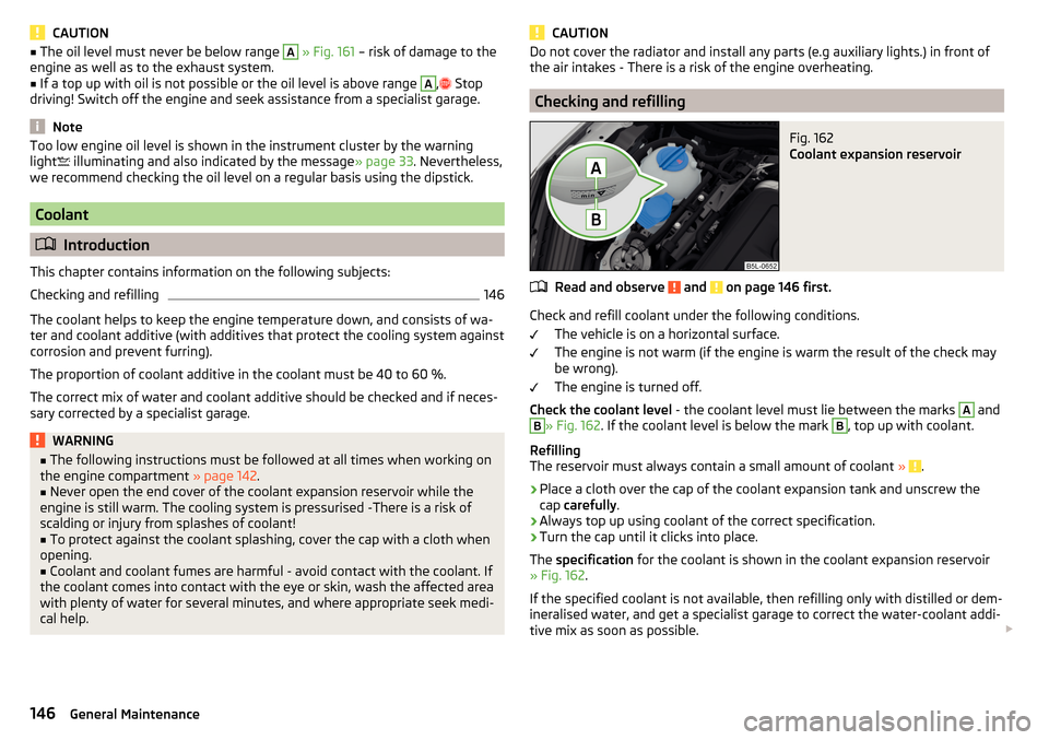
The oil level must lie in range
A
» Fig. 161 . If the oil level is below range
A
, oil
must be added.
Refilling
âº
Unscrew the cap of the engine oil filler opening
D
» Fig. 159 on page 144 .
âº
Add oil of the correct specification in portions of 0.5 litres » page 145.
âº
Check the oil level.
âº
Screw the lid of the engine oil filler closed carefully. ï£
ï¤ï¥ï¥ï¥145Inspecting and replenishing
Page 148 of 200
CAUTIONâ The oil level must never be below range A » Fig. 161 â risk of damage to the
engine as well as to the exhaust system.â
If a top up with oil is not possible or the oil level is above range
A
, ï²
Stop
driving! Switch off the engine and seek assistance from a specialist garage.
Note
Too low engine oil level is shown in the instrument cluster by the warning
light ï§ illuminating and also indicated by the message » page 33. Nevertheless,
we recommend checking the oil level on a regular basis using the dipstick.
Coolant
ï¤ Introduction
This chapter contains information on the following subjects:
Checking and refilling
146
The coolant helps to keep the engine temperature down, and consists of wa- ter and coolant additive (with additives that protect the cooling system against
corrosion and prevent furring).
The proportion of coolant additive in the coolant must be 40 to 60 %.
The correct mix of water and coolant additive should be checked and if neces-
sary corrected by a specialist garage.
WARNINGâ The following instructions must be followed at all times when working on
the engine compartment » page 142.â
Never open the end cover of the coolant expansion reservoir while the
engine is still warm. The cooling system is pressurised -There is a risk of
scalding or injury from splashes of coolant!
â
To protect against the coolant splashing, cover the cap with a cloth when
opening.
â
Coolant and coolant fumes are harmful - avoid contact with the coolant. If
the coolant comes into contact with the eye or skin, wash the affected area
with plenty of water for several minutes, and where appropriate seek medi-
cal help.
CAUTIONDo not cover the radiator and install any parts (e.g auxiliary lights.) in front of
the air intakes - There is a risk of the engine overheating.
Checking and refilling
Fig. 162
Coolant expansion reservoir
Read and observe and on page 146 first.
Check and refill coolant under the following conditions.
The vehicle is on a horizontal surface.
The engine is not warm (if the engine is warm the result of the check may
be wrong).
The engine is turned off.
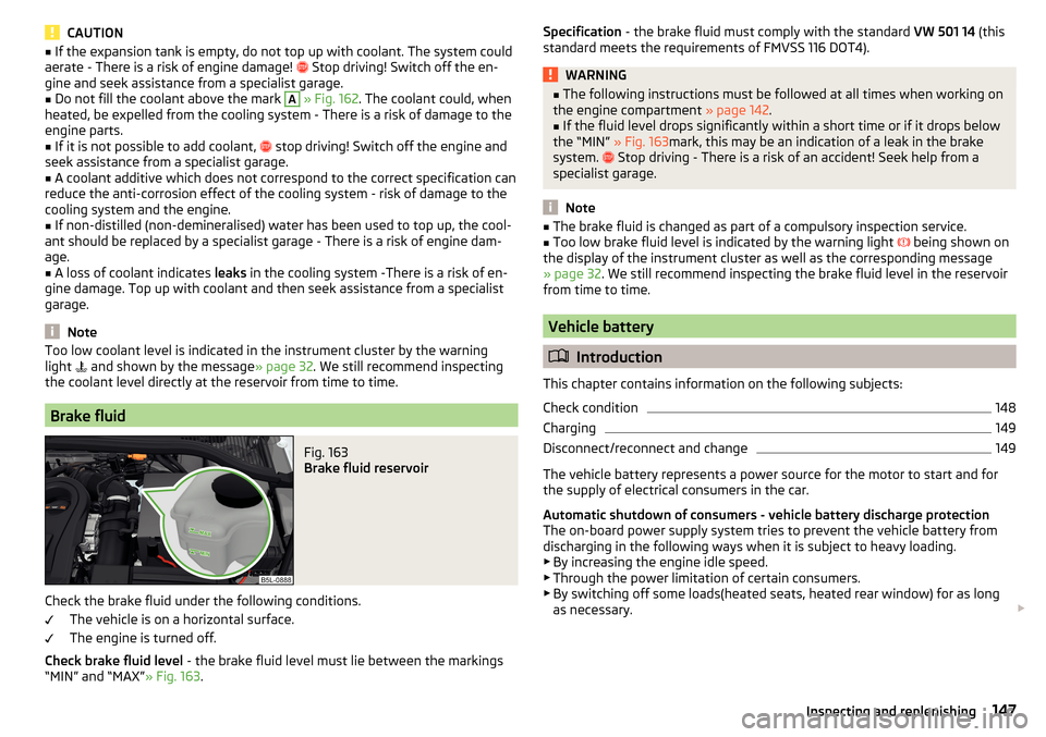
Check the coolant level - the coolant level must lie between the marks
A
and
B
» Fig. 162. If the coolant level is below the mark
B
, top up with coolant.
Refilling
The reservoir must always contain a small amount of coolant »
.
âº
Place a cloth over the cap of the coolant expansion tank and unscrew the
cap carefully .
âº
Always top up using coolant of the correct specification.
âº
Turn the cap until it clicks into place.
The specification for the coolant is shown in the coolant expansion reservoir
» Fig. 162 .
If the specified coolant is not available, then refilling only with distilled or dem-
ineralised water, and get a specialist garage to correct the water-coolant addi-
tive mix as soon as possible. ï£
ï¤ï¥ï¥ï¥146General Maintenance
Page 149 of 200
CAUTIONâ If the expansion tank is empty, do not top up with coolant. The system could
aerate - There is a risk of engine damage! ï² Stop driving! Switch off the en-
gine and seek assistance from a specialist garage.â
Do not fill the coolant above the mark
A
» Fig. 162 . The coolant could, when
heated, be expelled from the cooling system - There is a risk of damage to the
engine parts.
â
If it is not possible to add coolant, ï²
stop driving! Switch off the engine and
seek assistance from a specialist garage.
â
A coolant additive which does not correspond to the correct specification can
reduce the anti-corrosion effect of the cooling system - risk of damage to the
cooling system and the engine.
â
If non-distilled (non-demineralised) water has been used to top up, the cool-
ant should be replaced by a specialist garage - There is a risk of engine dam-
age.
â
A loss of coolant indicates leaks in the cooling system -There is a risk of en-
gine damage. Top up with coolant and then seek assistance from a specialist
garage.
Note
Too low coolant level is indicated in the instrument cluster by the warning
light ï¯ and shown by the message » page 32. We still recommend inspecting
the coolant level directly at the reservoir from time to time.
Brake fluid
Fig. 163
Brake fluid reservoir
Check the brake fluid under the following conditions.
The vehicle is on a horizontal surface.
The engine is turned off.
Check brake fluid level - the brake fluid level must lie between the markings
âMINâ and âMAXâ » Fig. 163.
ï¥ï¥Specification - the brake fluid must comply with the standard VW 501 14 (this
standard meets the requirements of FMVSS 116 DOT4).WARNINGâ The following instructions must be followed at all times when working on
the engine compartment » page 142.â
If the fluid level drops significantly within a short time or if it drops below
the âMINâ » Fig. 163mark, this may be an indication of a leak in the brake
system. ï²
Stop driving - There is a risk of an accident! Seek help from a
specialist garage.
Note
â The brake fluid is changed as part of a compulsory inspection service.â Too low brake fluid level is indicated by the warning light ï¨ being shown on
the display of the instrument cluster as well as the corresponding message
» page 32 . We still recommend inspecting the brake fluid level in the reservoir
from time to time.
Vehicle battery
ï¤ Introduction
This chapter contains information on the following subjects:
Check condition
148
Charging
149
Disconnect/reconnect and change
149
The vehicle battery represents a power source for the motor to start and for the supply of electrical consumers in the car.
Automatic shutdown of consumers - vehicle battery discharge protection
The on-board power supply system tries to prevent the vehicle battery from
discharging in the following ways when it is subject to heavy loading. ⶠBy increasing the engine idle speed.
ⶠThrough the power limitation of certain consumers.
ⶠBy switching off some loads(heated seats, heated rear window) for as long
as necessary. ï£
147Inspecting and replenishing
Page 151 of 200

Battery discharge
If frequent short journeys are made, the vehicle battery does not recharge suf-
ficiently.
The battery capacity decreases at low temperatures.
If the vehicle is not used for longer than 3 to 4 weeks, disconnect the negative
terminal ï
of the battery or charge the battery completely with a very low
charging current.
Charging
Read and observe
and on page 148 first.
Only charge the battery when the ignition and all consumers are switched off.
Refer to the instructions of the charger manufacturer.
Charging
âº
For vehicles withthe START-STOPsystem or aux. heating, connect the
ï ter-
minal of the charger on the batteryâs ï pole, the
ï terminal of the charger to
the earth point of the engine » page 161.
âº
For vehicles without the START-STOPsystem or aux. heating, connect the
charger terminals to the corresponding battery poles ( ï to
ï,
ï to
ï).
âº
Plug the mains cable of the charger into the power socket and switch on the
device.
âº
After charging has been successful: Switch off the charger and remove the
mains cable from the power socket.
âº
Disconnect the terminals of the charger from the vehicle battery.
A charging current of 0.1 multiple of the total vehicle battery capacity (or low-
er) must be used until full charging is achieved.
WARNINGâ When charging the vehicle battery, hydrogen is released - risk of explo-
sion. An explosion can be caused through sparking while unclamping or
loosening the cable plug.â
So-calledâquick-chargingâ of the vehicle battery is dangerous and re-
quires a special charger and specialist knowledge. Therefore, haveâQuick
loadingâ carried out by a specialist garage.
ï¤Disconnect/reconnect and change
Read and observe
and on page 148 first.
The new vehicle battery must have the same capacity, voltage, current and the
same size as the original Battery.
We recommend you have the battery replaced by a specialist garage.
âº
To disconnect , switch off the ignition and disconnect the negative terminal
first ï
, then disconnect the positive terminal ï
.
âº
When reconnecting the battery, reconnect the positive terminal ï
first, then
connect the negative terminal ï
.
After disconnecting and re-connecting the vehicle battery, the following func- tions or devices are partially or completely inoperative.
Function / deviceOperating measureWindows» page 55Panorama sliding/tilting roof» page 57Sun screen» page 57Time settings» page 39
CAUTION
â Disconnect the battery only with the ignition and consumers turned off -
There is a risk of damaging the electrical system of the vehicle.â
Before disconnecting the battery, always close the electric windows and the
tilt/slide sunroof - otherwise the fitting units for these may malfunction.
â
Under no circumstances mix up the charging cables â There is a risk of fire.
Note
After disconnecting and reconnecting the vehicle battery, we recommend hav-
ing the vehicle checked by a specialist to ensure that the full functionality of
the vehicle is guaranteed.ï¤149Inspecting and replenishing