check engine SKODA YETI 2016 1.G / 5L Owner's Guide
[x] Cancel search | Manufacturer: SKODA, Model Year: 2016, Model line: YETI, Model: SKODA YETI 2016 1.G / 5LPages: 200, PDF Size: 28.98 MB
Page 162 of 200
Preparing to use the breakdown kitRead and observe
on page 159 first.
For safety's sake, the following instructions must be observed before
undertaking a wheel repair on a road.
ŌĆ║
Park the vehicle as far as possible away from the traffic flow - choose a place
with a flat and firm surface.
ŌĆ║
Switch off the engine.
ŌĆ║
For vehicles with manual transmission , select 1. gear.
ŌĆ║
For vehicles with automatic transmission , place the selector lever in the P
position.
ŌĆ║
Firmly apply the handbrake.
ŌĆ║
Switch on the hazard warning lights and set up the warning triangle at the
prescribed distance.
ŌĆ║
Have all the occupants get out . While the repair is being carried out, the pas-
sengers should not stand on the road (instead they should remain behind a
crash barrier, for instance).
ŌĆ║
Uncouple any trailers.
Sealing and inflating tyres
Read and observe
on page 159 first.
Sealing
ŌĆ║
Unscrew the valve cap from the damaged tyre.
ŌĆ║
Insert the valve remover
2
┬╗ Fig. 177 on page 159 on the valve insert, so that
the valve insert fits into the slot of the valve remover.
ŌĆ║
Unscrew the valve insert and place it on a clean base (rag, paper etc.).
ŌĆ║
Forcefully shake bottle
10
┬╗ Fig. 177 on page 159 several times.
ŌĆ║
Firmly screw the inflation hose
3
onto the tyre inflater bottle
10
. The film on
the bottle cap is pierced.
ŌĆ║
Remove the plug from the inflation hose
3
and insert the bottle onto the
tyre valve.
ŌĆ║
Hold the bottle
10
with the bottom facing upwards and fill all of the sealing
agent from the tyre inflator bottle into the tyre.
ŌĆ║
Remove the filler plug from the tyre valve.
ŌĆ║
Screw in the valve insert with the valve remover
2
.
Inflating
ŌĆ║
Screw the tyre inflation hose
8
┬╗ Fig. 177 on page 159 firmly onto the tyre
valve.
’āż’āżŌĆ║ For vehicles with
manual transmission , set the lever in the neutral position.ŌĆ║On vehicles with automatic transmission , place the selector lever in the P
position.ŌĆ║
Check that the screw for the tire pressure reduction
6
is closed.
ŌĆ║
Start the engine.
ŌĆ║
Plug the connector
4
into 12 volt socket ┬╗ page 79.
ŌĆ║
Switch on the air compressor with the ON and OFF switch
9
.
ŌĆ║
Once tyre inflation pressure of 2.0-2.5 bar has been reached, turn off the air
compressor. Maximum run time of 6 minutes ┬╗ .
ŌĆ║
If you cannot reach an air pressure of 2.0 - 2.5 bar, unscrew the tyre inflation
hose
8
from the tyre valve.
ŌĆ║
Drive the vehicle 10 metres forwards or backwards to allow the sealing agent
to ŌĆ£distributeŌĆØ in the tyre.
ŌĆ║
Firmly screw the tyre inflation hose
8
back onto the tyre valve and repeat
the inflation process.
ŌĆ║
Stick the sticker
1
┬╗ Fig. 177 on page 159 on the dashboard in the driver's
field of view.
At a tyre inflation pressure of 2.0ŌĆō2.5 bar, the journey can be continued at a
maximum speed of 80 km/h or 50 mph.
WARNINGŌ¢Ā If the tire does not inflate at least. 2.0 bar, the damage is too great. The
sealing agent cannot be used to seal the tyre. ’é▓ Stop driving! Seek help
from a specialist garage.Ō¢Ā
The tyre inflation hose and air compressor may get hot as the tyre is be-
ing inflated ŌĆō risk of burning.
CAUTION
Switch off the air compressor if it has been running for as much as 6 minutes ŌĆō
There is a risk of damage to the compressor! Allow the air compressor to cool a
few minutes before switching it on again.
Information on driving with repaired tyres
Read and observe
on page 159 first.
The inflation pressure of the repaired tyre must be checked after driving for 10
minutes.
If the tyre inflation pressure is 1.3 bar or less
ŌĆ║
The tyre cannot be properly sealed with the breakdown kit. ’é▓
Stop driving!
Seek help from a specialist garage. ’éŻ
’āż160Do-it-yourself
Page 169 of 200

Attaching the windscreen wiper bladeŌĆ║Slide the windscreen wiper blade in the opposite direction to arrow 3 until it
locks into place. Check that the windscreen wiper blade is correctly attached.ŌĆ║
Fold the windscreen wiper arm back to the windscreen.
ŌĆ║
Turn on the ignition and press the lever in the direction of the arrow
┬╗ Fig. 189 .
The windscreen wiper arms move into the home position.
Replacing the rear window wiper blade
Fig. 191
Changing the rear window wiper blade
Read and observe
on page 166 first.
Removing the wiper blade
ŌĆ║
Lift the wiper arm ┬╗ page 167 from the window in the direction of arrow
1
┬╗ Fig. 191.
ŌĆ║
Tilt the wiper blade to the stop in the same direction.
ŌĆ║
Grip the wiper arm and press securing latch
A
down in the direction of arrow
2
.
ŌĆ║
Remove the wiper blade in the direction of the arrow
3
.
Attaching the windscreen wiper blade
ŌĆ║
Slide the windscreen wiper blade in the opposite direction to arrow
3
until it
locks into place. Check that the windscreen wiper blade is correctly attached.
ŌĆ║
Fold the windscreen wiper arm back to the windscreen.
’āżFuses and light bulbs
Fuses
’āż Introduction
Fig. 192
Blown fuse
This chapter contains information on the following subjects:
Fuses in the dashboard
168
Fuse arrangement in the dashboard
168
Fuses in the engine compartment
169
Fuse arrangement in the engine compartment
169
Individual electrical circuits are protected by fuses. A blown fuse is recognisa-
ble from the melted-through metal strip ┬╗ Fig. 192.
WARNINGAlways read and observe the warnings before completing any work in the
engine compartment ┬╗ page 142.
CAUTION
Ō¢Ā
Replace the faulty fuse with a new one of the same amperage.Ō¢ĀIf a newly inserted fuse again blows after a short time, then seek assistance
from a specialist garage.Ō¢Ā
ŌĆ£Do not repairŌĆØ the fuses and do not replace them with stronger fuses -
There is a risk of fire and damage to another electrical system.
Note
Ō¢Ā We recommend always carrying replacement fuses in the vehicle.Ō¢ĀThere can be several power consuming devices for one fuse. Multiple fuses
may exist for a single power consuming device.167Fuses and light bulbs
Page 172 of 200
No.Consumer18Music amplifier19Windscreen wipers20Control valve for fuel pressure, high pressure pump21Lambda probe22Clutch pedal switch, brake pedal switch23Coolant pump, loading pressure control valve, switchover valve for
radiator, fuel pump24Active charcoal filter, exhaust gas recirculation valve, radiator fan25ABS26Left front headlight, left taillight27Glow plug system28Windscreen heater29Power to the internal fuse carrier (fuses no. 24,27,31,32), electrically
adjustable seats30Terminal X a)a)
In order not to drain the battery unnecessarily when starting the engine, the electrical components of
this terminal are automatically switched off.
Bulbs
’āż Introduction
This chapter contains information on the following subjects:
Bulb arrangement in the front headlights
171
Changing bulbs for low and main beam (Halogen headlights)
171
Remove protective guard for foglights
171
Protective grille for removing fog lights- plug for Park Assist sensor
172
Changing light bulbs for fog lights
172
Changing the bulb for the licence plate light
173
Removing/installing taillights
173
Replacing the bulbs in the taillight assembly
174
We recommend having bulbs replaced by a specialist garage or seeking other
expert help in the event of any uncertainties.
Ō¢Č Switch off the ignition and all of the lights before replacing a bulb.
Ō¢Č Faulty bulbs must only be replaced with the same type of bulbs. The designa-
tion is located on the light socket or the glass bulb.
We recommend having the headlight settings checked by a specialist garage after replacing a bulb in the low, high or fog beam.
In the case of failure of a Xenon gas discharge bulb or an LED diode, visit a
specialist garage.WARNINGŌ¢Ā Always read and observe the warnings before completing any work in the
engine compartment ┬╗ page 142.Ō¢Ā
Accidents can be caused if the road in front of the vehicle is not suffi-
ciently illuminated and the vehicle cannot or can only be seen with difficul-
ty by other road users.
Ō¢Ā
Bulbs H7 and H4 are pressurised and may burst when changed - there is a
risk of injury. We therefore recommended wearing gloves and safety
glasses when changing a bulb.
Ō¢Ā
Do not carry out any work on the Xenon gas discharge lamps - risk of
death!
CAUTION
Do not take hold of the glass bulb with naked fingers (even the smallest
amount of dirt reduces the working life of the light bulb). Use a clean cloth,
napkin, or similar.
Note
Ō¢Ā This Owner's Manual only describes the replacement of bulbs where it is pos-
sible to replace the bulbs on your own without any complications arising. Other
bulbs must be replaced by a specialist garage.Ō¢Ā
We recommend that a box of replacement bulbs always be carried in the ve-
hicle.
170Do-it-yourself
Page 187 of 200
C
Camera See reversing camera
116
Car battery Check condition
148
Cover148
Disconnecting and reconnecting149
Replacing149
Winter operation148
Car care Exterior
136
Interior138
Car computer See multifunction display
41
Care and maintenance131
Carrier93
Car washing135
Exterior136
Interior138
Washing135
Central locking47
Problems51
Central locking button49
Changing Batteries for the removable light
164
Battery164
Windscreen wiper blades167
Changing a wheel155
Changing155
Changing gear Selector lever
106
Changing wheels Wheels
155
Charging a vehicle battery149
Check Brake fluid
147
Engine oil145
Fasten ball rod properly126
Oil level145
Checking Battery status148
Coolant146
Checks Statutory checks
131
Children and safety21
Child safety lock51
Child seat21
Classification23
Installation location23, 24
ISOFIX24
on the front passenger seat22, 23
TOP TETHER25
Cigarette lighter78
Climatronic air distribution control
96
Automatic operation95
Operating elements94
Clothes hook82
Cockpit27
Lighting62
Comfort control window
55
Comfort signalling59
COMING HOME61
Compartments75
Component protection132
Computer See multifunction display
41
Convenience operation sliding / tilting roof
57
Coolant146
Checking146
Refilling146
Temperature display29
Warning light32
CORNER See Fog lights with the CORNER function
61
Cornering lightsDisplay messages34
Correct routing of seat belt
14
Correct seated position10
Correct seating position12
Cruise control system Warning light
37
Cruise Control System121
Cup holders77
D
DAY LIGHT see Daylight running lights
59
Daylight running lights59
Deactivation Airbag
19
Delayed locking of the boot lid See boot lid
53
Departure angle179
Diesel140
Diesel fuel140
Diesel particle filter (DPF)35
Digital Clock39
Digital Service Plan135
Dipped beam58
Dipstick145
Display Cardinal points
38
Coolant temperature29
Fuel level29
Gear changes39
In the instrument cluster38
Service intervals44
Display MAXI DOT42
Display of the second speed39
Display of the second speedometer39
Disposal Acceptance and recycling of used vehicles
133
185Index
Page 188 of 200
DoorChild safety lock51
Emergency locking165
Emergency locking of the driver's door165
Opening/Closing50
warning light door open32
Door alarm38
Door open warning light
32
Drive Driving through water
109
Driver Steering Recommendation (DSR)111
Driving Emissions
177
Fuel consumption177
through water109
Top speed181
DSR111
E
Economical driving
108
EDL111
Electrical power windows55
Button in the rear doors54
Electric power windows53
Electric window Buttons in the driver┬┤s door
54
Electric windows Operational faults
55
Electronic Differential Lock (EDL)111
Electronic immobiliser100
Emergency Hazard warning light system
61
Jump-starting161
Selector lever-unlocking166
Starting / stopping the engine with the push of a button
101
Starting the engine / stopping with the push of a button
102
Towing the vehicle162
Towing the vehicle using the trailer device163
Tyre repair159
Unlocking/locking the door165
Unlocking / locking the door165
Emergency equipment Fire extinguisher
154
First aid kit154
Jack155
Reflective vest154
Vehicle tool kit155
Warning triangle154
Emission control system35
Emissions177
Engine Running in
108
Engine compartment142
Brake fluid147
Coolant146
Engine oil144
Overview144
Vehicle battery147
Windscreen washer fluid144
Engine drag torque control (MSR)110
Engine number175
engine oil specification
145
Engine oil144
Check145
Oil changing144
Refilling145
Warning light33
EPC35
ESC Operation
110
Warning light34
Extended warranty5
Exterior temperature41
F
Fastening elements
87
Fatigue detection122
Films136
Fire extinguisher154
First aid kit154
Flashing59
Flexible storage compartment88
Floor covering in the luggage compartment88
Fog lights Warning light
37
Fog lights/rear fog light60
Fog lights with the CORNER function61
folding table on the rear seat backrest
84
Folding table on the front seat backrest
83
Footmats106
see footmats106
Force limiter Sliding/tilting roof
56
Window55
Front seats68
Fuel139
Diesel140
Fuel gauge29
refer to Fuel139
Refuelling139
Unleaded petrol140
Warning light36
Fuel consumption177
Fuel filter information messages
30
Fuel reserve36
Fuses167
in the dashboard168
in the engine compartment169
186Index
Page 189 of 200
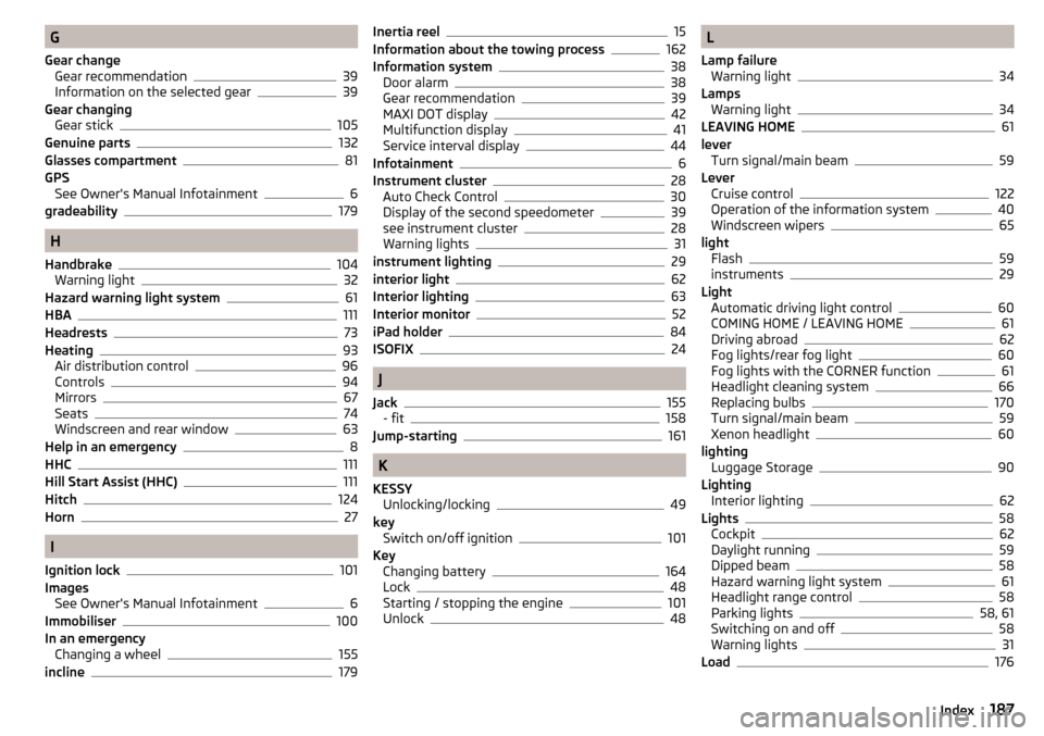
G
Gear change Gear recommendation
39
Information on the selected gear39
Gear changing Gear stick
105
Genuine parts132
Glasses compartment81
GPS See Owner's Manual Infotainment
6
gradeability179
H
Handbrake
104
Warning light32
Hazard warning light system61
HBA111
Headrests73
Heating93
Air distribution control96
Controls94
Mirrors67
Seats74
Windscreen and rear window63
Help in an emergency8
HHC111
Hill Start Assist (HHC)111
Hitch124
Horn27
I
Ignition lock
101
Images See Owner's Manual Infotainment
6
Immobiliser100
In an emergency Changing a wheel
155
incline179
Inertia reel15
Information about the towing process162
Information system38
Door alarm38
Gear recommendation39
MAXI DOT display42
Multifunction display41
Service interval display44
Infotainment6
Instrument cluster28
Auto Check Control30
Display of the second speedometer39
see instrument cluster28
Warning lights31
instrument lighting29
interior light62
Interior lighting63
Interior monitor52
iPad holder84
ISOFIX24
J
Jack
155
- fit158
Jump-starting161
K
KESSY Unlocking/locking
49
key Switch on/off ignition
101
Key Changing battery
164
Lock48
Starting / stopping the engine101
Unlock48
L
Lamp failure Warning light
34
Lamps Warning light
34
LEAVING HOME61
lever Turn signal/main beam
59
Lever Cruise control
122
Operation of the information system40
Windscreen wipers65
light Flash
59
instruments29
Light Automatic driving light control
60
COMING HOME / LEAVING HOME61
Driving abroad62
Fog lights/rear fog light60
Fog lights with the CORNER function61
Headlight cleaning system66
Replacing bulbs170
Turn signal/main beam59
Xenon headlight60
lighting Luggage Storage
90
Lighting Interior lighting
62
Lights58
Cockpit62
Daylight running59
Dipped beam58
Hazard warning light system61
Headlight range control58
Parking lights58, 61
Switching on and off58
Warning lights31
Load176
187Index