transmission oil SKODA YETI 2017 Owner´s Manual
[x] Cancel search | Manufacturer: SKODA, Model Year: 2017, Model line: YETI, Model: SKODA YETI 2017Pages: 200, PDF Size: 28.93 MB
Page 4 of 200
Table of Contents
materials defect liability and ŠKODA warranty
for new cars4
On-board literature
6
Notes
7
Structure of the Owner's Manual and further
information
8
Abbreviations
Safety
Passive Safety
10
General information
10
Correct and safe seated position
10
Seat belts
13
Using seat belts
13
Inertia reels and belt tensioners
15
Airbag system
16
Description of the airbag system
16
Airbag deactivation
19
Transporting children safely
21
Child seat
21
Fastening systems
24
Using the system
Cockpit
27
Overview
26
Instruments and Indicator Lights
28
Instrument cluster
28
Warning lights
31
Information system
38
Driver information system
38
Operation of the information system
40Multifunction display (MFD)41MAXI DOT display42
Service interval display
44
SmartGate
45
Unlocking and opening
47
Unlocking and locking
47
Anti-theft alarm system
51
Luggage compartment lid
52
Window operation
53
Panorama sliding/tilting roof
56
Lights and visibility
58
Lights
58
Interior lighting
62
Visibility
63
Windscreen wipers and washers
64
Rear view mirror
66
Seats and head restraints
68
Front seats
68
Rear seats
71
Headrests
73
Front seat heating
74
Useful features
75
Interior fittings
75
Tablet holder
84
Transport of cargo
86
Luggage Storage and Transport
86
Variable loading floor in the luggage
compartment (Estate)
91
Transportation on the roof rack
93
Heating and ventilation
93
Heating, manual air conditioning system,
Climatronic
93
Auxiliary heating (auxiliary heating and
ventilation)
97Driving
Starting-off and Driving100
Starting and stopping the engine
100
START-STOPsystem
102
Brakes and parking
103
Manual gear changing and pedals
105
Automatic transmission
106
Running in and economical driving
108
Avoiding damage to your vehicle
109
Assist systems
110
General information
110
Braking and stabilisation systems
110
OFF ROAD Mode
112
Parking aid (ParkPilot)
114
Reversing camera
116
Park Assist
118
Cruise Control System
121
Fatigue detection
122
Tyre pressure monitoring
123
Towing device and trailer
124
Hitch
124
Using the towing device
128
General Maintenance
Care and maintenance
131
Service work, adjustments and technical
alterations
131
Service intervals
133
Cleaning and care
135
Inspecting and replenishing
139
Fuel
139
AdBlue ®
And its refilling
141
Engine compartment
142
Engine oil
144
Coolant
1462Table of Contents
Page 33 of 200
WARNINGIf you have to stop for technical reasons, then park the vehicle at a safe
distance from the traffic, switch off the engine and switch on the hazard
warning light system » page 61. Place the warning triangle at the prescri-
bed distance.
Note
■ If the MAXI DOT display shows warning messages, these messages must be
confirmed in order to access the main menu » page 40 .■
As long as the operational faults are not rectified, the warning lights are al-
ways indicated again. After they are displayed for the first time, the warning
lights continue to be indicated without any extra messages for the driver.
Warning lights
Introduction
This chapter contains information on the following subjects:
Handbrake
32
Braking system
32
Front seat belt indicator light
32
Alternator
32
Door open
32
Coolant
32
Boot lid
32
Power steering / steering lock (KESSY system)
33
Engine oil
33
Stability control (ESC) / Traction control (TCS)
34
Traction control (TCS) deactivated
34
Anti-lock braking system (ABS)
34
Rear fog light
34
Lamp failure
34
Xenon headlights (AFS)
34
Emission control system
35
Preheating unit (diesel)
35
Control of the engine electronics (petrol engine)
35
Diesel particle filter (diesel)
35
Fuel reserve
36 Airbag system36 Tyre pressure36
Windscreen washer fluid level
37
Turn signal system
37
Fog lights
37
Cruise control system
37
Brake pedal (automatic transmission)
37
OFF ROADmode
37
Main beam
37
Display of a low temperature
37
The warning lights in the instrument cluster indicate certain functions or
faults.
Some warning lights can be accompanied by acoustic signals and messages in
the display of the instrument cluster.
After switching on the ignition, some warning lights light up briefly as a func-
tion test. If the tested systems are OK, the corresponding warning lights go
out a few seconds after switching on the ignition or after starting the engine.
The warning lights are located at the following positions in the instrument
cluster » Fig. 17 on page 28 .
▶ Engine revolutions counter
1
▶Speedometer
2
▶Display
5WARNING■ Ignoring illuminated warning lights and related messages or instructions
in the display of the instrument cluster may lead to serious personal injury
or damage to the vehicle.■
If you have to stop for technical reasons, then park the vehicle at a safe
distance from the traffic, switch off the engine and switch on the hazard
warning light system » page 61. Place the warning triangle at the prescri-
bed distance.
■
The engine compartment of your car is a hazardous area. The following
warning instructions must be followed at all times when working in the en-
gine compartment » page 142, Engine compartment .
31Instruments and Indicator Lights
Page 46 of 200
Travel modeActivate/deactivate the travel mode fea-
ture » page 62 .Factory setting.Resetting Lights & Visionmenu item to the factory set-
ting.Coasting
-Enable / disable the idle position (coasting) for vehicles with automat-
ic transmission » page 108, Driving in neutral (“coasting”) .
Time
- Setting the time, the time format (24 or 12 hour) and the change-over to
summer/winter time.
Winter tyres
- Setting the speed and the switching on and off of the acoustic sig-
nals when exceeding this speed. This function is, for example, used for winter
tyres where the maximum permissible speed is lower than the maximum
speed of the vehicle » page 150, Wheels and tyres . If the set speed is excee-
ded, an audible signal sounds and the following message appears in the infor-
mation display.
Units
- Setting the units for temperature, consumption and distance travelled.
Assistants
- Adjustment of the sound in Park Assist » page 114, Parking aid
(ParkPilot) .
Alt. speed dis.
Turn on / off the display of the second speedometer in
mph 1)
» page 39 , Display of the second speedometer .
Service
Display the distance travelled and the days until the next service
date » page 44 , Service interval display .
Factory setting.
- Resetting the display functions to factory settings.
Service interval display
Introduction
This chapter contains information on the following subjects:
Prompt in the MAXI DOT display
44
Prompt in the segment display
44
Resetting the service interval display
45
The service interval display shows the kilometres or days until the next service
event.
Information regarding the service intervals » page 133.
Prompt in the MAXI DOT display
Messages before reaching the scheduled service date
Before the next service date has been reached, the symbol as well as a mes-
sage about the mileage or days until the next service event appears in the dis-
play after switching on the ignition.
Messages upon reaching scheduled service date
Once the service appointment is reached, a message appears in the display af-
ter switching on the ignition.
Displaying the distance and days until the next service interval
Messages about the remaining kilometres and days until the next service date can be displayed at any time when the ignition is switched on by going to the
Service
menu item » page 43, Menu item
Settings
or from the
Vehicle status
in the
main menu of the Maxi DOTdisplay. » page 42.
Prompt in the segment display
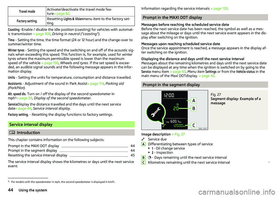
Fig. 27
Segment display: Example of a
message
Image description » Fig. 27
Service due
Differentiating between types of service
▶ - Oil change service
▶ - Inspection
- Days remaining until the next service interval
Kilometres remaining until the next service interval
ABC1)
For models with the speedometer in mph, the second speedometer is displayed in km/h.
44Using the system
Page 106 of 200
The wear and tear on the brake pads is dependent on the operating condi-
tions and driving style. In difficult conditions (e.g. urban, sporty driving), the
condition of the brakes should be checked between services by a specialist ga-
rage.
Brake response can be slower if the brakes are covered in moisture or, in win-
ter, have a layer of ice or salt on them . The brakes should be cleaned and
dried by applying the brakes many times over »
.
Corrosion on the brake discs and dirt on the brake pads can occur if the vehicle
has been parked for a long period and if you do not make much use of the
braking system. The brakes are cleaned by applying the brakes several times
over »
.
Before negotiating a long or steep gradient , reduce speed and shift down a
gear. As a result, the braking effect of the engine will be used, reducing the
load on the brakes. If, nevertheless, there is a need for additional braking, it
should be carried out at intervals.
Emergency braking warning - if it is necessary to brake hard, the system may
cause the brake lights to automatically flash, to alert the traffic behind.
New brake pads must first be “run in” because these do not initially have the
best possible braking effect. Drive especially carefully for the first 200 km or
so.
If the brake fluid level is too low, it can cause faults in the braking system ;
the warning light will light up in the instrument cluster
» page 32,
Braking
system . If the warning light does not light up, yet the stopping distance is per-
ceived to be longer than before, the driving style should be adapted in view of
the unknown cause of the problem, and braking kept to a minimum - seek the
help of a specialist garage without delay.
The brake booster increases the pressure generated with the brake pedal. The
brake booster only operates when the engine is running.
WARNING■ Greater physical effort is required for braking when the engine is switch-
ed off – risk of accident!■
During the braking procedure on a vehicle with manual transmission,
when the vehicle is in gear and at low revs, press the clutch pedal. Other-
wise, the functionality of the brake system may be impaired – risk of acci-
dent!
WARNING (Continued)■ Do not depress the brake pedal if there is no requirement to slow down.
This causes the brakes to overheat and can also result in a longer braking
distance and excessive wear - There is a risk of an accident!■
Only brake for the purpose of drying and cleaning the brake discs if the
traffic conditions permit this. Do not place any other road users in jeopardy.
■
Recommendations for new brake pads should be followed.
■
When stopping and parking, the parking brake should always be applied
firmly, otherwise the vehicle could move off - There is risk of an accident!
■
If a front spoiler, full wheel trim, etc. is mounted retrospectively, it must
be ensured that the air supply to the front wheel brakes is not reduced.
Otherwise, the front brakes could be in danger of overheating – There is
risk of an accident!
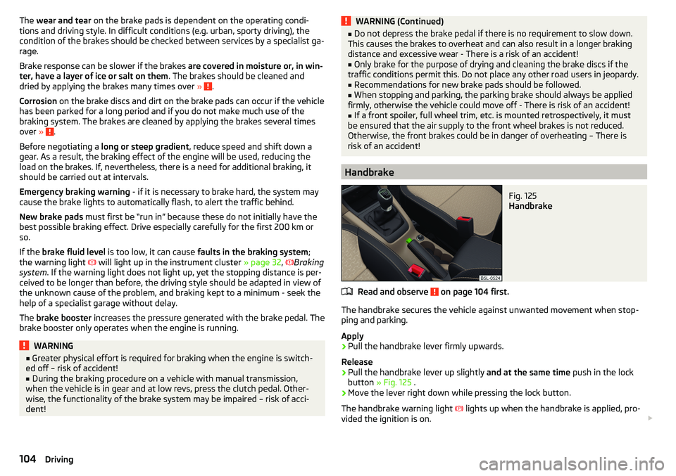
Handbrake
Fig. 125
Handbrake
Read and observe on page 104 first.
The handbrake secures the vehicle against unwanted movement when stop-
ping and parking.
Apply
›
Pull the handbrake lever firmly upwards.
Release
›
Pull the handbrake lever up slightly and at the same time push in the lock
button » Fig. 125 .
›
Move the lever right down while pressing the lock button.
The handbrake warning light
lights up when the handbrake is applied, pro-
vided the ignition is on.
104Driving
Page 115 of 200
The following functions are integrated in the OFF ROAD mode.
▶ Downhill Drive Support » page 113.
▶ TCS OFF ROAD » page 113.
▶ EDL OFF ROAD » page 113.
▶ ABS OFF ROAD » page 113.
▶ Start-Off Assistant » page 114.
Note
If the engine stalls while driving and is started again within 30 seconds, then
OFF ROAD mode will be automatically activated.
Hill Descent Assistant
Read and observe
and on page 112 first.
The hill descent assistant (hereinafter referred to as assistant), with its auto-
matic braking action on all wheels, ensures a constant speed is maintained on
a steep slope when driving forwards and reversing.
During an intervention of the Assistants, the warning light flashes in the in-
strument cluster.
The assistant is automatically engaged under the following conditions. The engine is running.
For vehicles with Manual transmission the shift lever is in the neutral po-
sition and or the 1st, 2nd, 3rd gear, or reverse gear is engaged.
On vehicles with an automatic transmission , the selector lever is in the R,
N, D, S position or in the Tiptronic position.
The downhill gradient is at least 10 % (when driving over sleepers, the lim-
it can briefly drop to 8 %).
Neither the accelerator nor the brake pedal is operated.
Driving speed
Initiate the downhill decent at a reasonable speed up to 30 km / h the hill de-
scent assist maintains this speed when driving downhill constant.
The assistant can maintain constant speed of about 2 - 30 km / h.
If a forwards or reverse gear is engaged for vehicles with Manual transmis-
sion , the speed must be high enough to avoid stalling the engine.
By pressing the accelerator or brake pedal, the speed can be increased or re-
duced. This is true even if the shift lever is in the neutral position and the se-
lector lever in the N position. The engagement of the assistant is resumed af-
ter the pedal is released.WARNINGFor the correct operation of the assistant the road surface must be suffi-
ciently adherent. The assistant cannot properly fulfil its function on slushy
soil due to physical reasons (e.g. ice or mud). - there is a risk of an accident!
Note
During an active intervention of the assistant, the brake lights do not light up.
TCSOFF ROAD
Read and observe
and on page 112 first.
The ASR OFF ROAD makes starting and driving on an unpaved surface easier
as it partially allows wheel-spin.
Note
When disabled, the TCS » page 111 OFF ROAD mode works without the support
of the TCS OFF ROAD.
EDS OFF ROAD
Read and observe
and on page 112 first.
The EDS supports OFF ROAD vehicle traction when driving on a surface withdifferent grip under the drive wheels or when driving over bumps.
A spinning wheel or wheels are braked earlier and with more force than with
the intervention of the standard EDS system.
ABS OFF ROAD
Read and observe
and on page 112 first.
The ABS OFF ROAD supports the driver when braking on an unpaved surface
such as gravel, snow, etc.
The system generated by a controlled locking of the wheels braked wheel be-
fore a “wedge” of piled material, which shortens the braking distance.
113Assist systems
Page 164 of 200

WARNING■Never clamp the jump cable to the negative terminal of the discharged
battery -There is a risk of an explosion.■
The non-insulated parts of the terminal clamps must never touch each
other – risk of short circuit!
■
The jump-start cable connected to the positive terminal of the battery
must not come into contact with electrically conducting parts of the vehicle
– risk of short circuit!
■
Position the jump cables so that they cannot be caught in rotating parts
in the engine compartment - danger of injuries and the risk of vehicle dam-
age.
Towing the vehicle
Information about the towing process
Fig. 179
Braided tow rope / Spiral tow rope
To tow with a tow rope, only use a braided synthetic fibre rope » Fig. 179 -
»
.
Attach the tow rope or the tow bar to the towing eyes at the front
» page 163 , towing eyes at the rear » page 163 or to the towing device of
the trailer device » page 124 .
Conditions for towing. Cars with automatic gearboxes must not be towed with the rear wheels
raised - there is a risk of gearbox damage!
If the gearbox has no oil, your vehicle must be towed with the front axle
raised clear of the ground or on a breakdown vehicle or trailer.
The maximum towing speed is 50 km/h.
The vehicle must be transported on a special breakdown vehicle or trailer
if it is not possible to tow in the vehicle in the way described or if the tow-
ing distance is greater than 50 km.
Driver of the tow vehicle›
On vehicles with manual transmission , engage gear slowly when starting.
›
On vehicles with automatic transmission , accelerate with particular care.
›
Only then approach correctly when the rope is taut.
Driver of the towed vehicle
›
If possible, the vehicle should be towed with the engine running. The brake
booster and power steering only operate if the engine is running, otherwise
much greater force has to be applied to the brake pedal and more power has
to be expended for steering.
›
If it is not possible to start the engine, switch on the ignition so that the
steering wheel does not lock and so that the turn signal lights, windscreen
wipers and windscreen washer system can be used.
›
Take the vehicle out of gear or move the selector lever into position N if the
vehicle is fitted with an automatic gearbox.
›
Keep the tow rope taut at all times during the towing procedure.
WARNING■ Spiral tow ropes must not be used for towing » Fig. 179- , the towing
eye may unscrew out of the vehicle - There is a risk of an accident.■
Ensure tow rope is not twisted - risk of accident.
CAUTION
■ Do not tow-start the engine – There is a risk of damaging the engine. The
battery from another vehicle can be used as a jump-start aid » page 161, Jump-
starting .■
For off-road towing manoeuvres, there is a risk to both vehicles that the fas-
teners may become overloaded and damaged.
Note
We recommend that you use a tow rope from ŠKODA Original Accessories.162Do-it-yourself
Page 190 of 200
LockIndividual settings50
Key48
Locking Central locking button
49
in case of emergency165
KESSY49
Remote control48
Lock steering lock100
Low tyre pressure warning refer to the tyre pressure monitoring
123
Luggage compartment Cover
89
Fastening elements87
Fastening with sliding hook88
Fixing nets87
Flexible storage compartment88
Floor covering on both sides88
Net partition89
Side compartments90
unlock manually165
Unlock the boot lid165
Variable loading floor91
Luggage compartment cover89
Luggage compartment lid52
Luggage Storage86
lighting90
removable lamp90
M
Main beam
59
Warning light37
Manual air conditioning Air distribution control
96
Controls94
Manual gear changing see gear changing
105
Materials defect liability4
MAXI DOT See MAXI DOT display
42
MAXI DOT displayMain menu42
Menu item assist systems43
Menu item Audio43
Menu item navigation42
Menu item phone43
Operation40
Settings43
Mechanical window Open and close
54
Media AUX
77
See Owner's Manual Infotainment6
USB77
Memory42
Memory Function for the seat69
MFD See multifunction display
41
Mirror66
Vanity64
mobility warranty5
Modes of the automatic transmission106
Modifications and technical alterations131
MSR110
Multifunction display Functions
41
Information41
Memory42
Multifunction pocket87
Multifunction steering wheel40
Multimedia holder80
N
N1
91
Nameplate175
Navigation See Owner's Manual Infotainment
6
Net partition89
Nets87
O
OFF ROAD
112
ABS113
EDS113
hill descent assistant113
operation112
Start-Off Assistant114
TCS113
OFF ROAD mode warning light
37
OFF ROAD Mode112
oil See engine oil
145
Oil Information messages
33
Oil changing Engine oil
144
Oil pressure Information messages
33
On-board computer See multifunction display
41
Operating weight176
Original accessories132
Overview Cockpit
27
Engine compartment144
Fuses167
Warning lights31
P
Park assist Departing from a parallel parking space
120
Parking120
Park Assist118
Automatic brake assist121
Malfunctions121
Operation118
Parking space search119
188Index