display SMART FORTWO COUPE 2011 User Guide
[x] Cancel search | Manufacturer: SMART, Model Year: 2011, Model line: FORTWO COUPE, Model: SMART FORTWO COUPE 2011Pages: 228, PDF Size: 11.48 MB
Page 87 of 228
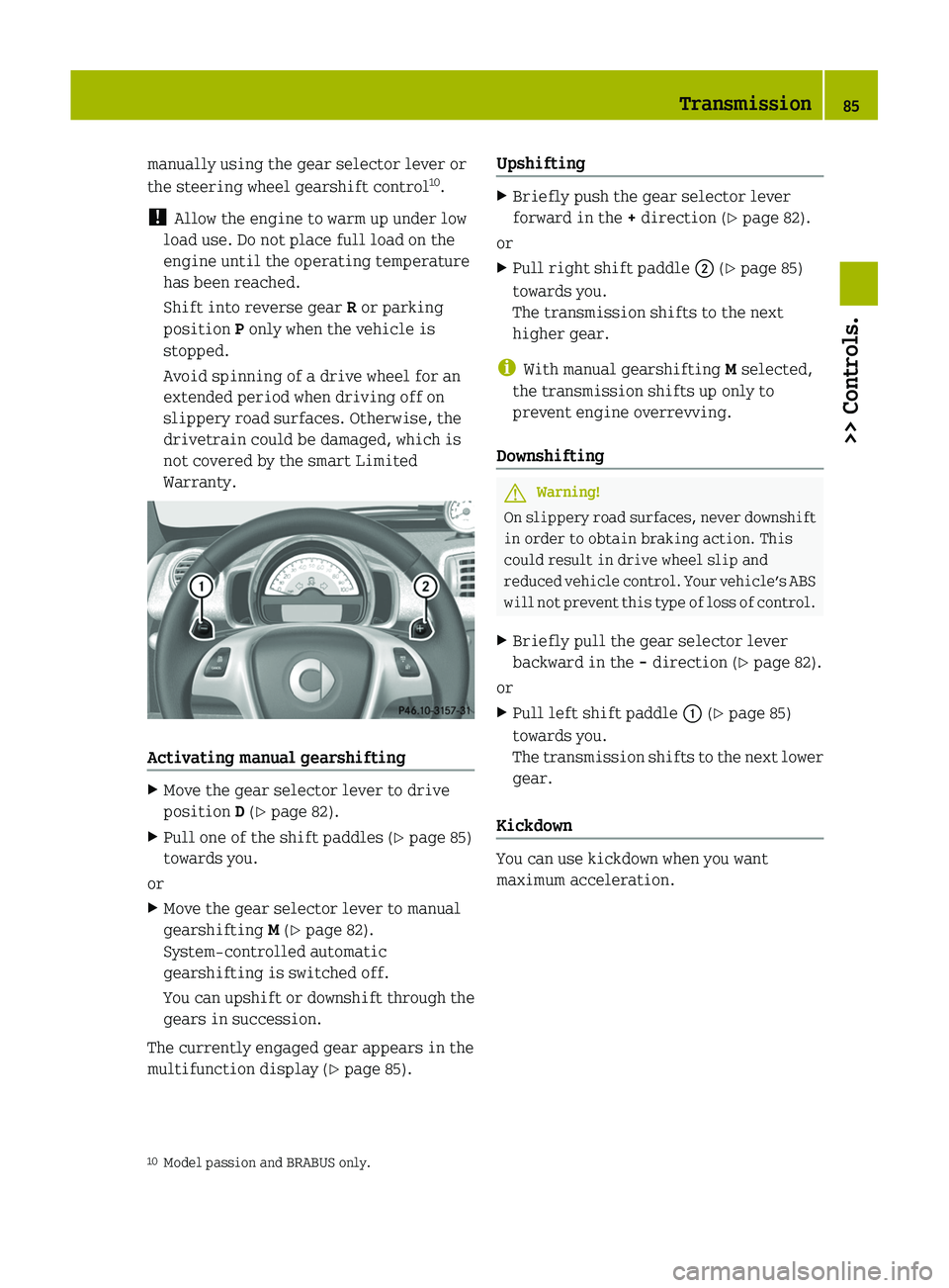
manually using the gear selector lever or
the steering wheel gearshift control 10
.
! Allow the engine to warm up under low
load use. Do not place full load on the
engine until the operating temperature
has been reached.
Shift into reverse gear R or parking
position P only when the vehicle is
stopped.
Avoid spinning of a drive wheel for an
extended period when driving off on
slippery road surfaces. Otherwise, the
drivetrain could be damaged, which is
not covered by the smart Limited
Warranty.
Activating manual gearshifting
XMove the gear selector lever to drive
position D ( Y page 82).XPull one of the shift paddles ( Y page 85)
towards you.
or
XMove the gear selector lever to manual
gearshifting M (Y page 82).
System-controlled automatic
gearshifting is switched off.
You can upshift or downshift through the
gears in succession.
The currently engaged gear appears in the
multifunction display ( Y page 85).
UpshiftingXBriefly push the gear selector lever
forward in the + direction ( Y page 82).
or
XPull right shift paddle 0047 (Y page 85)
towards you.
The transmission shifts to the next
higher gear.
i With manual gearshifting M selected,
the transmission shifts up only to
prevent engine overrevving.
Downshifting
GWarning!
On slippery road surfaces, never downshift
in order to obtain braking action. This
could result in drive wheel slip and
reduced vehicle control. Your vehicle’s ABS
will not prevent this type of loss of control.
XBriefly pull the gear selector lever
backward in the - direction ( Y page 82).
or
XPull left shift paddle 0046 (Y page 85)
towards you.
The transmission shifts to the next lower
gear.
Kickdown
You can use kickdown when you want
maximum acceleration.
10 Model passion and BRABUS only.Transmission85>> Controls.BA 451 USA, CA Edition A 2011; 1; 4, en-UShereepeVersion: 3.0.3.62010-05-11T15:12:26+02:00 - Seite 85Z
Page 88 of 228
XPress the accelerator pedal past the
point of resistance.
Depending on the engine speed the
transmission shifts into a lower gear.XWhen you have reached the desired speed,
briefly push the gear selector lever
forward in the + direction ( Y page 82).
or
XPull right shift paddle 0047 (Y page 85)
towards you.
The transmission shifts to the next
higher gear.
Deactivating manual gearshifting
XWith drive position D selected: Pull and
hold right shift paddle 0047 (Y page 85)
towards you for longer than two seconds.
or
XWith manual gearshifting M selected:
Move the gear selector lever to drive
position D ( Y page 82).
System-controlled automatic
gearshifting is switched on again.
Emergency operation (limp-home
mode)
In this mode only a certain gear or a
certain gear combination can be selected.
This mode is triggered in case of
transmission malfunctions and enables you
driving to the nearest workshop such as a
smart center.
If vehicle acceleration becomes less
responsive or sluggish or the transmission
no longer shifts, the transmission is most
likely operating in limp-home (emergency
operation) mode. The transmission
position indicator flashes and the ¬
symbol appears in the multifunction
display.
Driving in limp-home mode:XMove the gear selector lever to drive
position D ( Y page 82).XContinue to drive.XHave the transmission checked at an
authorized smart center as soon as
possible.
i It is possible that a gear combination
including the reverse gear can not be
selected. Keep in mind when parking,
that reversing the vehicle might be
impossible.
In case of a minor transmission
malfunction, it might be possible to teach-
in the transmission in order to restore the
normal transmission mode.
i If the attempt to teach-in the
transmission fails, you cannot continue
to drive. Therefore we strongly
recommend that you have the
transmission taught-in at a qualified
workshop or at an authorized smart
center.
Teaching-in the transmission system:
XStop the vehicle in a safe location.XMove the gear selector lever to park
position P.XTurn off the engine.XWait at least 30 seconds before
restarting.XPress the brake pedal.XRestart the engine
Three bars instead of P appear in the
multifunction display.XWait at least 30 seconds.
The transmission is taught in.
When teaching-in was successful: P
appears in the multifunction display again
and normal transmission operating is
restored.
XContinue to drive.86Transmission>> Controls.
BA 451 USA, CA Edition A 2011; 1; 4, en-UShereepeVersion: 3.0.3.62010-05-11T15:12:26+02:00 - Seite 86
Page 89 of 228
After an unsuccessful teaching-in: Three
bars instead of P appear in the
multifunction display.XDo not continue to drive.XTurn off the engine.XEngage the parking brake when leaving
the vehicle.XContact Roadside Assistance or an
authorized smart center.
Instrument cluster
Multifunction display
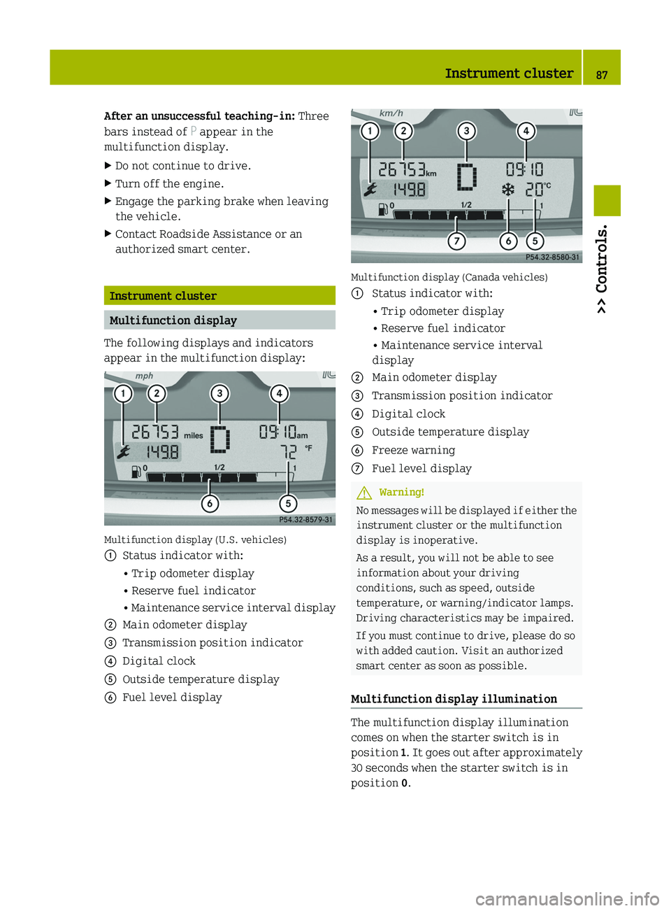
The following displays and indicators
appear in the multifunction display:
Multifunction display (U.S. vehicles)
0046Status indicator with:• Trip odometer display• Reserve fuel indicator• Maintenance service interval display0047Main odometer display008ATransmission position indicator0088Digital clock0086Outside temperature display0087Fuel level display
Multifunction display (Canada vehicles)
0046 Status indicator with:• Trip odometer display• Reserve fuel indicator• Maintenance service interval
display0047Main odometer display008ATransmission position indicator0088Digital clock0086Outside temperature display0087Freeze warning006EFuel level displayGWarning!
No messages will be displayed if either the
instrument cluster or the multifunction
display is inoperative.
As a result, you will not be able to see
information about your driving
conditions, such as speed, outside
temperature, or warning/indicator lamps.
Driving characteristics may be impaired.
If you must continue to drive, please do so
with added caution. Visit an authorized
smart center as soon as possible.
Multifunction display illumination
The multifunction display illumination
comes on when the starter switch is in
position 1. It goes out after approximately
30 seconds when the starter switch is in
position 0.
Instrument cluster87>> Controls.BA 451 USA, CA Edition A 2011; 1; 4, en-UShereepeVersion: 3.0.3.62010-05-11T15:12:26+02:00 - Seite 87Z
Page 90 of 228
For adjusting the multifunction display
illumination, see “Adjusting instrument
cluster illumination” ( Y page 93).
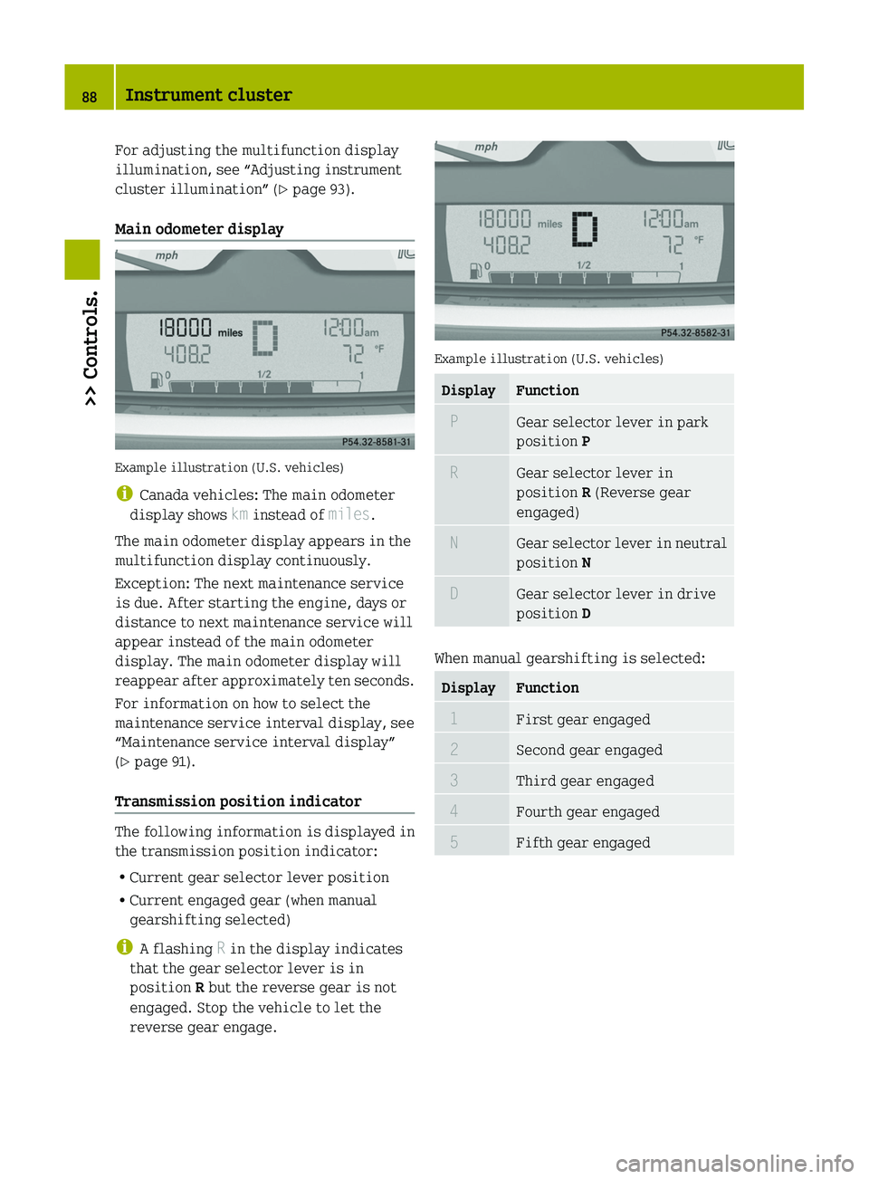
Main odometer display
Example illustration (U.S. vehicles)
i Canada vehicles: The main odometer
display shows km instead of miles.
The main odometer display appears in the
multifunction display continuously.
Exception: The next maintenance service
is due. After starting the engine, days or
distance to next maintenance service will
appear instead of the main odometer
display. The main odometer display will
reappear after approximately ten seconds.
For information on how to select the
maintenance service interval display, see
“Maintenance service interval display”
( Y page 91).
Transmission position indicator
The following information is displayed in
the transmission position indicator:
R Current gear selector lever position
R Current engaged gear (when manual
gearshifting selected)
i A flashing R in the display indicates
that the gear selector lever is in
position R but the reverse gear is not
engaged. Stop the vehicle to let the
reverse gear engage.
Example illustration (U.S. vehicles)
DisplayFunction PGear selector lever in park
position P RGear selector lever in
position R (Reverse gear
engaged) NGear selector lever in neutral
position N DGear selector lever in drive
position D
When manual gearshifting is selected:
DisplayFunction 1First gear engaged 2Second gear engaged 3Third gear engaged 4Fourth gear engaged 5Fifth gear engaged88Instrument cluster>> Controls.
BA 451 USA, CA Edition A 2011; 1; 4, en-UShereepeVersion: 3.0.3.62010-05-11T15:12:26+02:00 - Seite 88
Page 91 of 228
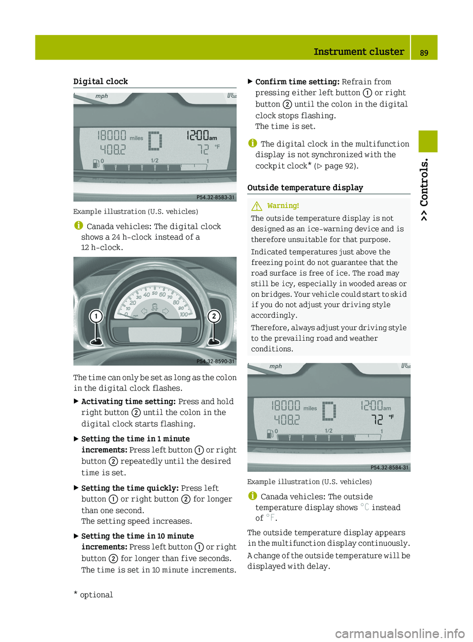
Digital clock
Example illustration (U.S. vehicles)
i Canada vehicles: The digital clock
shows a 24 h-clock instead of a
12 h-clock.
The time can only be set as long as the colon
in the digital clock flashes.
XActivating time setting: Press and hold
right button 0047 until the colon in the
digital clock starts flashing.XSetting the time in 1 minute
increments: Press left button 0046 or right
button 0047 repeatedly until the desired
time is set.XSetting the time quickly: Press left
button 0046 or right button 0047 for longer
than one second.
The setting speed increases.XSetting the time in 10 minute
increments: Press left button 0046 or right
button 0047 for longer than five seconds.
The time is set in 10 minute increments.XConfirm time setting: Refrain from
pressing either left button 0046 or right
button 0047 until the colon in the digital
clock stops flashing.
The time is set.
i The digital clock in the multifunction
display is not synchronized with the
cockpit clock* ( Y page 92).
Outside temperature display
GWarning!
The outside temperature display is not
designed as an ice-warning device and is
therefore unsuitable for that purpose.
Indicated temperatures just above the
freezing point do not guarantee that the
road surface is free of ice. The road may
still be icy, especially in wooded areas or
on bridges. Your vehicle could start to skid
if you do not adjust your driving style
accordingly.
Therefore, always adjust your driving style
to the prevailing road and weather
conditions.
Example illustration (U.S. vehicles)
i Canada vehicles: The outside
temperature display shows °C instead
of °F.
The outside temperature display appears
in the multifunction display continuously.
A change of the outside temperature will be
displayed with delay.
Instrument cluster89>> Controls.* optionalBA 451 USA, CA Edition A 2011; 1; 4, en-UShereepeVersion: 3.0.3.62010-05-11T15:12:26+02:00 - Seite 89Z
Page 92 of 228
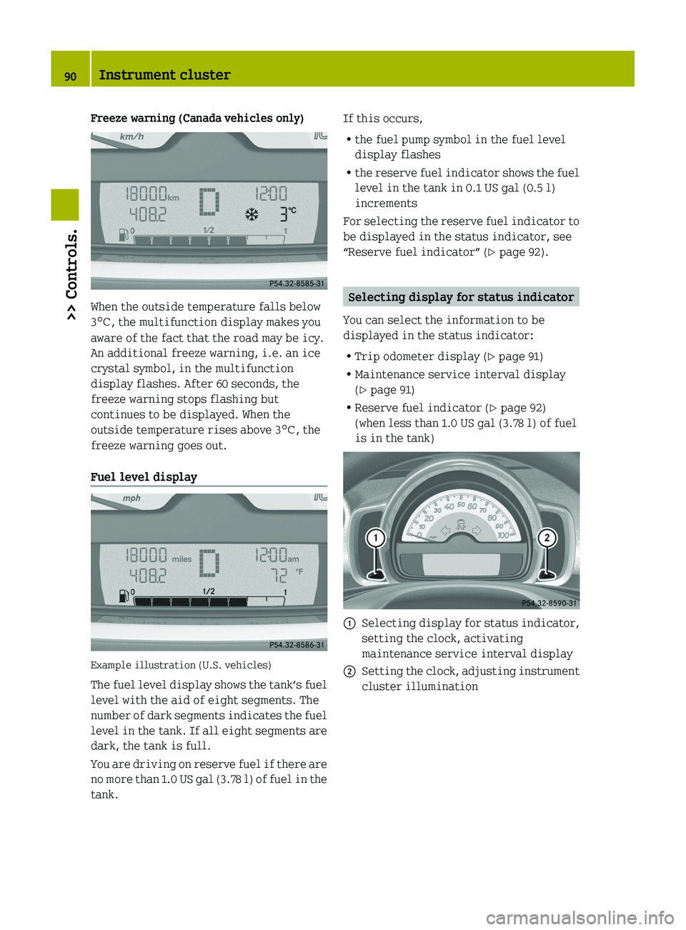
Freeze warning (Canada vehicles only)
When the outside temperature falls below
3 ¥ , the multifunction display makes you
aware of the fact that the road may be icy.
An additional freeze warning, i.e. an ice
crystal symbol, in the multifunction
display flashes. After 60 seconds, the
freeze warning stops flashing but
continues to be displayed. When the
outside temperature rises above 3 ¥, the
freeze warning goes out.
Fuel level display
Example illustration (U.S. vehicles)
The fuel level display shows the tank’s fuel
level with the aid of eight segments. The
number of dark segments indicates the fuel
level in the tank. If all eight segments are
dark, the tank is full.
You are driving on reserve fuel if there are
no more than 1.0 US gal (3.78 l) of fuel in the
tank.
If this occurs,
R the fuel pump symbol in the fuel level
display flashes
R the reserve fuel indicator shows the fuel
level in the tank in 0.1 US gal (0.5 l)
increments
For selecting the reserve fuel indicator to
be displayed in the status indicator, see
“Reserve fuel indicator” ( Y page 92).
Selecting display for status indicator
You can select the information to be
displayed in the status indicator:
R Trip odometer display ( Y page 91)
R Maintenance service interval display
( Y page 91)
R Reserve fuel indicator ( Y page 92)
(when less than 1.0 US gal (3.78 l) of fuel
is in the tank)
0046Selecting display for status indicator,
setting the clock, activating
maintenance service interval display0047Setting the clock, adjusting instrument
cluster illumination90Instrument cluster>> Controls.
BA 451 USA, CA Edition A 2011; 1; 4, en-UShereepeVersion: 3.0.3.62010-05-11T15:12:26+02:00 - Seite 90
Page 93 of 228
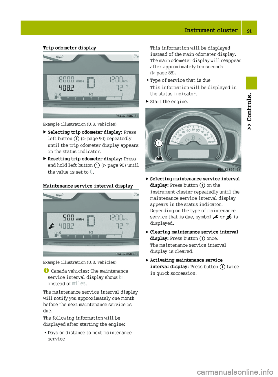
Trip odometer display
Example illustration (U.S. vehicles)
XSelecting trip odometer display: Press
left button 0046 (Y page 90) repeatedly
until the trip odometer display appears
in the status indicator.XResetting trip odometer display: Press
and hold left button 0046 (Y page 90) until
the value is set to 0.
Maintenance service interval display
Example illustration (U.S. vehicles)
i Canada vehicles: The maintenance
service interval display shows km
instead of miles.
The maintenance service interval display
will notify you approximately one month
before the next maintenance service is
due.
The following information will be
displayed after starting the engine:
R Days or distance to next maintenance
service
This information will be displayed
instead of the main odometer display.
The main odometer display will reappear
after approximately ten seconds
( Y page 88).
R Type of service that is due
This information will be displayed in
the status indicator.XStart the engine.XSelecting maintenance service interval
display: Press button 0046 on the
instrument cluster repeatedly until the
maintenance service interval display
appears in the status indicator.
Depending on the type of maintenance
service that is due, symbol ¬ or } is
displayed.XClearing maintenance service interval
display: Press button 0046 once.
The maintenance service interval
display is cleared.XActivating maintenance service
interval display: Press button 0046 twice
in quick succession.Instrument cluster91>> Controls.BA 451 USA, CA Edition A 2011; 1; 4, en-UShereepeVersion: 3.0.3.62010-05-11T15:12:26+02:00 - Seite 91Z
Page 94 of 228
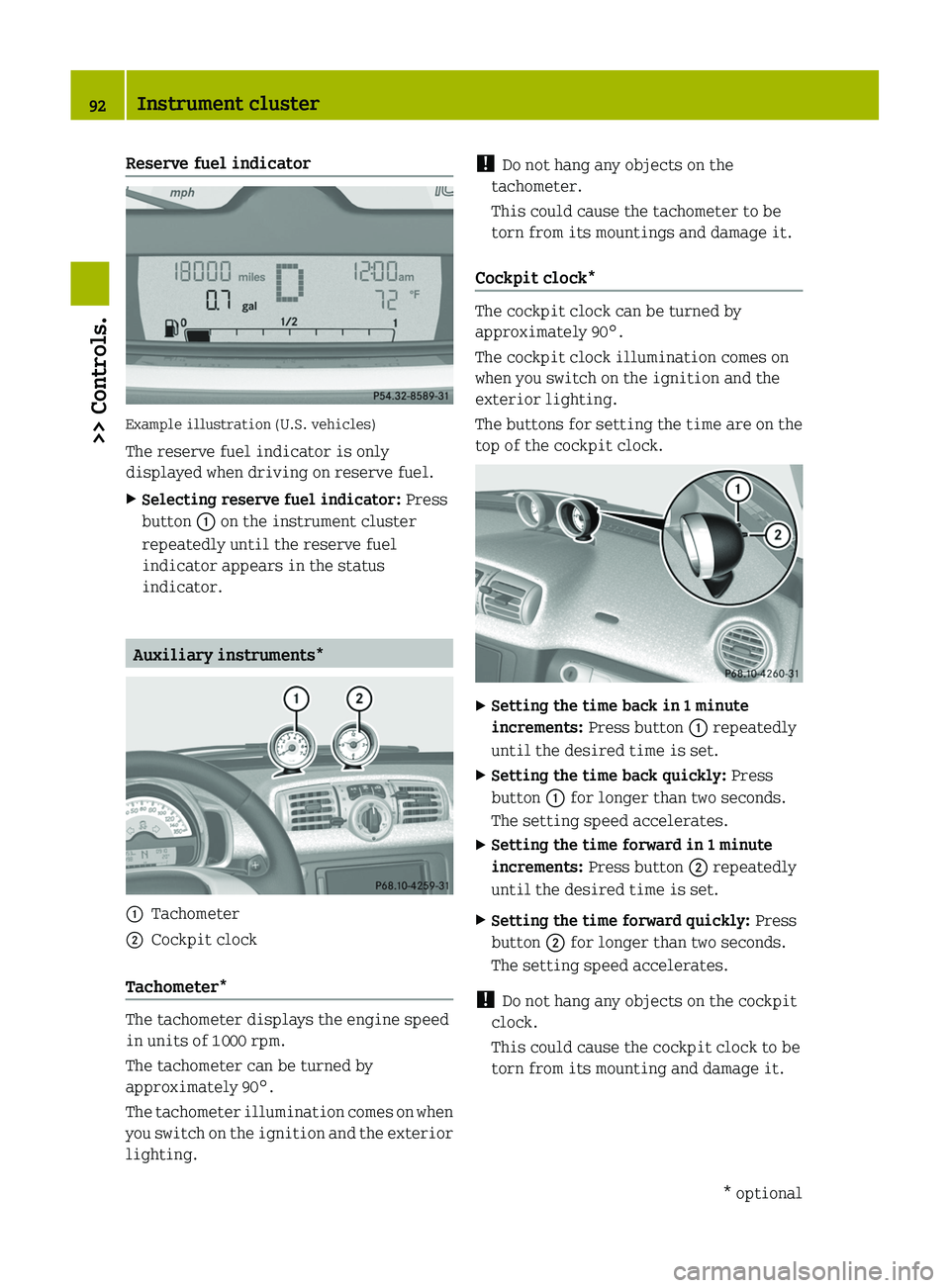
Reserve fuel indicator
Example illustration (U.S. vehicles)
The reserve fuel indicator is only
displayed when driving on reserve fuel.
XSelecting reserve fuel indicator: Press
button \000F on the instrument cluster
repeatedly until the reserve fuel
indicator appears in the status
indicator.
Auxiliary instruments*
\000FTachometer\000GCockpit clock
Tachometer*
The tachometer displays the engine speed
in units of 1 000 rpm.
The tachometer can be turned by
approximately 90°.
The tachometer illumination comes on when
you switch on the ignition and the exterior
lighting.
! Do not hang any objects on the
tachometer.
This could cause the tachometer to be
torn from its mountings and damage it.
Cockpit clock*
The cockpit clock can be turned by
approximately 90°.
The cockpit clock illumination comes on
when you switch on the ignition and the
exterior lighting.
The buttons for setting the time are on the
top of the cockpit clock.
XSetting the time back in 1 minute
increments: Press button \000F repeatedly
until the desired time is set.
XSetting the time back quickly: Press
button \000F for longer than two seconds.
The setting speed accelerates.
XSetting the time forward in 1 minute
increments: Press button \000G repeatedly
until the desired time is set.
XSetting the time forward quickly: Press
button \000G for longer than two seconds.
The setting speed accelerates.
! Do not hang any objects on the cockpit
clock.
This could cause the cockpit clock to be
torn from its mounting and damage it.
92Instrument cluster>> Controls.* optionalBA 451 USA, CA Edition A 2011; 1; 4, en-UShereepeVersion: 3.0.3.62010-05-11T15:12:26+02:00 - Seite 92
Page 95 of 228
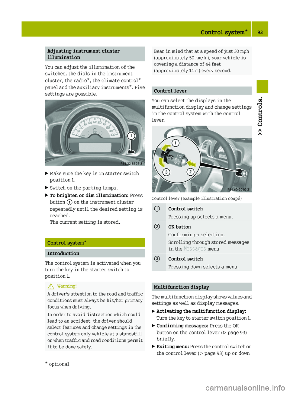
Adjusting instrument cluster
illumination
You can adjust the illumination of the
switches, the dials in the instrument
cluster, the radio*, the climate control*
panel and the auxiliary instruments*. Five
settings are possible.
XMake sure the key is in starter switch
position 1.
XSwitch on the parking lamps.XTo brighten or dim illumination: Press
button \000F on the instrument cluster
repeatedly until the desired setting is
reached.
The current setting is stored.
Control system*
Introduction
The control system is activated when you
turn the key in the starter switch to
position 1.
GWarning!
A driver’s attention to the road and traffic
conditions must always be his/her primary
focus when driving.
In order to avoid distraction which could
lead to an accident, the driver should
select features and change settings in the
control system only vehicle at a standstill
or when traffic and road conditions permit
it to be done safely.
Bear in mind that at a speed of just 30 mph
(approximately 50 km/h ), your vehicle is
covering a distance of 44 feet
(approximately 14 m) every second.
Control lever
You can select the displays in the
multifunction display and change settings
in the control system with the control
lever.
Control lever (example illustration coupé)
\000FControl switch
Pressing up selects a menu.
\000GOK button
Confirming a selection.
Scrolling through stored messages
in the Messages menu
\000
Page 96 of 228
until the message Back appears in the
multifunction display.XPress the OK button on the control lever
briefly.94Control system*>> Controls.* optionalBA 451 USA, CA Edition A 2011; 1; 4, en-UShereepeVersion: 3.0.3.62010-05-11T15:12:26+02:00 - Seite 94