steering wheel SMART FORTWO COUPE 2014 User Guide
[x] Cancel search | Manufacturer: SMART, Model Year: 2014, Model line: FORTWO COUPE, Model: SMART FORTWO COUPE 2014Pages: 222, PDF Size: 16.17 MB
Page 79 of 222
appears in the multifunction display
(Y
page 87).
The pointer of the power gauge moves
from "OFF“ to "0“ (Y page 81).Driving
i The vehicle has a crawler function. The
vehicle moves forward when the brake
pedal is released.
X Depress the brake pedal.
X Move the gear selector lever to drive
position D.
D D appears in the transmission position
indicator.
X Release the brake pedal.
The vehicle moves forward.
X Depress the accelerator pedal smoothly.
The vehicle accelerates. Reversing the vehicle
! Shift the transmission into reverse
gear Ronly when the vehicle is stopped
in order to avoid damaging the trans-
mission.
You can drive in reverse gear at a speed
of up to 9 mph (15 km/h).
i The vehicle has a crawler function.
Thevehicle moves forward when the
brakepedal is released.
X Depress the brake pedal.
X Move the gear selector lever to reverse
gear R.
R R appears in the transmission position
indicator.
X Release the brake pedal.
The vehicle moves forward.
X Depress the accelerator pedal smoothly.
The vehicle accelerates. Parking
G
WARNING
With the drive system inactive, there is no
power assistance for the brake and steering
systems. In this case, it is important to
keep in mind that a considerably higher
degree of effort is necessary to brake and
steer the vehicle. Adapt your driving
accordingly. G
WARNING
Vehicle movement can cause serious per-
sonal injury. Therefore, always do the fol-
lowing before exiting and leaving the
vehicle:
R Keep right foot on the brake pedal.
R Engage the parking brake.
R Move the gear selector lever to park
position P.
R Slowly release the brake pedal.
R When parked on an incline, always turn
the front wheels towards the curb.
R Turn the key to starter switch position 0
and remove the key from the starter
switch.
R Take the key with you and lock the vehicle
when leaving.
X Properly stop and park the vehicle.
X Depress the brake pedal.
X Engage the parking brake (Y page 77).
When the ignition is switched on, the
brake warning lamp 0027(USA only) or
004D (Canada only) in the instrument
cluster comes on.
X Release the brake pedal.
Parking brake The parking brake serves to secure the
vehicle against rolling away when it is
stationary or parked. Driving and parking
77>> Controls. Z
Page 81 of 222

Make sure the drive system is active when-
ever the vehicle is rolling. Have the brake
system repaired at an authorized electric
drive smart center, if there is a fault in the
brake system. If a brake circuit has failed (Y
page 167),
you must depress brake pedal 0043further
down to achieve the same effect and the
braking distance is increased.
i The brake servo will only function with
the ignition switched on. Switching off the drive system
G
WARNING
Do not turn off the drive system before the
vehicle has come to a complete stop. With
the drive system not running, there is no
power assistance for the brake and steering
systems. In this case, it is important to
keep in mind that a considerably higher
degree of effort is necessary to brake and
steer the vehicle.
X Depress the brake pedal.
X Move the gear selector lever to park
position P.
The transmission position indicator
should be on P P
! Always engage the parking brake in
addition to shifting to park position P.X
Release the brake pedal.
X Turn the key to starter switch position
0.
X Remove the key from the starter switch.
The electronic immobilizer is acti-
vated. Transmission
Shifting procedure
Gearshift pattern for transmission
005D
Park position
005E
Reverse gear
005C
Neutral position
005B
Drive position
Select a gear:
X
Switch on the ignition.
X Depress the brake pedal.
X Move the gear selector lever to the
desired position. Steering wheel paddle shifters* (for
recuperation)
G
WARNING
The operating condition of the high-volt-
age battery (e.g. not yet at normal operat-
ing temperature or fully charged) influen- Transmission
79>> Controls.
* optional Z
Page 82 of 222

ces the braking effect of the electric
motor.
In overrun or braking mode, the motor's
braking effect may therefore be reduced or
may not be present at all.
As a result of the reduced engine braking
effect, you may cause an accident and
injure yourself or others.
Compensate for the reduced engine braking
effect by pressing the brake pedal accord-
ingly, as required.
Using the steering wheel paddle shifters *,
you can increase or decrease the recuper-
ation in overrun phases. Recuperation
takes place when you release the acceler-
ator pedal. The electric motor will then be
used as a generator and energy will be
regained while driving. The regained
energy is stored in the high-voltage bat-
tery. High recuperation decelerates your
vehicle stronger.
In overrun phases, there are three levels of
recuperation:
R no recuperation (level 0, coasting)
R moderate recuperation (level 1)
R high-level recuperation (level 2)
The amount of recuperation in overrun
mode is displayed in the power gauge
(Y page 81).
The set mode for recuperation is shown in
the recuperation display (Y page 84).
When you switch on the ignition, level 1 is
automatically preset. 0043
Left steering wheel paddle shifter
(minus)
0044 Right steering wheel paddle shifter
(plus)
X Decrease recuperation: Pull left steer-
ing wheel paddle shifter 0043.
X Increase recuperation: Pull right steer-
ing wheel paddle shifter 0044.
Use the different levels 0 to 2 for condi-
tions as described below: Level 0 Driving without frequent
breaking. No sharp bends on
the road ahead.
Maximum kinetic energy
remains for the vehicle.
Level 1 Normal driving, standard set-
ting.
Level 2 Sporty driving.
The break pedal has to be
depressed less often, as the
deceleration due to recuper-
ation is higher than in
level 1.
The energy efficiency is sub-
stantially higher than if the
vehicle is decelerated by
depressing the brake pedal.
At levels 1 and 2 the vehicle can be step-
lessly decelerated by depressing the brake
pedal.80
Transmission>> Controls.
* optional
Page 99 of 222

0043
USB socket
0044 AUX socket smart surround sound system*
The smart surround sound system supple-
ments the existing speakers with more
powerful and additional speakers (includ-
ing a digital amplifier in the passenger
footwell and a passive subwoofer). Driving systems
Cruise control*
The cruise control maintains the speed you
set for your vehicle automatically. On
downhill grades, the cruise control does
not brake the vehicle via the brake system.
The cruise control can only use the braking
power of the engine. You must apply the
brakes yourself in order to reduce the
vehicle speed. The cruise control will then
be canceled. G
WARNING
The cruise control is a convenience system
designed to assist the driver during vehi-
cle operation. The cruise control cannot
take road, traffic, and weather conditions
into account. The driver is and must always
remain responsible for the vehicle’s speed
and for safe brake operation. Do not use the cruise control
R
if the road, traffic, and weather condi-
tions do not make it advisable to travel
at a constant speed
R on slippery roads
Rapid changes in tire traction can result
in wheel spin and loss of control.
R when driving in fog
The use of the cruise control is recom-
mended for driving at a constant speed for
extended periods of time.
With the cruise control is activated and a
speed set, the following message appears
in the multifunction display: U.S. vehicles
0043
Cruise control activated
0044 Set speed Canada vehicles
0043
Cruise control activated
0044 Set speed
The cruise control is operated via buttons
on the steering wheel. Driving systems
97>> Controls.
* optional Z
Page 108 of 222

Storage compartments
G
WARNING
To help avoid personal injury during a col-
lision or sudden maneuver, exercise care
when storing objects in the vehicle. Put
luggage or cargo in the cargo compartment
if possible. Do not pile luggage or cargo
higher than the seat backrests.
Keep compartment lids closed. This will
help to prevent stored objects from being
thrown about and injuring vehicle occu-
pants during
R hard braking
R a change of direction
R an accident
Do not store objects under the driver’s seat.
Objects stored under the driver’s seat can
slide forward into driver’s foot well during
braking and get caught between or beneath
the pedals. This could restrict your ability
to brake or accelerate and could lead to
accidents and injury.
Coin holder The coin holder is located in front of the
gear selector lever. Example illustration (coupé)
0043 Coin holder
Door pockets The door pockets are located in the driver’s
and passenger door. 0043
Door pocket
Storage trays next to the steering wheel The storage trays are located to the left and
right of the steering wheel. 0043
Storage tray
Glove box i
A clamp rail for slips of paper is
located on the outside of the glove box
lid. 106
Loading and storing>> Controls.
Page 131 of 222
ride comfort, wear unevenly, increase
stopping distance, and result in sudden
deflation (blowout) because they are more
likely to become punctured or damaged by
road debris, potholes etc.
Do not overload the tires by exceeding the
specified load limit as indicated on the
Tire and Loading Information placard on
the driver’s door B‑pillar. Overloading the
tires can overheat them, possibly causing
a blowout. Overloading the tires can also
result in handling or steering problems, or
brake failure.
Your vehicle is equipped with the Tire and
Loading Information placard located on
the driver’s door B‑pillar (Y page 134).
The tire inflation pressure should be
checked regularly. Only adjust the tire
inflation pressure on cold tires. The tires
can be considered cold if the vehicle has
been parked for at least 3 hours or driven
less than 1 mile (1.6 km). Depending on the
ambient temperature, the driving speed
and the tire load, the tire temperature
changes. When the tire temperature
changes by 18¦ (10¥), the tire inflation
pressure will change by approximately
10 kpa (0.1 bar, 1.5 psi). Keep this in mind
when checking tire inflation pressure on
warm tires and adjust the tire pressure
only if the tire inflation pressure is too
low for the current operating conditions.
If you check the tire inflation pressure
when the tires are warm, the reading will
be higher than the cold reading. This is
normal. Do not let air out to match the
specified cold tire inflation pressure.
Otherwise, the tire will be underinflated.
Follow recommended cold tire inflation
pressures listed on Tire and Loading
Information placard on the driver’s door
B‑pillar.
Keeping the tires properly inflated pro-
vides the best handling, tread life and rid-
ing comfort. In addition to the Tire and Loading Infor-
mation placard on the driver’s door B‑pil-
lar, also consult the tire inflation pres-
sure label (if available) on the inside of
the filler flap for any additional informa-
tion pertaining to special driving situa-
tions. For more information, see “Impor-
tant notes on tire inflation pressure”
(Y
page 129).
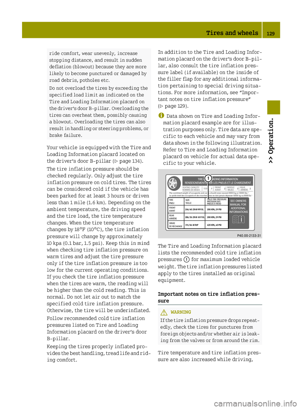
i Data shown on Tire and Loading Infor-
mation placard example are for illus-
tration purposes only. Tire data are spe-
cific to each vehicle and may vary from
data shown in the following illustration.
Refer to Tire and Loading Information
placard on vehicle for actual data spe-
cific to your vehicle. The Tire and Loading Information placard
lists the recommended cold tire inflation
pressures
0043for maximum loaded vehicle
weight. The tire inflation pressures listed
apply to the tires installed as original
equipment.
Important notes on tire inflation pres-
sure G
WARNING
If the tire inflation pressure drops repeat-
edly, check the tires for punctures from
foreign objects and/or whether air is leak-
ing from the valves or from around the rim.
Tire temperature and tire inflation pres-
sure are also increased while driving, Tires and wheels
129>> Operation. Z
Page 132 of 222
depending on the driving speed and the
tire load.
Potential problems associated with
underinflated and overinflated tires Underinflated tires
G
WARNING
Follow recommended tire inflation pres-
sures.
Do not underinflate tires. Underinflated
tires wear excessively and/or unevenly,
adversely affect handling and energy con-
sumption of the vehicle, and are more
likely to fail from being overheated.
Underinflated tires can
R cause excessive and uneven tire wear
R adversely affect energy consumption of
the vehicle
R lead to tire failure from being over-
heated
R adversely affect handling characteris-
tics
Overinflated tires G
WARNING
Follow recommended tire inflation pres-
sures.
Do not overinflate tires. Overinflated
tires can adversely affect handling and
ride comfort, wear unevenly, increase
stopping distance, and result in sudden
deflation (blowout) because they are more
likely to become punctured or damaged by
road debris, potholes etc.
Overinflated tires can
R adversely affect handling characteris-
tics
R cause uneven tire wear
R be more prone to damage from road haz-
ards
R adversely affect ride comfort
R increase stopping distance Checking tire inflation pressure
Safety notes G
WARNING
Follow recommended tire inflation pres-
sures.
Do not underinflate tires. Underinflated
tires wear excessively and/or unevenly,
adversely affect handling and energy con-
sumption of the vehicle, and are more
likely to fail from being overheated.
Do not overinflate tires. Overinflated
tires can adversely affect handling and
ride comfort, wear unevenly, increase
stopping distance, and result in sudden
deflation (blowout) because they are more
likely to become punctured or damaged by
road debris, potholes etc.
Do not overload the tires by exceeding the
specified load limit as indicated on the
Tire and Loading Information placard on
the driver’s door B‑pillar. Overloading the
tires can overheat them, possibly causing
a blowout. Overloading the tires can also
result in handling or steering problems, or
brake failure.
Check the tire inflation pressure at least
once a month.
Check and adjust the tire inflation pres-
sure when the tires are cold (Y page 129).
Checking tire inflation pressure man-
ually Follow the steps below to achieve correct
tire inflation pressure:
X Remove the cap from the valve on one tire.
X Firmly press a tire gauge onto the valve.
X Read the tire inflation pressure on tire
gauge and check against the recom-
mended tire inflation pressure on the
Tire and Loading Information placard on
the driver’s door B‑pillar (Y page 134).
If necessary, add air to achieve the rec-
ommended tire inflation pressure. 130
Tires and wheels>> Operation.
Page 133 of 222
X
If you have overfilled the tire, release
tire inflation pressure by pushing the
metal stem of the valve with e.g. a tip of
a pen. Then recheck the tire inflation
pressure with the tire gauge.
X Install the valve cap.
X Repeat this procedure for each tire.
Tire Pressure Monitoring System
(TPMS)* Your vehicle may be equipped with a
Tire
Pressure Monitoring System (TPMS).
It monitors the tire inflation pressure in
all four tires. A warning is issued to alert
you to a decrease in pressure in one or more
of the tires.
The Tire Pressure Monitoring System
(TPMS) is equipped with a combination low
tire pressure/TPMS malfunction telltale in
the instrument cluster. Depending on how
the telltale illuminates, it indicates a low
tire pressure condition or a malfunction in
the TPMS system itself:
R If the telltale illuminates continuously,
one or more of your tires is significantly
underinflated. There is no malfunction
in the TPMS.
R If the telltale flashes for 60 seconds and
then stays illuminated, the TPMS system
itself is not operating properly.
The TPMS only functions on wheels that are
equipped with the proper electronic sen-
sors. G
WARNING
The TPMS does not indicate a warning for
wrongly selected inflation pressures.
Always adjust tire inflation pressure
according to the Tire and Loading Infor-
mation placard on the driver’s door B‑pil-
lar.
The TPMS is not able to issue a warning due
to a sudden dramatic loss of pressure (e.g.
tire blowout caused by a foreign object). In
this case bring the vehicle to a halt by carefully applying the brakes and avoiding
abrupt steering maneuvers.
G
WARNING
Each tire should be checked monthly when
cold and inflated to the inflation pressure
recommended by the vehicle manufacturer
on the Tire and Loading Information plac-
ard. If your vehicle has tires of a different
size than the size indicated on the Tire and
Loading Information placard, you should
determine the proper tire inflation pres-
sure for those tires.
As an added safety feature, your vehicle has
been equipped with a tire pressure moni-
toring system (TPMS) that illuminates a low
tire pressure telltale when one or more of
your tires is significantly underinflated.
Accordingly, when the low tire pressure
telltale illuminates, you should stop and
check your tires as soon as possible, and
inflate them to the proper pressure. Driv-
ing on a significantly underinflated tire
causes the tire to overheat and can lead to
tire failure.
Underinflation also increases energy con-
sumption, reduces tire tread life, and may
affect the vehicle’s handling and stopping
ability. Please note that the TPMS is not a
substitute for proper tire maintenance,
and it is the driver’s responsibility to
maintain correct tire pressure, even if
underinflation has not reached the level to
trigger illumination of the TPMS low tire
pressure telltale.
Your vehicle has also been equipped with a
TPMS malfunction indicator to indicate
when the system is not operating properly.
The TPMS malfunction indicator is com-
bined with the low tire pressure telltale.
When the system detects a malfunction, the
telltale will flash for approximately
1 minute and then remain continuously
illuminated.
This sequence will continue upon subse-
quent vehicle start-ups as long as the mal- Tires and wheels
131>> Operation.
* optional Z
Page 136 of 222
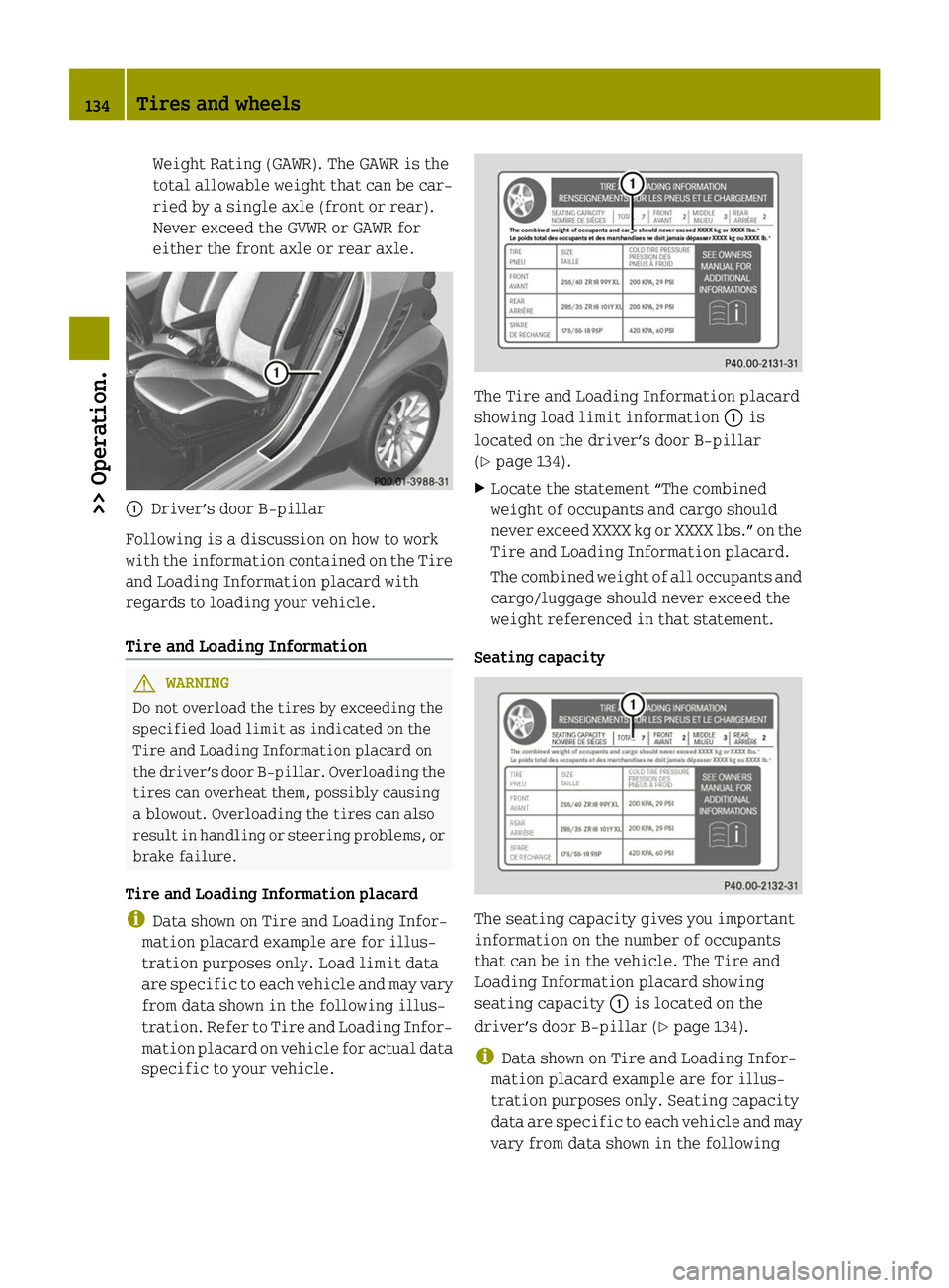
Weight Rating (GAWR). The GAWR is the
total allowable weight that can be car-
ried by a single axle (front or rear).
Never exceed the GVWR or GAWR for
either the front axle or rear axle.
0043
Driver’s door B‑pillar
Following is a discussion on how to work
with the information contained on the Tire
and Loading Information placard with
regards to loading your vehicle.
Tire and Loading Information G
WARNING
Do not overload the tires by exceeding the
specified load limit as indicated on the
Tire and Loading Information placard on
the driver’s door B‑pillar. Overloading the
tires can overheat them, possibly causing
a blowout. Overloading the tires can also
result in handling or steering problems, or
brake failure.
Tire and Loading Information placard
i Data shown on Tire and Loading Infor-
mation placard example are for illus-
tration purposes only. Load limit data
are specific to each vehicle and may vary
from data shown in the following illus-
tration. Refer to Tire and Loading Infor-
mation placard on vehicle for actual data
specific to your vehicle. The Tire and Loading Information placard
showing load limit information 0043is
located on the driver’s door B‑pillar
(Y page 134).
X Locate the statement “The combined
weight of occupants and cargo should
never exceed XXXX kg or XXXX lbs.” on the
Tire and Loading Information placard.
The combined weight of all occupants and
cargo/luggage should never exceed the
weight referenced in that statement.
Seating capacity The seating capacity gives you important
information on the number of occupants
that can be in the vehicle. The Tire and
Loading Information placard showing
seating capacity 0043is located on the
driver’s door B‑pillar (Y page 134).
i Data shown on Tire and Loading Infor-
mation placard example are for illus-
tration purposes only. Seating capacity
data are specific to each vehicle and may
vary from data shown in the following 134
Tires and wheels>> Operation.
Page 138 of 222

Examples for steps 1 to 3
Example 1 Example 2
Step 1 Combined weight limit of occu-
pants and cargo from Tire and Load-
ing Information placard
540 lbs 540 lbs
Step 2 Number of occupants (driver and
passenger)
2 1
Occupants weight
Occupant 1: 150 lbs
Occupant 2: 180 lbs Occupant 1: 150 lbs
Combined weight of all occupants
330 lbs 150 lbs
Step 3 Available cargo weight (total load
limit from Tire and Loading Infor-
mation placard minus combined
weight of all occupants)
540 lbs - 330 lbs =
210 lbs 540 lbs - 150 lbs =
390 lbs
Certification label
Even after careful determination of the
combined weight of all occupants and cargo
as to not exceed the permissible load
limit, you must make sure your vehicle
never exceeds the Gross Vehicle Weight
Rating (GVWR) and the Gross Axle Weight
Rating (GAWR) for either the front or rear
axle. You can obtain the GVWR and GAWR
from the certification label. The certifi-
cation label can be found on the driver’s
door B‑pillar, see “Technical data”
(Y
page 214).
Gross Vehicle Weight Rating (GVWR) means:
The total weight of the vehicle, all occu-
pants, and all cargo must never exceed the
GVWR.
Gross Axle Weight Rating (GAWR) means:
The total allowable weight that can be car-
ried by a single axle (front or rear).
To assure that your vehicle does not exceed
the maximum permissible weight limits
(GVWR and GAWR for front and rear axle),
have the loaded vehicle (including driver,
passenger, and all cargo) weighed on a
suitable commercial scale. Maximum tire load
G
WARNING
Do not overload the tires by exceeding the
specified load limit as indicated on the
Tire and Loading Information placard on
the driver’s door B‑pillar. Overloading the
tires can overheat them, possibly causing
a blowout. Overloading the tires can also
result in handling or steering problems, or
brake failure. i
For illustration purposes only. Actual
data on tires are specific to each vehicle
and may vary from data shown in above
illustration.
The maximum tire load 0043is the maximum
weight the tires are designed to support. 136
Tires and wheels>> Operation.