battery SMART FORTWO COUPE ELECTRIC DRIVE 2014 Owner's Manual
[x] Cancel search | Manufacturer: SMART, Model Year: 2014, Model line: FORTWO COUPE ELECTRIC DRIVE, Model: SMART FORTWO COUPE ELECTRIC DRIVE 2014Pages: 222, PDF Size: 16.17 MB
Page 93 of 222
This is useful:
R
if you wish to cool the interior of the
vehicle before driving
R if you wish to charge the vehicle at a
charging station/wallbox at the most
inexpensive electricity rate
With the "Air conditioning before start"
function, the vehicle interior is cooled
prior to a desired departure time.
Prerequisites:
R The doors and tailgate are closed.
R The charging cable for the high‑voltage
battery is connected to a power source
and inserted into the vehicle's power
socket.
R The high‑voltage battery has a suffi-
cient charge.
The maximum duration of "Air condition-
ing before start" is 30 minutes.
Set the air distribution of your vehicle as
follows so that the "Air conditioning
before start" function has the greatest
effect:
R in summer, to the center and side vents
R in winter, onto the windshield and side
windows
Information on air distribution can be
found on (Y page 102).
The setting of the airflow regulator has no
influence on the "Air conditioning before
start" function.
i If the programmed time is too short, the
high‑voltage battery cannot be com-
pletely charged. After setting the depar-
ture time, the maximum charge level
which can be reached is then shown.
i If the high‑voltage battery is not suf-
ficiently charged and the "Air condi-
tioning before start" function is acti-
vated, the high‑voltage battery is
charged first. When a charge level of at
least 20 % has been reached, the "Air con-
ditioning before start" function is acti-
vated. This function then has priority over the charging of the high‑voltage
battery.
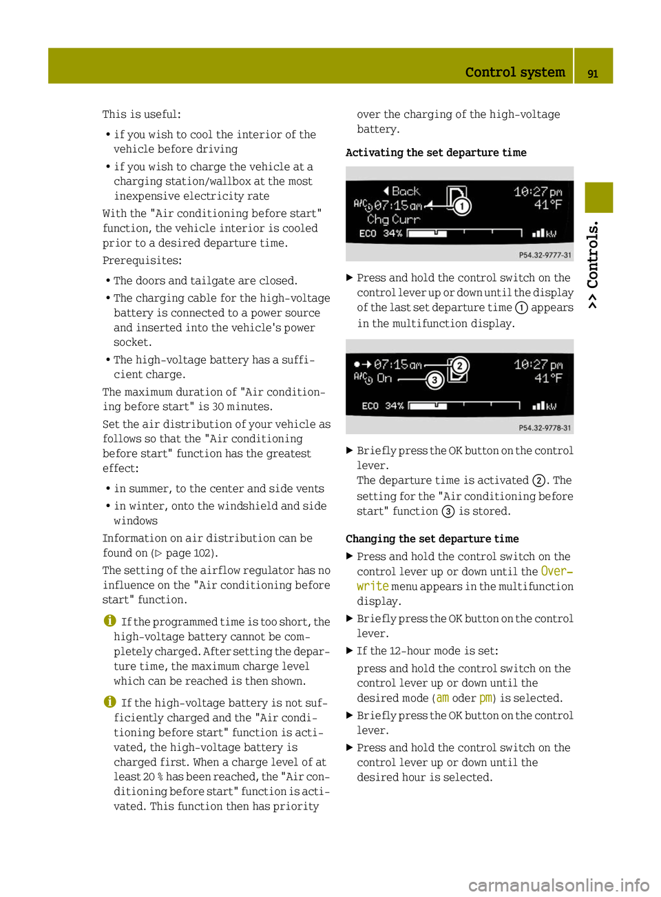
Activating the set departure time X
Press and hold the control switch on the
control lever up or down until the display
of the last set departure time 0043appears
in the multifunction display. X
Briefly press the OK button on the control
lever.
The departure time is activated 0044. The
setting for the "Air conditioning before
start" function 0087is stored.
Changing the set departure time
X Press and hold the control switch on the
control lever up or down until the Over‐ Over‐
write
write menu appears in the multifunction
display.
X Briefly press the OK button on the control
lever.
X If the 12-hour mode is set:
press and hold the control switch on the
control lever up or down until the
desired mode (am amoder pm
pm) is selected.
X Briefly press the OK button on the control
lever.
X Press and hold the control switch on the
control lever up or down until the
desired hour is selected. Control system
91>> Controls. Z
Page 94 of 222

X
Briefly press the OK button on the control
lever.
X Press and hold the control switch on the
control lever up or down until the "Air
conditioning before start" function is
activated or deactivated.
X Briefly press the OK button on the control
lever.
X Press and hold the control switch on the
control lever up or down until the "Air
conditioning before start" function is
activated or deactivated.
X Briefly press the OK button on the control
lever.
The new departure time is stored and
activated.
The "Air conditioning before start"
function is activated or deactivated.
Starting the charging process of the
high‑voltage battery immediately This function allows you to start the charg-
ing process immediately. The charging
process begins as soon as the charging
cable is connected.
i The charging process also begins when
you insert the charging cable into the
vehicle's power socket. However, this is
only the case if you have not made any
departure time settings.
Information on the charging process can
be found on (Y page 115).
X Press and hold the control switch on the
control lever up or down until the
Instant Charge
Instant Charge menu appears in the
multifunction display.
X Briefly press the OK button on the control
lever.
The charging process is started as soon
as the charging cable is connected.
i When you call up the Instant Charge
Instant Charge
menu, the "Air conditioning before
start" function is not available. Setting the maximum charge current G
WARNING
When connected to a power supply socket, a
high electrical load during the charging
process can lead to overheating of the
external power supply. There is a risk of
fire.
Check the maximum permissible charge
current on site before you begin the charg-
ing process. Contact an authorized electric
drive smart center should you require
assistance. If necessary, adjust the set-
tings of your vehicle.
You can limit the charge current of the
high‑voltage battery. This can protect the
power supply from overloading. You can set
the limit either on the control unit of the
charging cable or via the control system.
The preset standard value is "Max". This
corresponds to the maximum available
charge current of the power supply.
Check the maximum permissible charge
current for the respective power supply
socket before charging the high‑voltage
battery.
The following values are available for
selection: 8 A,12 A,Max. The last value set
remains stored until a change is made.
X Press and hold the control switch on the
control lever up or down until the
Charge Current Charge Current menu appears in the
multifunction display.
X Briefly press the OK button on the control
lever.
X Press and hold the control switch on the
control lever up or down until the
desired amperage is selected.
X Briefly press the OK button on the control
lever.
The selected amperage is set.
i If differing values are set on the charg-
ing cable and the control system, the
high‑voltage battery is charged using
the lowest value. 92
Control system>> Controls.
Page 95 of 222

i
If the vehicle needs more time to charge
the high‑voltage battery than usual,
check the settings of the maximum per-
missible charge current. Messages menu
The Messages Messages menu stores messages that
you can call up.
i When no messages have been stored, the
Messages
Messages menu is not displayed. X
Press the control switch on the control
lever (Y page 83) up or down until the
Messages Messages menu appears in the multi-
function display.
The number of stored messages is 0043dis-
played
X Press the OK button on the control lever
briefly.
The first stored message appears.
X To scroll through messages: Press the OK
button on the control lever briefly.
For more information on display messages,
see (Y page 161).
Maintenance service interval display The maintenance service interval display
will notify you when the next maintenance
service is due and what type of maintenance
service is required.
Example:
R 009A Main Service in XXX mi
Main Service in XXX mi
R 009A Main Service in XX Days Main Service in XX Days
X To confirm: Press the OK button on the
control lever briefly.
The mesage is stored. When the due date for the maintenance
service has been has been passed, the num-
ber of miles (kilometers) or days since are
preceeded by a minus sign.
!
Failure to have the maintenance
service performed at the designated
times/mileage, may result in vehicle
damage that is not covered by the smart
Limited Warranty. Settings menu
In the Settings Settings menu, you can select indi-
vidual settings for your vehicle.
The following functions are available:
R Setting the language
R Setting the temperature unit
R Setting the distance and speed unit
X Press the control switch on the control
lever (Y page 83) up or down until the
Settings Settings menu appears in the multi-
function display.
X Press the OK button on the control lever
briefly.
Setting the language The following languages are available:
R
German
R US English
R UK English
R French
R Italian
R Spanish X
Press the control switch on the control
lever (Y page 83) up or down until the Control system
93>> Controls. Z
Page 101 of 222

X
Press RES/+ button 0044briefly.
The cruise control resumes the previ-
ously set speed.
i The last set speed stored in memory is
deleted when the drive system is
switched off.
Changing the set speed You must have set a speed prior to increas-
ing or decreasing the current speed.
i Depressing the accelerator pedal does
not deactivate the cruise control. After
a brief acceleration (e.g. for passing),
the cruise control will resume the last
set speed.
Continuous adjustment
X Press and hold RES/+ button 0044to
increase the speed.
or
X Press and hold SET/ −0087 to decrease the
speed.
X Press and hold the respective button
until the desired speed is reached.
X Release the respective button.
The new speed is stored.
Adjustment in 1 mph (Canada 1 km/h) incre-
ments
X Press RES/+ button 0044briefly to increase
the speed.
or
X Press SET/ −0087 briefly to decrease the
speed.
The new speed is stored after releasing the
respective button. Air conditioning with climate control
Notes
G
WARNING
Follow the recommended settings for heat-
ing and cooling given on the following pages. Otherwise the windows could fog up,
impairing visibility and endangering you
and others.
The air conditioning improves the level of
comfort when driving at high outside tem-
peratures by cooling and dehumidifying
the air.
Nearly all dust particles, pollutants, are
filtered out by an integrated particle fil-
ter before outside air enters the passenger
compartment through the air distribution
system. It also operates when the air con-
ditioning is switched off and you have
switched on the blower.
The dehumidification of the air by the air
conditioner prevents the windows from
misting up when the outside air humidity
is high.
This effect can also be used to defrost the
windows. For this, make sure, in addition
to the air conditioner, that the heater is
on the maximum setting.
The air conditioner only works when:
R the ignition is switched on
R the blower is switched on
R the driver's door is closed
Maximum effectiveness is achieved if you
drive with the windows closed.
If the operating temperature of the
high‑voltage battery is too high, the
high‑voltage battery is cooled by the air
conditioner. When the air conditioner
switches on, the cooling output in the vehi-
cle's interior is reduced as a result. The
temperature in the vehicle's interior may
rise briefly.
If the air conditioner is not switched on,
the compressor of the air conditioner and
the vehicle's cooling fan are switched on
automatically. This cools the high‑voltage
battery but not the vehicle's interior. When
the high‑voltage battery reaches the nom-
inal temperature again, the air condi-
tioner switches off automatically. Air conditioning with climate control
99>> Controls. Z
Page 105 of 222

X
Increasing or decreasing: Push air vol-
ume control 0043up or down. Defrosting
G
WARNING
Never drive with iced up or fogged win-
dows. Visibility will be significantly
impaired. Impaired visibility could
endanger yourself and others. This may
prevent you from observing the traffic con-
ditions, thereby causing an accident.
The best defrosting of windows is achieved
if the ice is completely removed from the
windows manually with an ice scraper
before driving off.
Also use the "Air conditioning before
start" function (Y page 90).
Control panel (Y page 101).
X Switching on: Push air volume
control 0043to level 3.
X Turn air distribution control 0084to posi-
tion 0085.
X Push temperature control 0083fully up. Rear window defroster
The rear window defroster serves to de-ice
the rear window quickly and clear the view
if the rear window is fogged.
The rear window defroster uses a large
amount of power. To keep battery drain to a
minimum, switch off the rear window
defroster as soon as the rear window is
clear. The rear window defroster is auto-
matically deactivated after approximately
10 minutes of operation. X
Make sure the key is in starter switch
position 1.
X Switching on: Press rear window
defroster switch 0043.
The indicator lamp in rear window
defroster switch 0043comes on.
X Switching off: Press rear window
defroster switch 0043once more.
The indicator lamp in rear window
defroster switch 0043goes out. Air recirculation mode
Switch to air recirculation mode to prevent
unpleasant odors from entering the vehicle
from the outside (e.g. before driving
through a tunnel). This setting cuts off the
intake of outside air and recirculates the
air in the passenger compartment. G
WARNING
When the air recirculation mode is
switched on, windows can fog on the inside
immediately. Fogged windows impair vis-
ibility, endangering you and others. If the
windows begin to fog on the inside, switch-
ing off the air recirculation mode imme-
diately should clear interior window fog-
ging. If interior window fogging persists,
make sure the air conditioning is switched
on, turn air distribution control 0084to
position 0085and increase the air volume
using air volume control 0043.
Control panel (Y page 101). Air conditioning with climate control
103>> Controls. Z
Page 112 of 222

Auxiliary power outlet
The auxiliary power outlet supplies power
to the following electrical accessories
when the key is turned to starter switch
position 1:
R the electric air pump, available in con-
junction with the tire repair kit*
R other consumers which operate up to a
maximum of 60 W
! The auxiliary power outlet can accom-
modate 12V DC electrical accessories
designed for use with the standard “cig-
arette lighter” plug type.
Keep in mind, however, that connecting
accessories to the auxiliary power outlet
(for example extensive connecting and
disconnecting, or using plugs that do not
fit properly) can damage the auxiliary
power outlet.
The auxiliary power outlet is located in the
lower center console. Auxiliary power outlet
X
Turn the key to starter switch position 1.
! Please observe the safety instructions
given in the respective operating
instructions.
Please note that
R if using the auxiliary power outlet the
maximum current drawn may not exceed
5 A or 60 W
R the electric air pump* can be connected
to the auxiliary power outlet for the time it takes to inflate the tire without any
problem
R the vehicle battery will discharge when
current is drawn. 110
Useful features>> Controls.
* optional
Page 113 of 222

>> Operation.High-voltage battery
........................112
Front compartment ........................... 123
Tires and wheels .............................. 127
Winter driving ................................ 146
Driving instructions ........................147
Driving abroad ................................ 153
Vehicle care ................................... 153
Page 114 of 222

High-voltage battery
Introduction
The components of the drive system are
indicated by yellow warning labels to make
you aware of high voltage.
High-voltage cables are orange-colored. G
WARNING
The drive system is subject to high vol-
tages.
You may be seriously or even fatally injured
if you:
R tamper with components or high-voltage
cables in the drive system
R touch components or high-voltage cables
in the drive system on a vehicle which has
been involved in an accident
R touch damaged drive system components
Do not remove any drive system component
covers which are marked with a warning
sticker. Do not tamper with components or
orange high-voltage drive system cables. G
WARNING
The high‑voltage battery of the drive sys-
tem is located under the vehicle’s under-
body. When the pressure inside the
high‑voltage battery exceeds a certain
value, for example in case of a vehicle fire,
inflammable gas will escape via a duct. The
inflammable gas escapes to an area under
the vehicle. This prevents the high‑voltage
battery from exploding.
Stay away from this area of the vehicle. The drive system is powered by a high-
voltage battery. The high-voltage battery
stores and releases the energy required for
operation of the electric motor.
The electric motor uses the energy that is
stored in the high-voltage battery when
driving off and when accelerating.
When rolling, kinetic energy is converted
into electrical energy by energy recovery
and stored in the high-voltage battery.
The range of the vehicle is reduced when
consumers are switched on, e.g. climate
control.
The high-voltage battery can be charged in
a voltage range from 100 V to 240 V.
The high-voltage battery can be charged
R through energy recovery while the vehi-
cle is rolling or when braking
R Level 1 charging - 110 V / 120 V -
A travel cord will be supplied with the
vehicle. This charging cable can be
plugged into commonly available
110 V / 120 V, 15 A power sources. This
charging method will take longer to
charge your vehicle than a dedicated
level 2 charging source. Therefore it is
not recommended as the primary method
of charging.
R Level 2 charging - 220 V / 240 V -
For the fastest possible charging time, a
dedicated 220 V / 240 V, 20 A circuit is
required. Local electrical code can vary
from town to town. Therefore, it is highly
recommended that this service is pro-
fessionally installed. This service
should be installed in a dry area with
easy access to the passenger side of the
vehicle. You will need to obtain a vehicle
charge connector that can be wired
directly to or plugged into the dedicated
220 V / 240 V service. Charge connectors
will be available for purchase through
your authorized electric drive smart
center.
R Level 2 charging - Charging station 112
High-voltage battery>> Operation.
Page 115 of 222

Use only charging cables which have been
approved and recommended for the vehicle.
Do not use:
R extension chords
R cable reels
R multiple sockets
R travel adapters
i When possible, only charge the high-
voltage battery when the charge level is
below 80 %.
It is recommended to charge the high-
voltage battery prior to reaching less
than 20% state of charge.
Discharged high-voltage battery When the high-voltage battery is com-
pletely discharged, the drive system is
switched off. This protects the battery
from exhaustive discharge.
i By switching the ignition off and on
again, the drive system can be briefly
reactivated once. This allows you to park
the vehicle safely.
Do not allow your vehicle to remain sta-
tionary for more than 14 days with a dis-
charged, or nearly discharged, high-volt-
age battery. You can check the charge level
with the charge level gauge (Y page 81).
High or low outside temperatures The efficiency of the high-voltage battery
is temperature-dependent and decreases
at high or low temperatures. Additionally,
the electrolytes used can gel at very low
temperatures.
You can check the maximum capacity avail-
able using the indicator in the multifunc-
tion display (Y page 87). Energy consumption and range The available energy of the high-voltage
battery is reduced by:
R
low outside temperatures
R switching on electrical consumers
At low temperatures and after being parked
for an extended period without charging,
the physical properties of the high-volt-
age battery:
R can cause a significant reduction in the
performance of the battery
R can lead to longer charging times
In extreme cases, you will not be able to
start the vehicle. For this reason, always
connect the charging cable or make sure the
battery is completely charged when park-
ing the vehicle in low outside tempera-
tures or for an extended period of time.
Due to its physical properties, the capa-
city of a high-voltage battery decreases
over its lifespan.
Thus, the following are reduced:
R the maximum attainable range of the
vehicle
R the maximum performance output (accel-
eration) of the vehicle
You can actively contribute to the reduc-
tion of the vehicle's energy consumption
by:
R driving conservatively
R maintaining the vehicle regularly
R decreasing the use of electrical consum-
ers
Notes on battery care Avoid storing and transporting the vehicle
at high temperatures for extended periods
of time (e. g. container transport).
When out of use for longer periods of time,
connect the vehicle to a voltage supply.
If the vehicle is not connected to a voltage
supply, it must remain within a tempera- High-voltage battery
113>> Operation. Z
Page 116 of 222
 to 104 ‡
(40 ¥) .
When the vehicle is exposed to tempera-
tures below 00F813‡(00F825 ¥) for longer than
seven days, irreversible damage by frost
can occur.
Te")
ture range from
00F84‡(00F820 ¥) to 104 ‡
(40 ¥) .
When the vehicle is exposed to tempera-
tures below 00F813‡(00F825 ¥) for longer than
seven days, irreversible damage by frost
can occur.
Terms of use Observe the following notes:
R
exclusions of the high-voltage battery
terms of use in the battery rental con-
tract
R exclusions and limitations in the war-
ranty and guarantee documents, as well as
in the Service Booklet
R maintenance notes for the high-voltage
battery in the Service Booklet
Overvoltage protection !
Overvoltage in the on-board powersup-
ply system can damage the vehicle.
The vehicle is therefore equipped with a
protective device against overvoltage in
the power supply system. This protective
device can be activated in severe thun-
derstorms, for example, and lead to
security systems being triggered. This
function is used to protect the vehicle.
Once the security system has been reac-
tivated, the charging process continues
automatically.
Reactivate the security system after it has
been triggered. Otherwise the charging
process will not continue. The high-volt-
age battery is not being charged, which may
result in the vehicle not being ready to
start.
If you have secured other devices using the
same security system, they will also be
deactivated after this is triggered. Make
sure that these devices do function after
reactivating the security system. Charging cable and ‑connecter warming Observe the safety notes on (Y
page 112).
Charging cable and ‑connecter can become
warmed during charging process when con-
nected to a power source.
This warming is caused by
R high charge currents
R charging time
R transfer resistances at the plug contacts
R resistances of the charging cable
If the infrastructure of the power supply
system and charging cable are in good
order, the charging cable and ‑connecter
will only warm up within admissible
threshold.
Damaged charging cable plug or its con-
tacts may lead to warming above admissi-
ble threshold. In case of this, have the
cable, respectively power socket,
exchanged or disposed by a qualified elec-
trician. Charging at an AC power socket or a
private wallbox
Charging at an AC power socket G
WARNING
If you apply improperly installed power
sockets or adapters, extension cables or
similar to connect the charging cable to
power sockets, this may cause fire or lead
to electric shock. Risk of life!
In order to avoid the risk, please observe
the following:
R Connect the charging cable only to power
sockets which are
-properly installed
- approved by a qualified electrician
R For safety reasons only use charging
cables which have been supplied and
approved for the vehicle.
R Do not use a damaged charging cable. 114
High-voltage battery>> Operation.