display SMART FORTWO COUPE ELECTRIC DRIVE 2015 Owner's Guide
[x] Cancel search | Manufacturer: SMART, Model Year: 2015, Model line: FORTWO COUPE ELECTRIC DRIVE, Model: SMART FORTWO COUPE ELECTRIC DRIVE 2015Pages: 222, PDF Size: 5.02 MB
Page 165 of 222
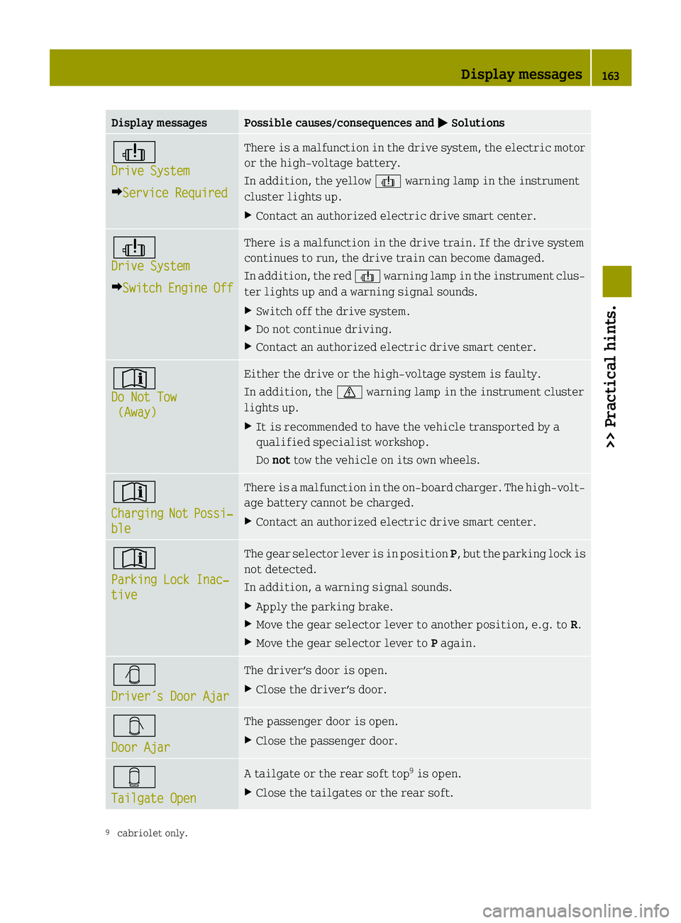
Display messages Possible causes/consequences and
M
MSolutions þ
Drive System Drive System
Y Service Required Service Required There is a malfunction in the drive system, the electric motor
or the high‑voltage battery.
In addition, the yellow þwarning lamp in the instrument
cluster lights up.
X Contact an authorized electric drive smart center. þ
Drive System Drive System
Y Switch
Switch Engine
EngineOff
Off There is a malfunction in the drive train. If the drive system
continues to run, the drive train can become damaged.
In addition, the red
þwarning lamp in the instrument clus-
ter lights up and a warning signal sounds.
X Switch off the drive system.
X Do not continue driving.
X Contact an authorized electric drive smart center. *
Do Not Tow Do Not Tow
(Away)
(Away) Either the drive or the high‑voltage system is faulty.
In addition, the
Nwarning lamp in the instrument cluster
lights up.
X It is recommended to have the vehicle transported by a
qualified specialist workshop.
Do not tow the vehicle on its own wheels. *
Charging Charging
Not
NotPossi‐
Possi‐
ble
ble There is a malfunction in the on-board charger. The high‑volt-
age battery cannot be charged.
X Contact an authorized electric drive smart center. *
Parking Lock Inac‐ Parking Lock Inac‐
tive tive The gear selector lever is in position
P, but the parking lock is
not detected.
In addition, a warning signal sounds.
X Apply the parking brake.
X Move the gear selector lever to another position, e.g. to R.
X Move the gear selector lever to Pagain. Ö
Driver´s Door Ajar Driver´s Door Ajar The driver’s door is open.
X Close the driver’s door. Ø
Door Ajar Door Ajar The passenger door is open.
X
Close the passenger door. Õ
Tailgate Open Tailgate Open A tailgate or the rear soft top
9
is open.
X Close the tailgates or the rear soft. 9
cabriolet only. Display messages
163>> Practical hints. Z
Page 166 of 222
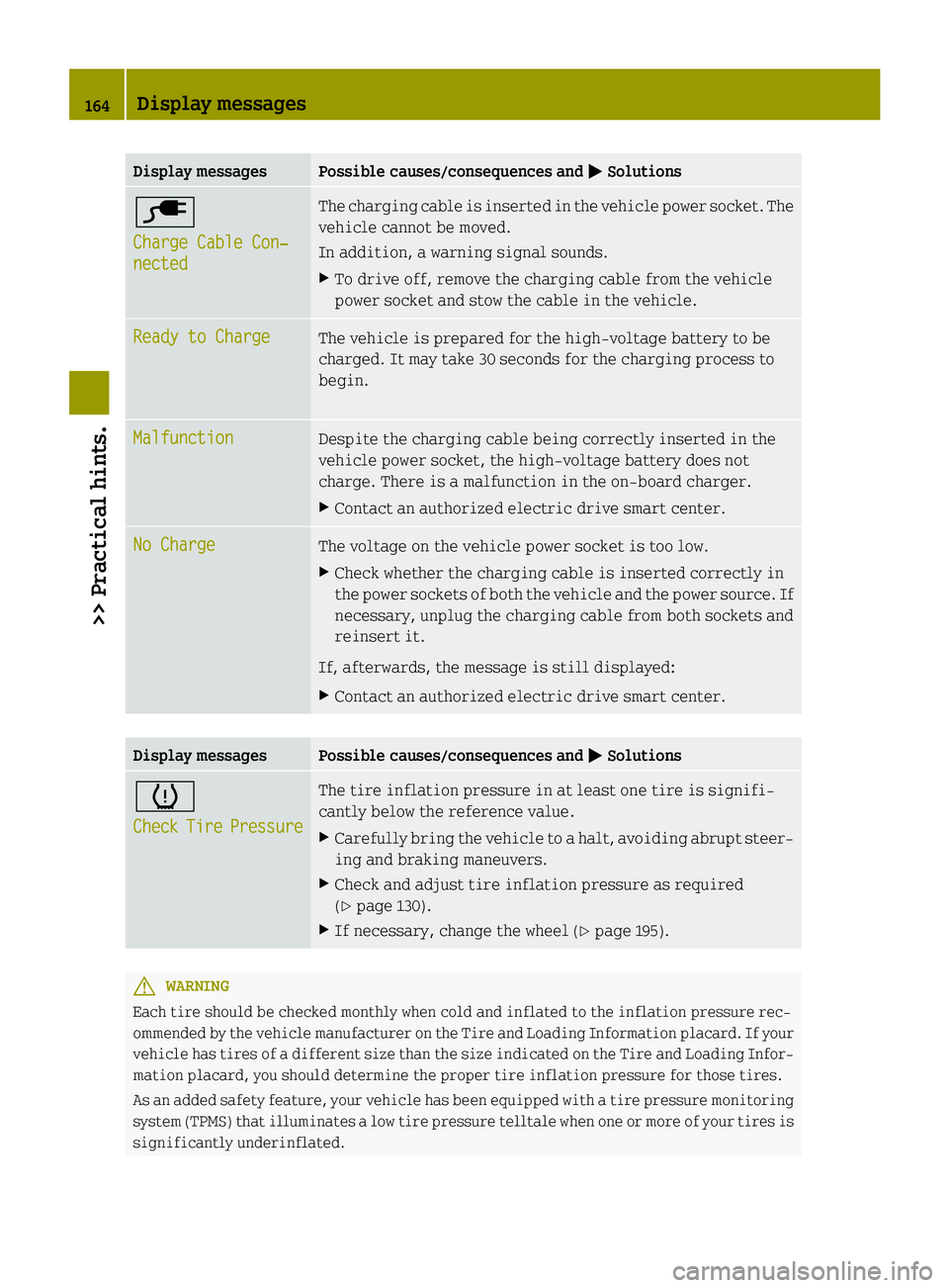
Display messages Possible causes/consequences and
M
MSolutions è
Charge Cable Con‐ Charge Cable Con‐
nected nected The charging cable is inserted in the vehicle power socket. The
vehicle cannot be moved.
In addition, a warning signal sounds.
X To drive off, remove the charging cable from the vehicle
power socket and stow the cable in the vehicle. Ready to Charge Ready to Charge
The vehicle is prepared for the high‑voltage battery to be
charged. It may take 30 seconds for the charging process to
begin.
Malfunction Malfunction
Despite the charging cable being correctly inserted in the
vehicle power socket, the high‑voltage battery does not
charge. There is a malfunction in the on-board charger.
X Contact an authorized electric drive smart center. No Charge No Charge
The voltage on the vehicle power socket is too low.
X Check whether the charging cable is inserted correctly in
the power sockets of both the vehicle and the power source. If necessary, unplug the charging cable from both sockets and
reinsert it.
If, afterwards, the message is still displayed:
X Contact an authorized electric drive smart center. Display messages Possible causes/consequences and
M MSolutions h
Check Check
Tire
TirePressure
Pressure The tire inflation pressure in at least one tire is signifi-
cantly below the reference value.
X Carefully bring the vehicle to a halt, avoiding abrupt steer-
ing and braking maneuvers.
X Check and adjust tire inflation pressure as required
(Y page 130).
X If necessary, change the wheel (Y page 195).G
WARNING
Each tire should be checked monthly when cold and inflated to the inflation pressure rec-
ommended by the vehicle manufacturer on the Tire and Loading Information placard. If your vehicle has tires of a different size than the size indicated on the Tire and Loading Infor- mation placard, you should determine the proper tire inflation pressure for those tires.
As an added safety feature, your vehicle has been equipped with a tire pressure monitoring
system (TPMS) that illuminates a low tire pressure telltale when one or more of your tires is
significantly underinflated. 164
Display messages>> Practical hints.
Page 167 of 222
Accordingly, when the low tire pressure telltale illuminates, you should stop and check your
tires as soon as possible, and inflate them to the proper pressure. Driving on a significantly underinflated tire causes the tire to overheat and can lead to tire failure.
Underinflation also reduces fuel efficiency and tire tread life, and may affect the vehicle’s
handling and stopping ability. Please note that the TPMS is not a substitute for proper tire maintenance, and it is the driver’s responsibility to maintain correct tire pressure, even
if underinflation has not reached the level to trigger illumination of the TPMS low tire
pressure telltale.
Your vehicle has also been equipped with a TPMS malfunction indicator to indicate when the
system is not operating properly. The TPMS malfunction indicator is combined with the low tire pressure telltale. When the system detects a malfunction, the telltale will flash for
approximately 1 minute and then remain continuously illuminated.
This sequence will continue upon subsequent vehicle start-ups as long as the malfunction
exists. When the malfunction indicator is illuminated, the system may not be able to detect or signal low tire pressure as intended.
TPMS malfunctions may occur for a variety of reasons, including the installation of incom-
patible replacement or alternate tires or wheels on the vehicle that prevent the TPMS from functioning properly. Always check the TPMS malfunction telltale after replacing one or
more tires or wheels on your vehicle to ensure that the replacement or alternate tires and
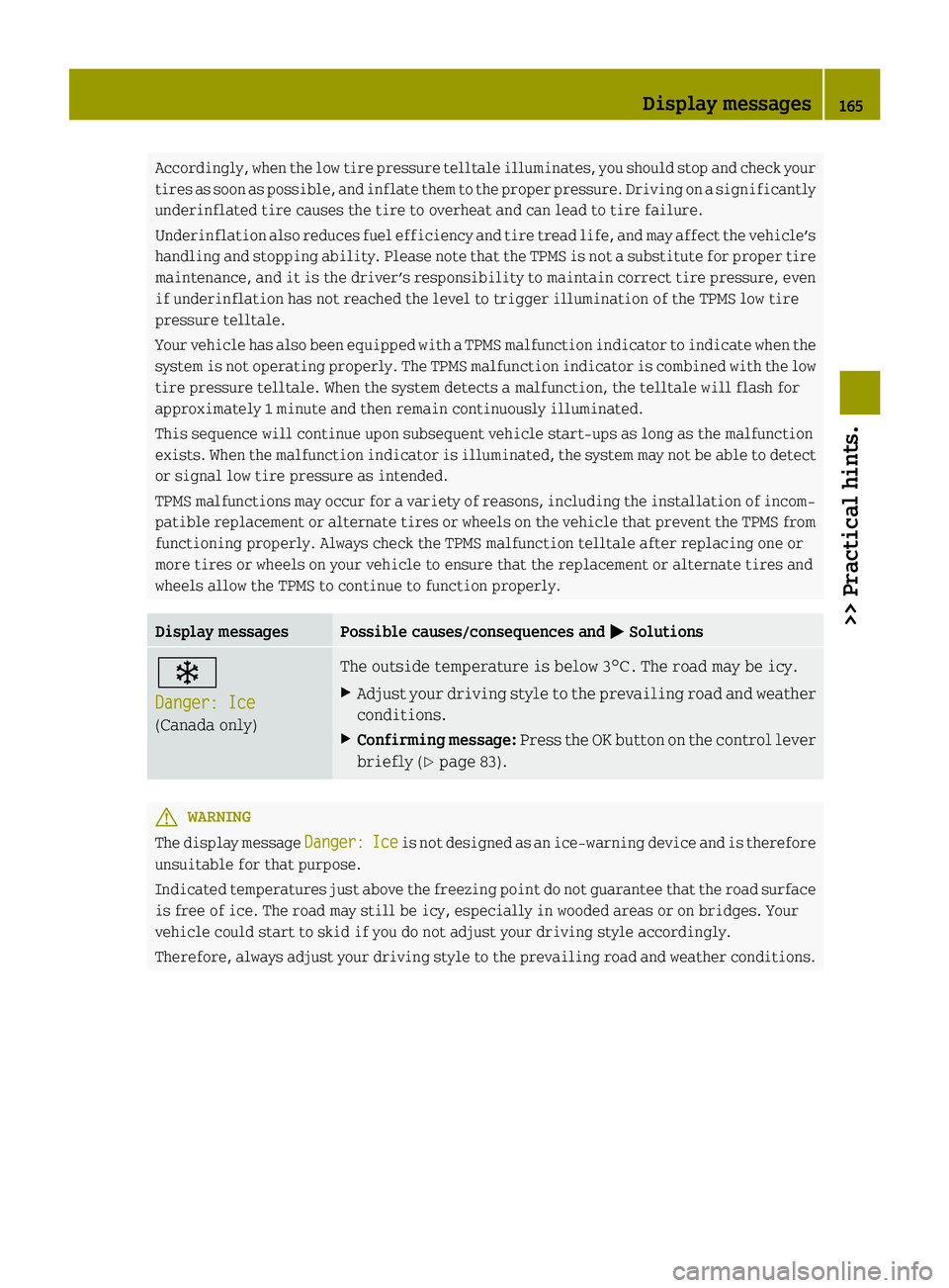
wheels allow the TPMS to continue to function properly. Display messages Possible causes/consequences and
M MSolutions Ò
Danger: Ice Danger: Ice
(Canada only) The outside temperature is below 3
¥. The road may be icy.
X Adjust your driving style to the prevailing road and weather
conditions.
X Confirming message: Press the OK button on the control lever
briefly (Y page 83). G
WARNING
The display message Danger: Danger:Ice
Iceis not designed as an ice-warning device and is therefore
unsuitable for that purpose.
Indicated temperatures just above the freezing point do not guarantee that the road surface
is free of ice. The road may still be icy, especially in wooded areas or on bridges. Your
vehicle could start to skid if you do not adjust your driving style accordingly.
Therefore, always adjust your driving style to the prevailing road and weather conditions. Display messages
165>> Practical hints. Z
Page 192 of 222
X
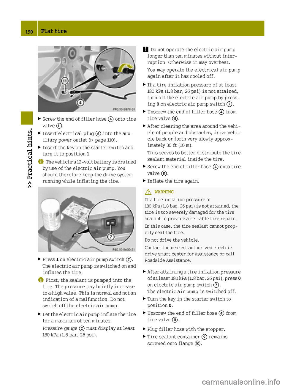
Screw the end of filler hose ?onto tire
valve G.
X Insert electrical plug Binto the aux-
iliary power outlet (Y page 110).
X Insert the key in the starter switch and
turn it to position 1.
i The vehicle’s 12‑volt battery is drained
by use of the electric air pump. You
should therefore keep the drive system
running while inflating the tire. X
Press Ion electric air pump switch C.
The electric air pump is switched on and inflates the tire.
i First, the sealant is pumped into the
tire. The pressure may briefly increase
to a high value. This is normal and not an
indication of a malfunction. Do not
switch off the electric air pump.
X Let the electric air pump inflate the tire
for a maximum of ten minutes.
Pressure gauge ;must display at least
180 kPa (1.8 bar, 26 psi). !
Do not operate the electric air pump
longer than ten minutes without inter-
ruption. Otherwise it may overheat.
You may operate the electrical air pump
again after it has cooled off.
X If a tire inflation pressure of at least
180 kPa (1.8 bar, 26 psi) is not attained,
turn off the electric air pump by press-
ing 0on electric air pump switch C.
X Unscrew the end of filler hose ?from
tire valve G.
X After clearing the area around the vehi-
cle of people and obstacles, drive vehi-
cle back or forth very slowly approx-
imately 30 ft (10 m).
This serves to better distribute the tire sealant material inside the tire.
X Screw the end of filler hose ?onto tire
valve G.
X Inflate the tire again. G
WARNING
If a tire inflation pressure of
180 kPa (1.8 bar, 26 psi) is not attained, the tire is too severely damaged for the tire
sealant to provide a reliable tire repair.
In this case, the tire sealant cannot prop-
erly seal the tire.
Do not drive the vehicle.
Contact the nearest authorized electric
drive smart center for assistance or call
Roadside Assistance.
X After attaining a tire inflation pressure
of at least 180 kPa (1.8 bar, 26 psi), press 0
on electric air pump switch C.
The electric air pump is switched off.
X Turn the key in the starter switch to
position 0.
X Unscrew the end of filler hose ?from
tire valve G.
X Plug filler hose with the stopper.
X Tire sealant container Eremains
screwed onto flange F.190
Flat tire>> Practical hints.
Page 194 of 222
X
Drive to the nearest authorized electric
drive smart center, to have the damaged
tire replaced.
X Contact an authorized electric drive
smart center as soon as possible to
obtain a new filler hose and a new tire
sealant container.
X Bring used tire sealant materials to an
authorized electric drive smart center
for proper disposal.
X Replace your tire sealant container
every 4 years. Replacement containers
are available at any authorized electric
drive smart center. G
WARNING
After changing a tire, contact an author-
ized electric drive smart center to make
sure the bolts holding the wheel to the car
are tight enough. Otherwise, the wheels
could come off. Each bolt should be tight-
ened to a torque of 81 lb‑ft (110 Nm). Sealing a tire (Version 2)
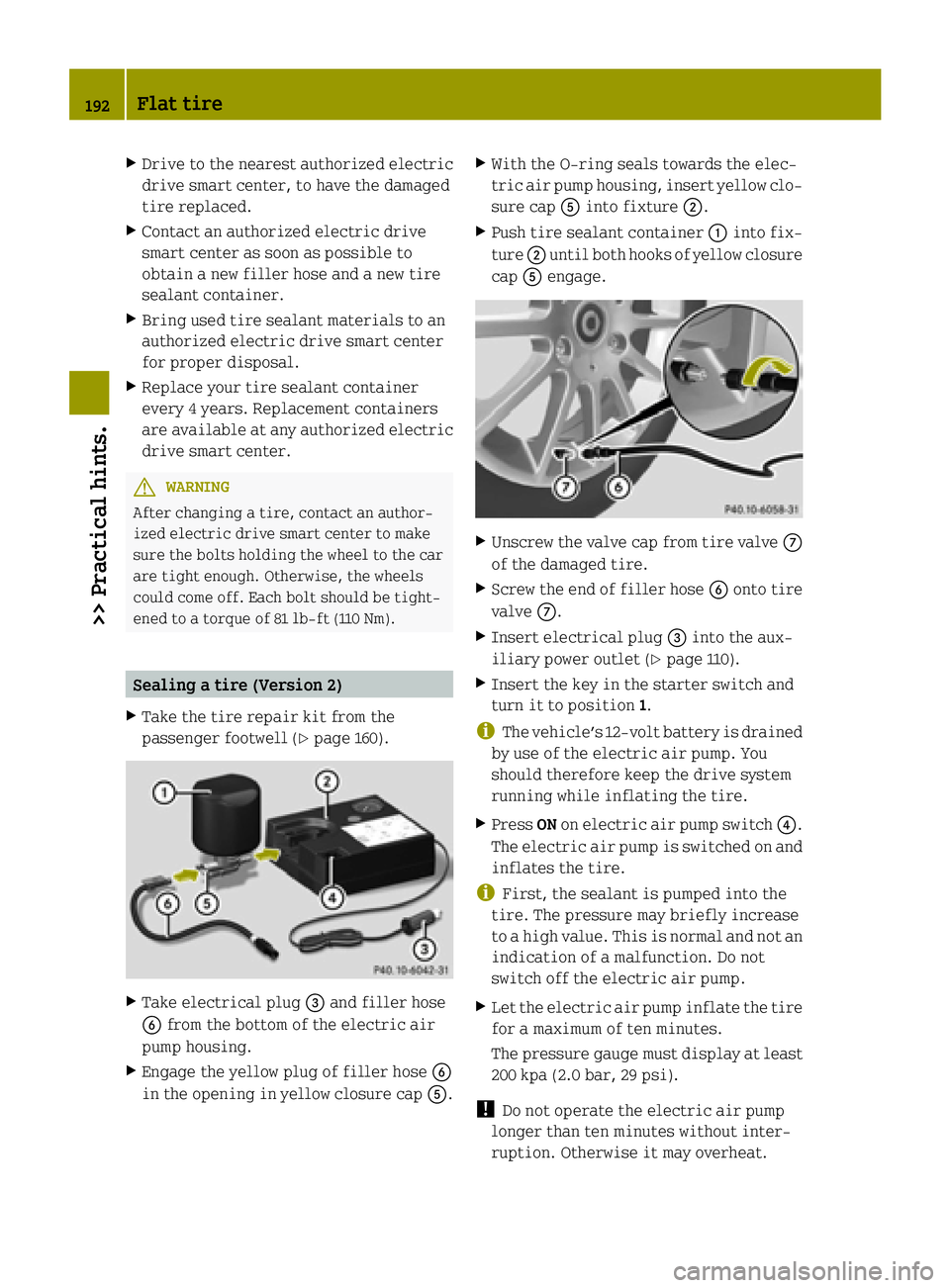
X Take the tire repair kit from the
passenger footwell (Y page 160).X
Take electrical plug =and filler hose
B from the bottom of the electric air
pump housing.
X Engage the yellow plug of filler hose B
in the opening in yellow closure cap A.X
With the O-ring seals towards the elec-
tric air pump housing, insert yellow clo-
sure cap Ainto fixture ;.
X Push tire sealant container :into fix-
ture ;until both hooks of yellow closure
cap Aengage. X
Unscrew the valve cap from tire valve C
of the damaged tire.
X Screw the end of filler hose Bonto tire
valve C.
X Insert electrical plug =into the aux-
iliary power outlet (Y page 110).
X Insert the key in the starter switch and
turn it to position 1.
i The vehicle’s 12‑volt battery is drained
by use of the electric air pump. You
should therefore keep the drive system
running while inflating the tire.
X Press ONon electric air pump switch ?.
The electric air pump is switched on and
inflates the tire.
i First, the sealant is pumped into the
tire. The pressure may briefly increase
to a high value. This is normal and not an
indication of a malfunction. Do not
switch off the electric air pump.
X Let the electric air pump inflate the tire
for a maximum of ten minutes.
The pressure gauge must display at least200 kpa (2.0 bar, 29 psi).
! Do not operate the electric air pump
longer than ten minutes without inter-
ruption. Otherwise it may overheat. 192
Flat tire>> Practical hints.
Page 205 of 222
X
Remove the jumper cables from negative terminals =and ?first.
X Remove the jumper cables from positive terminals :and ;.
You can now switch on the headlamps.
X Remount the positive terminal cover.
X Have the 12-volt battery checked at the nearest authorized electric drive smart center.
i Please keep in mind that it will take quite some time to charge the 12-volt battery.
When you switch off the drive system after driving a short distance, you may not be able to start it again.
Charge the 12-volt battery completely as soon as possible. Towing
About towing
This section offers information on towing
methods for breakdown situations and
emergency towing. Recommended towing method - Break-
down situation
! To prevent damage during transport, do
not tie down the vehicle by its chassis or suspension parts — use only wheel straps to position and hold down the vehicle.
Improper tie down on a flatbed carrier
truck or trailer can damage suspension
parts and body panels.
smart recommends that the vehicle be
transported with all wheels off the ground
using a flatbed carrier truck or appropri- ate wheel lift/dolly equipment.
Always have your vehicle transported:
R when the Nwarning lamp for the high-
voltage system lights up in the instru-
ment cluster
R when the Do not tow (away)
Do not tow (away) message
appears in the instrument cluster
R when the multifunction display is inop-
erative R
when one or several of the following
warning lamps light up:
- þ Drive diagnostics (red)
- # 12‑Volt battery
D Power steering
R if the brake pedal already starts to pul-
sate just after towing begins
R if you have to transport the vehicle over
long distances
X Switch off the tow‑away protection* and
interior motion sensor* (Y page 50). Emergency towing
When circumstances do not permit the rec-
ommended towing method, the vehicle may
be towed with all wheels on the ground
using a strap or tow bar connected to
another vehicle. Only tow the vehicle as far as necessary to have the vehicle moved to a
safe location where the recommended tow-
ing method can be employed. G
WARNING
If circumstances require towing the vehi-
cle with all wheels on the ground, always tow
with a tow bar if:
R the drive system will not run
R there is a malfunction in the brake sys-
tem
R there is a malfunction in the power sup-
ply or in the vehicle’s electrical system Towing
203>> Practical hints.
* optional Z