air condition SMART FORTWO COUPE ELECTRIC DRIVE 2015 Owners Manual
[x] Cancel search | Manufacturer: SMART, Model Year: 2015, Model line: FORTWO COUPE ELECTRIC DRIVE, Model: SMART FORTWO COUPE ELECTRIC DRIVE 2015Pages: 222, PDF Size: 5.02 MB
Page 6 of 222

1, 2, 3 ...
12-volt battery Charging ................................ 199
Indicator lamp ........................ .171
Notes ..................................... 197
Removing and installing ............ 199 A
ABS (Antilock Brake System) ............. 46
Indicator lamp .........................1 67
Accessory weight .......................... 143
Accidents
Air bags .................................. 33
Acoustic Vehicle Indication* ........... 48
Address change .............................. 15
Air bags ....................................... 33
Children .................................. 33
Front, driver and passenger ......... 36
Front, passenger ....................... 36
Head-thorax ............................. 37
Knee bag .................................. 36
Passenger front air bag off
indicator lamp ..................... 28, 41
Safety guidelines ...................... 35
SRS indicator lamp ...................1 69
Thorax-pelvis ........................... 37
Window curtain ......................... 37
Air conditioning with climate con-
trol
Air distribution ...................... 102
Air recirculation mode .............1 03
Air vents ................................ 101
Air volume .............................. 102
Control panel .......................... 101
Defrosting .............................. 103
Notes ...................................... 99
Rear window defroster ............... 103
Switching on/off ...................... 101
Temperature ............................ 101
Air pressure
see Tire inflation pressure
Air pressure (tires) ...................... 144
Air vents .................................... .101
Alarm system
see Anti-theft systems
Ambient lighting* .......................... 67 Anti-theft systems
.........................48
Anti-theft warning system ........... 49
Electronic immobilizer .............. 48
Interior motion sensor ............... 49
Tow-away alarm .........................49
Anticorrosion/antifreeze ............... 219
Antiglare, Interior rear view mir-
ror .............................................. 61
Antilock Brake System
see ABS
Aquaplaning
see Hydroplaning
Armrest ........................................ 59
Aspect ratio (tires) ....................... 144
Audio system .................................95
Basic ...................................... 96
Navigation/multimedia .............. 96
Automatic headlamp mode ................64
Automatic locking .......................... 53
AUX socket .................................... 96 B
Backrest see Seats
Backup lamp .................................1 81
Bar (air pressure unit) ...................144
Batteries ....................................1 97
Battery
Jump starting .......................... 200
Battery (key)
Replacing the transmitter bat-
tery ....................................... 178
Battery coolant ............................ 125
Bead (tire) .................................. 144
Brake fluid .................................. 127
Checking ................................ 127
Brake lamp ................................... 181
Brake pedal ................................... 78
Brakes ........................................ 148
Parking brake ........................... 77
Warning lamp ........................... 167
Bulbs
Front .................................... .180
Rear ...................................... 181
Replacing .............................. .179 4
Index
Page 16 of 222

R State")
R
Corrosion Warranty
R California, Connecticut, Maine, Massa-
chusetts, New York, Pennsylvania, Rhode
Island, and Vermont Emission Control
System Warranty
R smartmove Assistance (Canada only)
R State Warranty Enforcement Laws (Lemon
Laws, USA only) Important notice for California retail
buyers and lessees of smart automo-
biles
Under California law you may be entitled to
a replacement of your vehicle or a refund of
the purchase price or lease price, if
Mercedes-Benz USA LLC and/or its author-
ized repair or service facilities fail to
fix one or more substantial defects or mal- functions in the vehicle that are covered by
its express warranty after a reasonable
number of repair attempts. During the
period of 18 months from original delivery
of the vehicle or the accumulation of
18 000 miles (approximately 29 000 km) on the odometer of the vehicle, whichever
occurs first, a reasonable number of repair
attempts is presumed for a retail buyer or
lessee if one or more of the following
occurs:
(1) the same substantial defect or mal- function results in a condition that is
likely to cause death or serious bodilyinjury if the vehicle is driven, that
defect or malfunction has been subject
to repair two or more times, and you
have directly notified Mercedes-Benz
USA LLC in writing of the need for its
repair,
(2) the same substantial defect or mal- function of a less serious nature than
category (1) has been subject to repair four or more times and you have directly notified us in writing of the
need for its repair, or
(3) the vehicle is out of service by reason of repair of the same or different sub-
stantial defects or malfunctions for a
cumulative total of more than 30 cal-
endar days.
Written notification should not be sent to a dealer, it should be addressed to:
Mercedes-Benz USA LLC
One Mercedes Drive
Montvale, NJ 07645 Maintenance
The Scheduled Maintenance Guide (USA) and
Service Booklet (Canada) describes all the
necessary maintenance work which should
be performed at regular intervals. It is
important that you service your vehicle in accordance with the prescribed mainte-
nance schedule. Failure to do so may render your vehicle unsafe, it may affect the dura-
bility of the vehicle, and it may otherwise
void the limited, express warranty.
Always have the Scheduled Maintenance
Guide (USA) or Service Booklet (Canada)
with you when you take the vehicle to your
authorized electric drive smart center for
service. The service advisor will record
each service in the booklet for you. Operating range
If you plan a long distance trip, please be
aware that:
R You will need to have access to an AC
power socket or a private wallbox to 14
>> Introduction.
Page 21 of 222

that a safety defect exists in a group of
vehicles, it may order a recall and remedy
campaign. However, NHTSA cannot become
involved in individual problems between
you, your dealer, or Mercedes-Benz USA
LLC.
To contact NHTSA, you may call the Vehicle Safety Hotline toll-free at 1-888-327-4236
(TTY: 1-800-424-9153); go to
http://www.safercar.gov ; or write to:
Administrator, NHTSA Headquarters, 1200
New Jersey Avenue, SE, West Building,
Washington, DC 20590. You can also obtain
other information about motor vehicle
safety from http://www.safercar.gov. Vehicle data recording
Data recording
This vehicle is capable of recording diag-
nostic information relating to vehicle
operation, malfunctions, and user set-
tings. This may include information about
the performance or status of various sys-
tems, including but not limited to, engine, throttle, steering or brake systems, that isstored and can be read out with suitable
devices, particularly when the vehicle is
serviced. The data obtained is used to
properly diagnose and service your vehi-
cle or to further optimize and develop
vehicle functions. Event data recorders
This vehicle is equipped with an event data
recorder (EDR). The main purpose of an EDR is to record data that will assist in under- standing how a vehicle’s systems performed
in certain crash or near crash-like situa-
tions, such as during air bag deployment or when hitting a road obstacle. The EDR is
designed to record data related to vehicle
dynamics and safety systems for a short
period of time, typically 30 seconds or
less. The EDR in this vehicle is designed to
record such data as:
R how various systems in your vehicle are
operating
R whether or not the driver and passenger
seat belts are fastened
R how far (if at all) the driver is depress-
ing the accelerator and/or brake pedal
and
R how fast the vehicle is traveling
This data can help provide a better under-
standing of the circumstances in which
crashes and injuries occur. NOTE: EDR data
is recorded by your vehicle only if a non-
trivial crash situation occurs; no data is
recorded by the EDR under normal driving
conditions and no personal data (e.g.,
name, gender, age, and crash location) are
recorded. However, other parties, such as
law enforcement, can combine the EDR data with the type of personal identification
data routinely acquired during a crash
investigation.
To read data recorded by an EDR, special
equipment is required, and access to the
vehicle or the EDR is needed. In addition to
the vehicle manufacturer, other parties
that have the special equipment, such as
law enforcement, can read the information
by accessing the vehicle or the EDR.
EDR data may be used in civil and criminal
matters as a tool in accident reconstruc-
tion, accident claims, and vehicle safety.
Since the Crash Data Retrieval CDR tool
that is used to extract data from the EDR is commercially available, Mercedes-Benz
USA, LLC ("MBUSA") expressly disclaims
any and all liability arising from the
extraction of this information by unau-
thorized Mercedes-Benz personnel.
MBUSA will not share EDR data with others
without the consent of the vehicle owners
or, if the vehicle is leased, without the
consent of the lessee. Exceptions to this
representation include responses to sub-
poenas by law enforcement; by federal, >> Introduction.
19 Z
Page 29 of 222

Center console
Function Page
:
Charge level gauge 81
;
Power gauge 81
=
Air conditioning with
climate control 99
?
Radio 95
A
Drawer 107
B
Switching seat heating*
on/off
60
C
Restarting TPMS button 130
D
Switching tow-away pro-
tection*/interior motion
sensor* on/off
49
E
Central unlocking switch 53 Function Page
F
Hazard warning flasher
switch
68
G
Central locking switch 53
H
Switching front fog
lamps* on/off
67
I
Storage tray* 107
J
Gear selector lever 79
K
Starter switch 57
L
Parking brake lever 77
M
Coin holder 106
Retractable soft top
switch
2 72
2
cabriolet only. Center console
27>> At a glance.
* optional
Page 53 of 222

>> Controls.Opening and closing .......................... 52
Starter switch positions ....................
.57
Seats .............................................. 58
Mirrors ........................................... 61
Seat belts ........................................ 62
Lighting ........................................ .64
Windshield wipers ............................ 69
Soft top system (cabriolet only) ............ 70
Side windows .................................... 75
Driving and parking .......................... 76
Transmission ................................... 79
Instrument cluster ............................. 81
Control system .................................. 83
Audio system* .................................. 95
Driving systems ................................ 97
Air conditioning with climate control .. 99
Loading and storing ......................... 104
Useful features ................................ 109
Page 81 of 222

Make sure the drive system is active when-
ever the vehicle is rolling. Have the brake system repaired at an authorized electric
drive smart center, if there is a fault in the
brake system. If a brake circuit has failed (Y
page 167),
you must depress brake pedal :further
down to achieve the same effect and the
braking distance is increased.
i The brake servo will only function with
the ignition switched on. Switching off the drive system
G
WARNING
Do not turn off the drive system before the
vehicle has come to a complete stop. With
the drive system not running, there is no
power assistance for the brake and steering systems. In this case, it is important to
keep in mind that a considerably higher
degree of effort is necessary to brake and
steer the vehicle.
X Depress the brake pedal.
X Move the gear selector lever to park
position P.
The transmission position indicator
should be on P
P
! Always engage the parking brake in
addition to shifting to park position P.X
Release the brake pedal.
X Turn the key to starter switch position 0.
X Remove the key from the starter switch.
The electronic immobilizer is activa-
ted. Transmission
Shifting procedure
Gearshift pattern for transmission
j
Park position
k
Reverse gear
i
Neutral position
h
Drive position
Select a gear:
X
Switch on the ignition.
X Depress the brake pedal.
X Move the gear selector lever to the
desired position. Steering wheel paddle shifters* (for
recuperation)
G
WARNING
The operating condition of the high-volt-
age battery (e.g. not yet at normal operat-
ing temperature or fully charged) influen- ces the braking effect of the electric
motor. Transmission
79>> Controls.
* optional Z
Page 92 of 222

Odometer
Odometer
menu appears in the multi-
function display.
X To switch between submenus: Press the OK
button on the control lever briefly.
X To reset the trip odometer: Select the
trip odometer display.
X Press button Bon the instrument cluster
until the trip odometer is reset to 0
(Y page 23).
If the remaining cruise range of the charge level of the high-voltage battery has drop-
ped below 10 %, Low Battery
Low Battery is displayed
on position =. Start menu
The YSTARTSTART menu shows you the trip statis-
tics since start. :
Average speed since start
; Time elapsed since start
= Distance driven since start
? Average energy consumption
X Press the control switch on the control
lever (Y page 83) up or down until the
YSTART START menu appears in the multifunc-
tion display.
X To reset: Press button Bon the instru-
ment cluster until the YSTARTSTART menu is
reset to 0(Y page 23).
i The YSTARTSTART menu is reset to 0 automat-
ically
R when the ignition has been switched
off for more than 4 hours
R after driving more than 9999 miles or
kilometers Reset menu
The YRESETRESET menu menu shows you the trip
statistics since the last reset. :
Average speed since last reset
; Time elapsed since since last reset
= Distance driven since last reset
? Average energy consumption
X Press the control switch on the control
lever (Y page 83) up or down until the
YRESET RESET menu appears in the multifunc-
tion display.
X To reset: Press button Bon the instru-
ment cluster until the YRESETRESET menu is
reset to 0(Y page 23). Charge and depart menu
In the Charge and Depart Charge and Depart menu you can
change the following settings:
R set a departure time
R switch on/off the "Air conditioning
before start" function
R instant charge of the high‑voltage bat-
tery
R set the maximum charge current.
X Press the control switch on the control
lever up or down until Charge and Charge and
Depart
Depart appears in the multifunction
display.
X Press the OK button on the control lever
briefly.
Setting the departure time With this function, you can preset a depar-
ture time. 90
Control system>> Controls.
Page 93 of 222
This is useful:
R if you wish to cool the interior of the
vehicle before driving
R if you wish to charge the vehicle at a
charging station/wallbox at the most
inexpensive electricity rate
With the "Air conditioning before start"
function, the vehicle interior is cooled
prior to a desired departure time.
Prerequisites:
R The doors and tailgate are closed.
R The charging cable for the high‑voltage
battery is connected to a power source
and inserted into the vehicle's power
socket.
R The high‑voltage battery has a suffi-
cient charge.
The maximum duration of "Air condition-
ing before start" is 30 minutes.
Set the air distribution of your vehicle as
follows so that the "Air conditioning
before start" function has the greatest
effect:
R in summer, to the center and side vents
R in winter, onto the windshield and side
windows
Information on air distribution can be
found on (Y page 102).
The setting of the airflow regulator has no
influence on the "Air conditioning before
start" function.
i If the programmed time is too short, the
high‑voltage battery cannot be com-
pletely charged. After setting the depar- ture time, the maximum charge level
which can be reached is then shown.
i If the high‑voltage battery is not suf-
ficiently charged and the "Air condi-
tioning before start" function is acti-
vated, the high‑voltage battery is
charged first. When a charge level of at
least 20 %has been reached, the "Air con-
ditioning before start" function is acti-
vated. This function then has priority over the charging of the high‑voltage
battery.
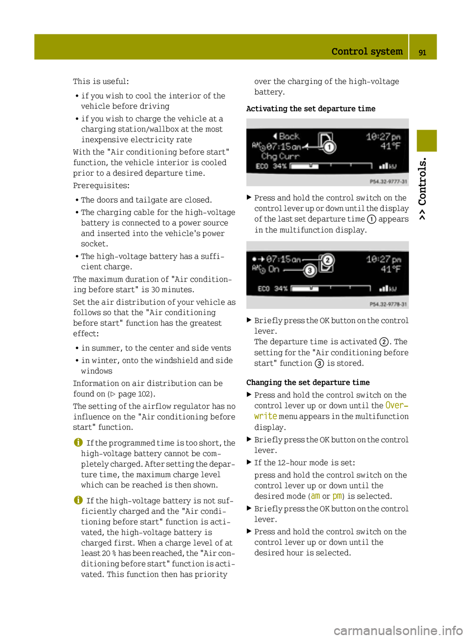
Activating the set departure time X
Press and hold the control switch on the
control lever up or down until the display
of the last set departure time :appears
in the multifunction display. X
Briefly press the OK button on the control
lever.
The departure time is activated ;. The
setting for the "Air conditioning before
start" function =is stored.
Changing the set departure time X Press and hold the control switch on the
control lever up or down until the Over‐
Over‐
write write menu appears in the multifunction
display.
X Briefly press the OK button on the control
lever.
X If the 12-hour mode is set:
press and hold the control switch on the
control lever up or down until the
desired mode (am amorpm pm) is selected.
X Briefly press the OK button on the control
lever.
X Press and hold the control switch on the
control lever up or down until the
desired hour is selected. Control system
91>> Controls. Z
Page 94 of 222

X
Briefly press the OK button on the control
lever.
X Press and hold the control switch on the
control lever up or down until the
desired minute is selected.
X Briefly press the OK button on the control
lever.
X Press and hold the control switch on the
control lever up or down until the "Air
conditioning before start" function is
activated or deactivated.
X Briefly press the OK button on the control
lever.
The new departure time is stored and
activated.
The "Air conditioning before start"
function is activated or deactivated.
Starting the charging process of the
high‑voltage battery immediately This function allows you to start the charg-
ing process immediately. The charging
process begins as soon as the charging
cable is connected.
i The charging process also begins when
you insert the charging cable into the
vehicle's power socket. However, this is
only the case if you have not made any
departure time settings.
Information on the charging process can
be found on (Y page 115).
X Press and hold the control switch on the
control lever up or down until the
Instant Charge
Instant Charge menu appears in the
multifunction display.
X Briefly press the OK button on the control
lever.
The charging process is started as soon
as the charging cable is connected.
i When you call up the Instant Charge Instant Charge
menu, the "Air conditioning before
start" function is not available. Setting the maximum charge current G
WARNING
When connected to a power supply socket, a
high electrical load during the charging
process can lead to overheating of the
external power supply. There is a risk of
fire.
Check the maximum permissible charge
current on site before you begin the charg-
ing process. Contact an authorized electric drive smart center should you require
assistance. If necessary, adjust the set-
tings of your vehicle.
You can limit the charge current of the
high‑voltage battery. This can protect the
power supply from overloading. You can set
the limit either on the control unit of the
charging cable or via the control system.
The preset standard value is "Max". This
corresponds to the maximum available
charge current of the power supply.
Check the maximum permissible charge
current for the respective power supply
socket before charging the high‑voltage
battery.
The following values are available for
selection: 8 A,12 A,Max. The last value set
remains stored until a change is made.
X Press and hold the control switch on the
control lever up or down until the
Charge Current Charge Current menu appears in the
multifunction display.
X Briefly press the OK button on the control
lever.
X Press and hold the control switch on the
control lever up or down until the
desired amperage is selected.
X Briefly press the OK button on the control
lever.
The selected amperage is set.
i If differing values are set on the charg-
ing cable and the control system, the
high‑voltage battery is charged using
the lowest value. 92
Control system>> Controls.
Page 101 of 222

X
Press RES/+ button ;briefly.
The cruise control resumes the previ-
ously set speed.
i The last set speed stored in memory is
deleted when the drive system is
switched off.
Changing the set speed You must have set a speed prior to increas-
ing or decreasing the current speed.
i Depressing the accelerator pedal does
not deactivate the cruise control. After a brief acceleration (e.g. for passing), the
cruise control will resume the last set
speed.
Continuous adjustment
X Press and hold RES/+ button ;to
increase the speed.
or
X Press and hold SET/ −= to decrease the
speed.
X Press and hold the respective button
until the desired speed is reached.
X Release the respective button.
The new speed is stored.
Adjustment in 1 mph (Canada 1 km/h) incre- ments
X Press RES/+ button ;briefly to increase
the speed.
or X Press SET/ −= briefly to decrease the
speed.
The new speed is stored after releasing the respective button. Air conditioning with climate control
Notes
G
WARNING
Follow the recommended settings for heat-
ing and cooling given on the following pages. Otherwise the windows could fog up,
impairing visibility and endangering you
and others.
The air conditioning improves the level of
comfort when driving at high outside tem-
peratures by cooling and dehumidifying
the air.
Nearly all dust particles, pollutants, are
filtered out by an integrated particle fil-
ter before outside air enters the passenger compartment through the air distribution
system. It also operates when the air con-
ditioning is switched off and you have
switched on the blower.
The dehumidification of the air by the air
conditioner prevents the windows from
misting up when the outside air humidity
is high.
This effect can also be used to defrost the
windows. For this, make sure, in addition
to the air conditioner, that the heater is on the maximum setting.
The air conditioner only works when:
R the ignition is switched on
R the blower is switched on
R the driver's door is closed
Maximum effectiveness is achieved if you
drive with the windows closed.
If the operating temperature of the
high‑voltage battery is too high, the
high‑voltage battery is cooled by the air
conditioner. When the air conditioner
switches on, the cooling output in the vehi- cle's interior is reduced as a result. The
temperature in the vehicle's interior may
rise briefly.
If the air conditioner is not switched on,
the compressor of the air conditioner and
the vehicle's cooling fan are switched on
automatically. This cools the high‑voltage
battery but not the vehicle's interior. When
the high‑voltage battery reaches the nom-
inal temperature again, the air condi-
tioner switches off automatically. Air conditioning with climate control
99>> Controls. Z