instrument panel SMART FORTWO COUPE ELECTRIC DRIVE 2015 Owners Manual
[x] Cancel search | Manufacturer: SMART, Model Year: 2015, Model line: FORTWO COUPE ELECTRIC DRIVE, Model: SMART FORTWO COUPE ELECTRIC DRIVE 2015Pages: 222, PDF Size: 5.02 MB
Page 7 of 222
C
CAC (Customer Assistance Center) ...... 18
California retail buyers and les-
sees, important notice for ............... 14
Cargo compartment cover blind ........ 104
CD player ..................................... 95
Center console ............................... 27
Central locking
Automatic ................................ 53
Locking/unlocking from inside .... 53
Certification label ....................... 214
Charge level gauge ......................... 81
Charging
High-voltage battery ................. 112
Charging cable
Connecting .............................. 117
Control element ....................... 116
Storing .................................. 115
Warming up ............................. 114
Child safety
see Children in the vehicle
Children in the vehicle ................... 42
Air bags .................................. 33
Indicator lamp, passenger front
air bag off .......................... 41, 175
Infant and child restraint sys-
tems ....................................... 42
OCS (Occupant Classification
System) ................................... 39
Safety notes ............................. 42
Tether anchorage points ............. 44
Cockpit ........................................ 22
Coin holder ................................. 106
Cold tire inflation pressure ........... 144
Combination switch ........................ 66
Control system
Charge and depart menu .............. 90
Charging mode display ............... 87
Control lever ............................ 83
Introduction ............................ 83
Menus and submenus ................... 89
Messages menu .......................... 93
Multifunction display ................ 83
Odometer menu .......................... 89
Recuperation display ................. 84
Reset menu ............................... 90
Settings menu ........................... 93 Start menu ............................... 90
Time menu ............................... 94
Coolant
Anticorrosion/antifreeze .......... 219
Battery .................................. 125
Capacities ........................ 218, 219
Drive system ........................... 125
Temperature warning lamp ......... 172
Coolant temperature ...................... 152
Copyright ..................................... 20
Cruise control ............................... 97
Curb weight ................................. 144
Customer Assistance Center (CAC) ...... 18 D
Dashboard see Instrument cluster
Daytime running lamp mode .............. 65
Deep water
see Standing water
Defroster
Rear window ............................ 103
Windshield ............................. 103
Department of Transportation
see DOT
Direction of rotation (tires) ........... 137
Door control panel ......................... 28
Door handles ................................. 28
Doors
Locking/unlocking from outside ... 53
Opening from inside .................. 54
DOT (Department of Transporta-
tion) .................................... 142, 144
Drinking and driving .....................147
Drive diagnostics
Indicator lamp ......................... 173
Warning lamp ........................... 173
Driving
Abroad ................................... 153
Coolant temperature ................. 152
Hydroplaning .......................... 150
In winter ................................ 151
Instructions ....................... 76, 147
Safety systems .......................... 46
Through standing water ............. 152
Tips, recuperation ..................... 81
Tips, transmission ..................... 81 Index
5
Page 9 of 222
Charging (public charging sta-
tion) ...................................... 117
Charging cable ........................ 115
Charging cable warming ............ 114
Cruise range ........................... 113
Discharged battery ................... 113
Displaying available power ......... 85
ECO indicator ........................... 86
Energy consumption .................. 113
Intelligent charging manage-
ment ...................................... 123
Introduction ............................ 112
Notes ..................................... 198
Outside temperatures ................ 113
Overvoltage protection .............. 114
Problems with the charging
process .................................. 120
READY indicator ........................ 87
Terms of use ............................ 114
Warning label (wheel change) ...... 196
Warning lamp ........................... 171
High-voltage disconnect device ........ 18
Hill-start assist system .................. 81
Hydraulic brake assistant ................ 47
Hydroplaning ............................... 150 I
Identification labels .................... 214
Identification number, vehicle
(VIN) .......................................... 215
Infant and child restraint systems
see Children in the vehicle
Inflation pressure
see Tires, Inflation pressure
Inside door handle ......................... 54
Instrument cluster .....................23, 25
Illumination ............................ 82
Lamps, indicator and warning ..... 166
Instrument panel
see Instrument cluster
Instruments and controls
see Cockpit
Intelligent charging management
High-voltage battery ................ 123
Interior motion sensor .................... 49
Interior rear view mirror ................ 61Interior storage spaces
see Storage compartments
Intermittent wiping
Rear window wiper ..................... 70
Windshield wipers ..................... 69
Internet connection
Via mobile service module ......... 122
Via powerline .......................... 122 J
Jump-starting ............................. 200 K
Key ............................................. 52
Loss of ................................... 176
Replacing the transmitter bat-
tery ....................................... 178
Kilopascal (air pressure unit) ......... 144
Knee bag ...................................... 36 L
Labels ........................................ 214
Emission control information ..... 214
Lamps, exterior
Exterior lamp switch .................. 64
Switching on/off ....................... 64
Lamps, indicator and warning
12-volt-battery ........................ 171
ABS ........................................ 167
Brakes ................................... 167
Coolant temperature ................. 172
Drive diagnostics .................... 173
EPS ........................................ 170
ESP ®
...................................... 170
Fog lamps ................................ 67
High-beam headlamps ................ 171
High-voltage battery ................. 171
Low tire pressure/TPMS mal-
function telltale ...................... 173
Low-beam headlamps ................. 171
Overview (kilometers) ................ 26
Overview (miles) ....................... 24
Passenger front air bag off .... 36, 175
Seat belt telltale ..................... 168
SRS ........................................ 169
Turn signals ............................ 172 Index
7
Page 23 of 222
>> At a glance.Cockpit ........................................... 22
Instrument cluster (miles) .................. 23
Instrument cluster (kilometers) ........... 25
Center console .................................. 27
Overhead control panel ...................... 28
Door control panel ............................ 28
Page 24 of 222
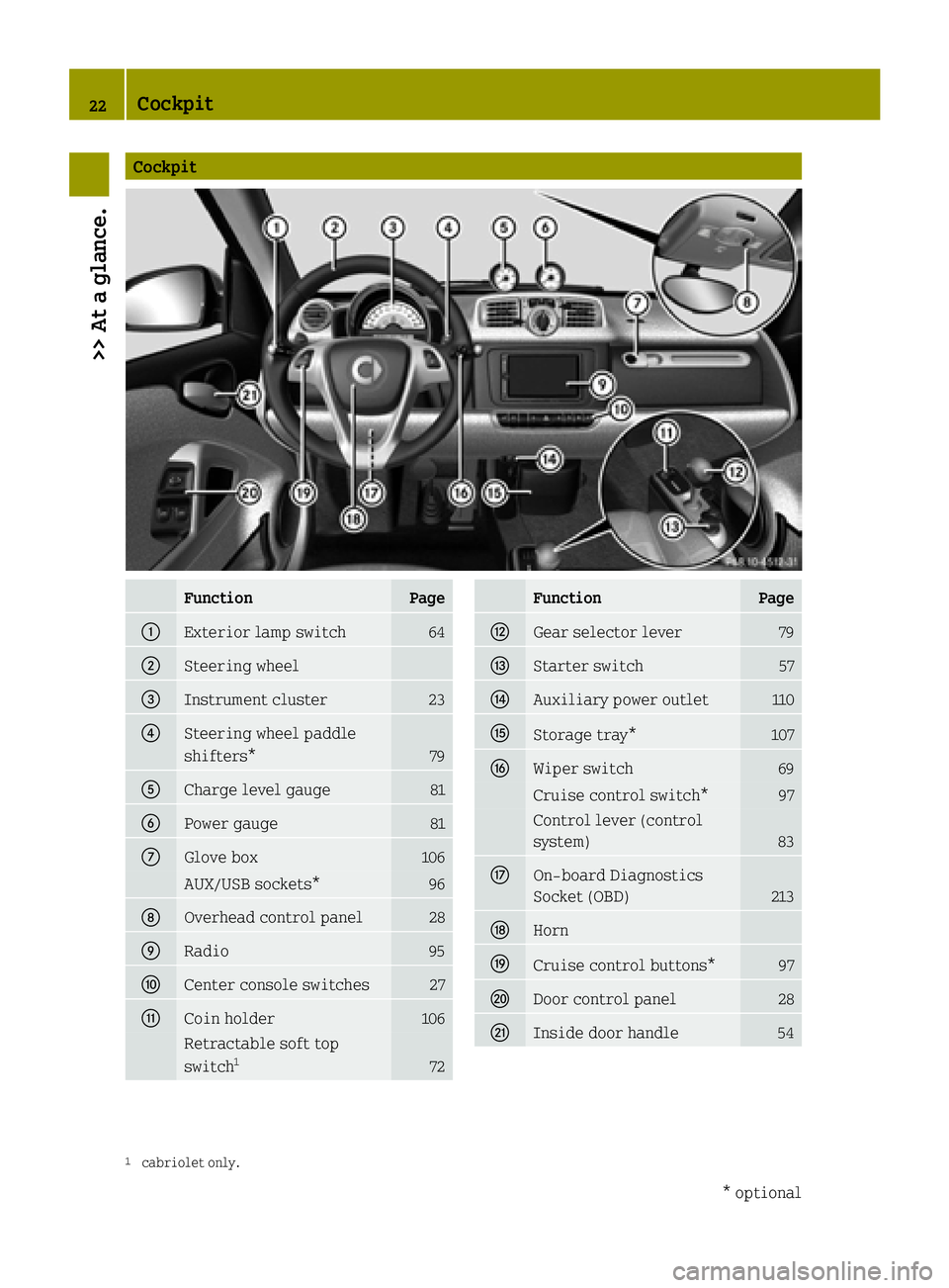
Cockpit
Function Page
:
Exterior lamp switch 64
;
Steering wheel
=
Instrument cluster 23
?
Steering wheel paddle
shifters*
79
A
Charge level gauge 81
B
Power gauge 81
C
Glove box 106
AUX/USB sockets* 96
D
Overhead control panel 28
E
Radio 95
F
Center console switches 27
G
Coin holder 106
Retractable soft top
switch 1 72 Function Page
H
Gear selector lever 79
I
Starter switch 57
J
Auxiliary power outlet 110
K
Storage tray* 107
L
Wiper switch 69
Cruise control switch* 97
Control lever (control
system)
83
M
On-board Diagnostics
Socket (OBD)
213
N
Horn
O
Cruise control buttons* 97
P
Door control panel 28
Q
Inside door handle 54
1
cabriolet only. 22
Cockpit>> At a glance.
* optional
Page 34 of 222
that is as upright as possible and the belt
is properly positioned on the body. G
WARNING
Never let more people ride in the vehicle
than there are seat belts available. Make
sure everyone riding in the vehicle is cor- rectly restrained with a separate seat belt.Never use a seat belt for more than one per-
son at a time. G
WARNING
Seat belts of a vehicle involved in an acci- dent must be inspected by smart. Only then
is it possible to determine whether the seat belts were damaged or stressed in the acci-dent. Damaged or stressed seat belts may
not properly protect you in a subsequent
accident.
Only use seat belts which have been
approved by smart.
Do not make any modifications to the seat
belts. This can lead to unintended activa-
tion of the Emergency Tensioning Devices
(ETDs) or to their failure to activate when
necessary.
Do not bleach or dye seat belts as this may
severely weaken them. In a crash, they may
not be able to provide adequate protection.
Have all work carried out only by qualified
technicians. Contact an authorized elec-
tric drive smart center. G
WARNING
USE SEAT BELTS PROPERLY R Seat belts can only work when used prop-
erly. Never wear seat belts in any other
way than as described in this section, as
that could result in serious injuries in
case of an accident.
R Each occupant should wear their seat belt
at all times, because seat belts help
reduce the likelihood of and potential
severity of injuries in accidents,
including rollovers. The integrated
restraint system includes SRS (driver front air bag, passenger front air bag,
head-thorax air bags) and Emergency
Tensioning Devices (ETDs) with seat belt
force limiters.
The system is designed to enhance the
protection provided by secured seat
belts in certain frontal and side
impacts.
R Never wear the shoulder belt under your
arm, against your neck or off your shoul-
der. Doing so may cause your body to movetoo far forward in a frontal crash, which
would increase the chance of head and
neck injuries. The seat belt would also
apply too much force to the ribs or abdo-
men, which could severely injure inter-
nal organs such as your liver or spleen.
R Never wear seat belts over rigid or
breakable objects in or on your clothing,
such as eyeglasses, pens, keys, etc., as
these might cause injuries.
R Position the lap belt as low as possible
on your hips and not across the abdomen.
If the lap seat belt is positioned across
your abdomen, it could cause serious
injuries in a crash.
R Never use a seat belt for more than one
person at a time. Do not fasten a seat belt
around a person and another person or
other objects at the same time.
R Seat belts should not be worn twisted. In
a crash, you would not have the full width
of the seat belt to manage impact forces. The twisted seat belt against your body
could cause injuries.
R Pregnant women should also always use a
lap-shoulder belt. The lap belt portion
should be positioned as low as possible
on the hips to avoid any possible pres-
sure on the abdomen.
R Never place your feet on the instrument
panel, dashboard or on the seat. Always
keep both feet on the floor in front of the
seat.
R When using a seat belt to secure infant or
toddler restraints or children in booster 32
Occupant safety>> Safety.
Page 37 of 222
continue to provide supplemental crash
protection for occupants.
Safety guidelines for the seat belt,
Emergency Tensioning Devices (ETDs)
and air bag G
WARNING
R Damaged seat belts or seat belts that have
been highly stressed in an accident must
be replaced and their anchoring points
must also be checked. Only use seat belts installed or supplied by an authorized
electric drive smart center.
R Air bags and Emergency Tensioning
Devices (ETDs) contain Perchlorate
material, which may require special
handling and regard for the environment.
Check with your local government’s dis-
posal guidelines. California residents,
see http://www.dtsc.ca.gov/
HazardousWaste/Perchlorate/index.cfm .
R Given the considerable deployment
speed, required inflation volume, and
the textile structure of the air bags,
there is the possibility of abrasions or
other, potentially more serious injuries
resulting from air bag deployment.
R Air bags and Emergency Tensioning
Devices (ETDs) are designed to function
on a one-time-only basis. An air bag or
ETD that has deployed must be replaced.
R Do not pass seat belts over sharp edges.
They could tear.
R Do not make any modification that could
change the effectiveness of the seat
belts.
R No modifications of any kind may be made
to any components or wiring of the SRS.
This includes changing or removing any
component or part of the SRS, the instal-lation of additional trim material,
badges, etc. over the steering wheel hub,
passenger front air bag cover, outboard
sides of the seat backrests, and instal-
lation of additional electrical/elec- tronic equipment on or near SRS compo-
nents and wiring. Keep area between air
bags and occupants free from objects
(e.g. packages, purses, umbrellas, etc.).
R Do not bleach or dye seat belts as this may
severely weaken them. In a crash they may
not be able to provide adequate protec-
tion.
R Do not hang hangers on the coat hooks or
handles over the door. These items may
turn into projectiles and cause head and
other injuries when the head-thorax air
bag is deployed.
R Air bag system components will be hot
after an air bag has inflated. Do not touch
them.
R Never place your feet on the instrument
panel, dashboard, or on the seat. Always
keep both feet on the floor in front of the
seat.
R In addition, improper repair work on the
SRS creates a risk of rendering the SRS
inoperative or causing unintended air
bag deployment. Work on the SRS must
therefore only be performed by qualified
technicians. Contact an authorized elec- tric drive smart center.
R For your protection and the protection of
others, when scrapping the air bag unit
or Emergency Tensioning Devices (ETDs), our safety instructions must be followed.
These instructions are available from
any authorized electric drive smart cen-
ter.
How an air bag operates An air bag is inflated in a matter of mil-
liseconds. If an air bag is triggered, the
SRS indicator lamp
6in the instrument
cluster illuminates.
! If the air bags are activated, you will
hear a loud noise and some dust may be
generated. The explosion fundamentally
represents no risk to your hearing. Occupant safety
35>> Safety. Z
Page 69 of 222
When returning to the vehicle
X
Press button #on the key either once or
twice.
The vehicle is either selectively or
globally unlocked.
The interior lamps come on and then go
out again after 12 seconds. Ambient lighting*
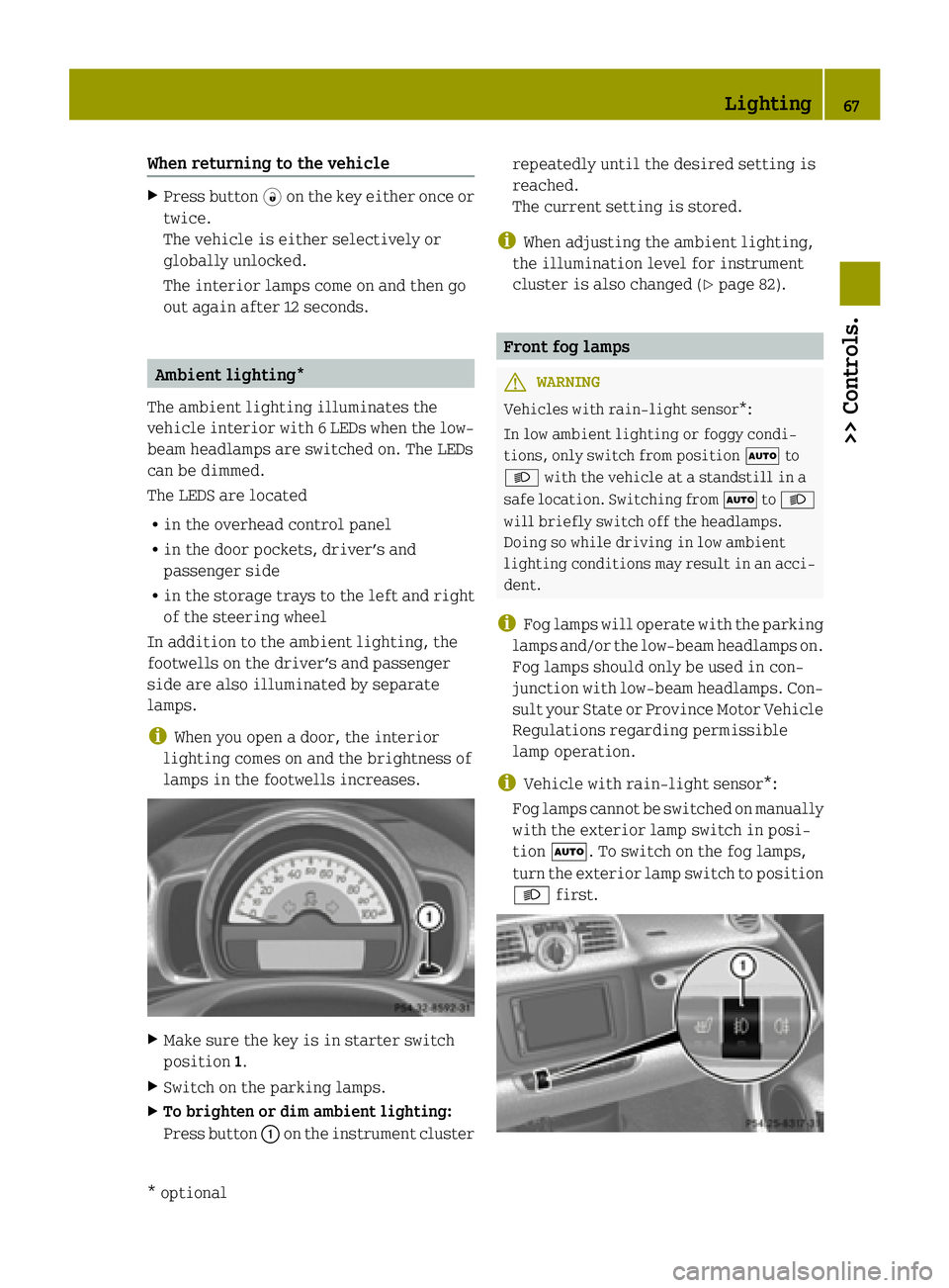
The ambient lighting illuminates the
vehicle interior with 6 LEDs when the low- beam headlamps are switched on. The LEDs
can be dimmed.
The LEDS are located
R in the overhead control panel
R in the door pockets, driver’s and
passenger side
R in the storage trays to the left and right
of the steering wheel
In addition to the ambient lighting, the
footwells on the driver’s and passenger
side are also illuminated by separate
lamps.
i When you open a door, the interior
lighting comes on and the brightness of
lamps in the footwells increases. X
Make sure the key is in starter switch
position 1.
X Switch on the parking lamps.
X To brighten or dim ambient lighting:
Press button :on the instrument cluster repeatedly until the desired setting is
reached.
The current setting is stored.
i When adjusting the ambient lighting,
the illumination level for instrument
cluster is also changed (Y page 82). Front fog lamps
G
WARNING
Vehicles with rain-light sensor*:
In low ambient lighting or foggy condi-
tions, only switch from position Ãto
L with the vehicle at a standstill in a
safe location. Switching from ÃtoL
will briefly switch off the headlamps.
Doing so while driving in low ambient
lighting conditions may result in an acci- dent.
i Fog lamps will operate with the parking
lamps and/or the low‑beam headlamps on.
Fog lamps should only be used in con-
junction with low‑beam headlamps. Con- sult your State or Province Motor Vehicle
Regulations regarding permissible
lamp operation.
i Vehicle with rain-light sensor*:
Fog lamps cannot be switched on manually
with the exterior lamp switch in posi-
tion Ã. To switch on the fog lamps,
turn the exterior lamp switch to position
L first. Lighting
67>> Controls.
* optional Z
Page 84 of 222

Charge level gauge
!
Do not hang any objects on the charge
level gauge.
This could cause the charge level gauge
to be torn from its mountings and be dam-
aged.
The charge level gauge :displays charge
status of the high-voltage battery as a per-
centage.
When the High-voltage Battery at High-voltage Battery at
Reserve Level
Reserve Level message appears in the
multifunction display while the drive sys- tem is in operation, the high-voltage bat-
tery has reached the reserve level.
i If the charge level of the high-voltage
battery has dropped below 20 %, recharge it at:
R an AC power socket (Y page 114)
R a private wall box (Y page 115)
R a public charging station
(Y page 117)
Power gauge G
WARNING
The operating condition of the high-volt-
age battery (e.g. not yet at normal operat-
ing temperature or fully charged) influen- ces the braking effect of the electric
motor.
In overrun or braking mode, the motor's
braking effect may therefore be reduced or
may not be present at all.
As a result of the reduced engine braking
effect, you may cause an accident and
injure yourself or others.
Compensate for the reduced engine braking effect by pressing the brake pedal accord-
ingly, as required.
! Do not hang any objects on the power
gauge.
This could cause the power gauge to be
torn from its mountings and be damaged. Power gauge
;contains two segments:
R Section right of 0
Power gauge ;indicates the current
power that the drive system delivers to
the rear wheels. 100 % correspond to 55 kW peak power.
R Section left of 0
When you release the accelerator pedal
or when you depress the brake pedal, the
electric motor operates as a generator.
Electric current is produced and stored
in the high-voltage battery. As long as
the high-voltage battery is being
charged, the electric motor simulates an
engine brake.
When the pointer of power gauge ;is in
the "OFF“ position, the vehicle is not ready to drive, because:
R the drive system has not been started
R the gear selector lever has not been
moved to position Nor Pwhen starting
the drive system
R the charging cable is connected to the
vehicle
R there is not enough power from the high-
voltage battery
R a problem occured in the high-voltage
system
After the drive system has been started, the pointer of power gauge ;moves to posi-
tion 0.READY
READY appears in the multifunction
display (Y page 87). The vehicle is ready
to drive. Adjusting instrument cluster illumi-
nation
You can adjust the illumination of R the switches and dials in the instrument
cluster
R the radio
R the climate control panel
R the charge level and power gauges
Five illumination levels are available. 82
Instrument cluster>> Controls.
Page 205 of 222
X
Remove the jumper cables from negative terminals =and ?first.
X Remove the jumper cables from positive terminals :and ;.
You can now switch on the headlamps.
X Remount the positive terminal cover.
X Have the 12-volt battery checked at the nearest authorized electric drive smart center.
i Please keep in mind that it will take quite some time to charge the 12-volt battery.
When you switch off the drive system after driving a short distance, you may not be able to start it again.
Charge the 12-volt battery completely as soon as possible. Towing
About towing
This section offers information on towing
methods for breakdown situations and
emergency towing. Recommended towing method - Break-
down situation
! To prevent damage during transport, do
not tie down the vehicle by its chassis or suspension parts — use only wheel straps to position and hold down the vehicle.
Improper tie down on a flatbed carrier
truck or trailer can damage suspension
parts and body panels.
smart recommends that the vehicle be
transported with all wheels off the ground
using a flatbed carrier truck or appropri- ate wheel lift/dolly equipment.
Always have your vehicle transported:
R when the Nwarning lamp for the high-
voltage system lights up in the instru-
ment cluster
R when the Do not tow (away)
Do not tow (away) message
appears in the instrument cluster
R when the multifunction display is inop-
erative R
when one or several of the following
warning lamps light up:
- þ Drive diagnostics (red)
- # 12‑Volt battery
D Power steering
R if the brake pedal already starts to pul-
sate just after towing begins
R if you have to transport the vehicle over
long distances
X Switch off the tow‑away protection* and
interior motion sensor* (Y page 50). Emergency towing
When circumstances do not permit the rec-
ommended towing method, the vehicle may
be towed with all wheels on the ground
using a strap or tow bar connected to
another vehicle. Only tow the vehicle as far as necessary to have the vehicle moved to a
safe location where the recommended tow-
ing method can be employed. G
WARNING
If circumstances require towing the vehi-
cle with all wheels on the ground, always tow
with a tow bar if:
R the drive system will not run
R there is a malfunction in the brake sys-
tem
R there is a malfunction in the power sup-
ply or in the vehicle’s electrical system Towing
203>> Practical hints.
* optional Z