check engine SSANGYONG KORANDO 1997 Service Repair Manual
[x] Cancel search | Manufacturer: SSANGYONG, Model Year: 1997, Model line: KORANDO, Model: SSANGYONG KORANDO 1997Pages: 2053, PDF Size: 88.33 MB
Page 1249 of 2053

AUTOMATIC TRANSMISSION 5A-151
SSANGYONG MY2002
DTC P1746 Solenoid 6 Circuit Short
If diagnosing for a possible intermittent short or
open condition, move or massage the wiring
harness while observing test equipment for a
change.
Test Description
The number(s) below refer to the step number(s) on
the Diagnostic Table.
3. Checks if the S6 circuit in the transmission is mal-
functioning.4. Check cable in the transmission for short to
ground.
6. Check resistance between S6 terminal A and B.
Standard value is 22 - 30 Ω.
9. Check connections of other connectors.
- Go to Step 11 - 1Perform a Transmission Control Module (TCM) System
Check.
Is the check performed?
1. Install the scan tool.
2. Turn the ignition ON, with the engine OFF.
3. Record and then clear DTCs.
4. Operate the vehicle within the conditions for
setting this DTC as specified in the text.
Does the scan tool display P1746?
1. Turn the ignition OFF.
2. Disconnect the 10-way transmission connector.
(additional DTCs will set)
3. Connect Solenoid/Thermistor Electrical Tester
(STET) to the 10-way transmission connector of
transmission side and to the good ground.
4. Turn the mode knob of STET to 6 and push the red
button.
Does the bulb of close circuit on the solenoids side of
STET illuminate?
1. Remove the valve cover. Refer to the Transmission
in this section.
2. With a test light connected to B+, probe the wiring
harness from 10-way transmission connector to
Solenoid 6 (S6) on the valve body.
Does the test light illuminate?
Repair the short to ground in the wiring harness.
Is the repair complete?
Using a Digital Volt Meter (DVM), measure the
resistance between S6 terminal A and B.
Is the resistance within the specified value?
Replace the S6.
Is the action complete?
1. Disconnect the TCM connector A.
2. With a test light connected to B+, probe the wiring
harness from 10-way transmission connector
terminal 6 to TCM terminal A12.
Does the test light illuminate?
Check for a poor connection at the 10-way transmission
connector and TCM connector and repair the malfunc-
tioning terminals as necessary.
Is a repair necessary?
StepAction Value(s) Yes No
2
3
-
Go to Step 2 Go to “TCM
Diagnostic
System Check”
- Go to Step 4 Go to Step 8
5
6 4
- Go to Step 5 Go to Step 6
- Go to Step 11 -
7
8
9
- Go to Step 5 Go to Step 9
- Go to Step 11 Go to Step 10
- Go to Step 3Go to
“Diagnostic
Aids”
20 - 30 ΩGo to
“Diagnostic
Aids” Go to Step 7
Page 1253 of 2053

AUTOMATIC TRANSMISSION 5A-155
SSANGYONG MY2002
DTC P1747 Solenoid 7 Circuit Short
If diagnosing for a possible intermittent short or
open condition, move or massage the wiring
harness while observing test equipment for a
change.
Test Description
The number(s) below refer to the step number(s) on
the Diagnostic Table.
3. Checks if the S7 circuit in the transmission is mal-
functioning.4. Check cable in the transmission for short to
ground.
7. Check resistance between S7 terminal A and B.
Standard value is 22 - 30 Ω.
10. Check connections of other connectors.
- Go to Step 15 Go to Step 7 1Perform a Transmission Control Module (TCM) System
Check.
Is the check performed?
1. Install the scan tool.
2. Turn the ignition ON, with the engine OFF.
3. Record and then clear DTCs.
4. Operate the vehicle within the conditions for
setting this DTC as specified in the text.
Does the scan tool display P1747?
1. Turn the ignition OFF.
2. Disconnect the 10-way transmission connector.
(additional DTCs will set)
3. Connect Solenoid/Thermistor Electrical Tester
(STET) to the 10-way transmission connector of
transmission side and to the good ground.
4. Turn the mode knob of STET to 7 and push the red
button.
Does the bulb of close circuit on the solenoids side of
STET illuminate?
1. Remove the pump assembly. Refer to the Pump in
this section.
2. With a test light connected to B+, probe the wiring
harness from 10-way transmission connector to
contact point attached onto the transmission case.
Does the test light illuminate?
Repair the short to ground in the wiring harness.
Is the repair complete?
With a test light connected to B+, probe the wiring
harness from contact point attached onto the trans-
mission case to S7.
Does the test light illuminate?
Using a Digital Volt Meter (DVM), measure the
resistance between S7 terminal A and B.
Is the resistance within the specified value?
Replace the S7.
Is the action complete?
1. Disconnect the TCM connector A.
2. With a test light connected to B+, probe the wiring
harness from 10-way transmission connector
terminal 7 to TCM terminal A9.
Does the test light illuminate?
StepAction Value(s) Yes No
2
3
-
Go to Step 2 Go to “TCM
Diagnostic
System Check”
- Go to Step 4 Go to Step 8
5
6 4
- Go to Step 5 Go to Step 6
- Go to Step 12 -
7
8
9
- Go to Step 12 -
- Go to Step 5 Go to Step 10
- Go to Step 3Go to
“Diagnostic
Aids”
20 - 30 ΩGo to
“Diagnostic
Aids”
Go to Step 8
Page 1255 of 2053

5A-160 AUTOMATIC TRANSMISSION
SSANGYONG MY2002
UNIT REPAIR
REBUILD WARNINGS
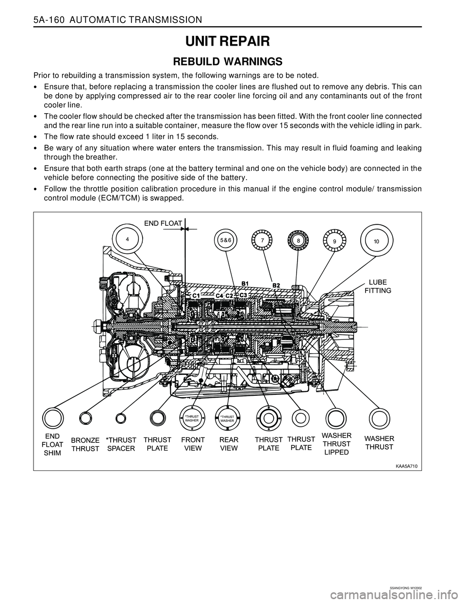
Prior to rebuilding a transmission system, the following warnings are to be noted.
Ensure that, before replacing a transmission the cooler lines are flushed out to remove any debris. This can
be done by applying compressed air to the rear cooler line forcing oil and any contaminants out of the front
cooler line.
The cooler flow should be checked after the transmission has been fitted. With the front cooler line connected
and the rear line run into a suitable container, measure the flow over 15 seconds with the vehicle idling in park.
The flow rate should exceed 1 liter in 15 seconds.
Be wary of any situation where water enters the transmission. This may result in fluid foaming and leaking
through the breather.
Ensure that both earth straps (one at the battery terminal and one on the vehicle body) are connected in the
vehicle before connecting the positive side of the battery.
Follow the throttle position calibration procedure in this manual if the engine control module/ transmission
control module (ECM/TCM) is swapped.
KAA5A710
Page 1312 of 2053

SSANGYONG MY2002
5B-4 MANUAL TRANSMISSION
DIAGNOSTIC INFORMATION AND PROCEDURES
Control lever assembly broken or dam-
aged.
Damaged offset lever, shift fork, selector
place or selector arm.
Clutch not releasing.
Improper or low transmission oil.
Shift or shift rail binding.
Binding of sliding synchronizers or gears.
If reverse only, faulty backup switch.
Worn or damaged flywheel pilot bushing.
Engine idle speed too high.
Damaged or faulty clutch.
Pilot bearing between input shaft and
output shaft binding.
Damaged synchronizer.
Bell housing misaligned.
Damaged gear(s).
Worn or damaged flywheel pilot bushing.
Loosened transmission or flywheel
housing bolts, improper alignment.
Synchronizer damaged or excessively
worn.
Blocking ring damaged, worn index slots
or friction surfaces worn or damaged.
Excessive countershaft end play.
Worn or damaged fork due to loosened
shaft, rail or shifting fork.
Fork or offset lever loose on shaft or rail.
Worn or damaged forks, offset lever,
shaft or rail.Replace control lever and housing assem-
bly.
Remove extension, adapter or case
cover. Check or replace damaged parts.
Adjust or replace clutch.
Add or replace with specified oil.
Remove extension, adapter or case
cover. Check or replace damaged parts.
Remove extension, adapter or case
cover. Check synchronizers and gears
and replace damaged parts.
Check or replace backup switch.
Replace pilot bushing.
Adjust idle speed to specified speed.
Adjust or replace clutch.
Replace or check roller bearings.
Check or replace synchronizer parts.
Align bell housing and bore.
Check or replace gear(s).
Replace pilot bushing.
Tighten bolts to specified value. Realign
if necessary.
Check or replace synchronizer parts.
Check or replace blocking ring.
Check worn or damaged parts. Adjust
shim thickness using roller bearings if
necessary.
Check for wear or damaged. Replace
worn or damaged parts.
Replace extension, adapter or case
cover. Check or replace loose parts on
shaft or rail. Replace roll pin(s).
Remove extension, adapter or case
cover. Check for wear or damaged.
Replace damaged parts. Check Applicatio
Will not shift
(control lever moves)
Hard shift or control
lever will not move into
gear
Gears crash when
shifting
Transmission jumps
out
Transmission locked in
one gear
Action
Page 1313 of 2053

MANUAL TRANSMISSION 5B-5
SSANGYONG MY2002
Check worn or damaged synchronizer
parts and replace if necessary.
Check worn or damaged gears and
replace if necessary.
Add or drain and replace with proper oil.
Tighten as specified.
Realign correctly.
Check bearings, bearing rollers and parts
for wear or damage. Replace if neces-
sary.
Check for worn or damaged
gears(including speedometer gear).
Replace if necessary.
Clean all exposed surfaces, then check
for leaks.
Clean or replace vent or breather.
Check oil level.
Tighten as specified.
Clean leaking surfaces. Reapply sealant.
Replace oil seal.
Action
Worn or damaged synchronizer.
Worn or damaged gears.
Improper or low transmission oil.
Loose bolts or other attaching parts.
Improper flywheel housing to engine
crankshaft alignment.
Noisy transmission bearing.
Noisy gears.
Leakage from transmission.
Vent or breather clogged.
Too much oil.
Loose bolts at sealing faces.
Improperly applied sealant.
Worn or damaged oil seal.Check Applicatio
Transmission locked in
one gear
Transmission noise
Transmission leakage
Page 1330 of 2053

SSANGYONG MY2002
5B-22 MANUAL TRANSMISSION
62 - 93 Nm
(45 - 69 lb-ft)
21 - 35 Nm
(15 - 26 lb-ft)
Check the housing face alignment.
- Place the dial indicator on the housing face.
- By rotating the crankshaft one revolution,
record the dial indicator reading.
Notice: If the reading is greater than 0.010 inch,
insert the shim between the engine and clutch
housing and adjust the alignment.
5. Check the following parts :
Pressure plate spring assembly
Disc
Flywheel
Input shaft pilot bearing
Notice: Replace the excessively worn parts.
6. Lubricate the clutch release bearing bore, fork
pivot head during assembly.
Installation Procedure
1. Install the transmission to the vehicle. At this time,
seat correctly the input shaft of the transmission
on the pilot bearing of the flywheel.
2. Tighten the transmission mounting bolts as the
specified torque on the vehicle.
Installation Notice
YAD5B390
YAD5B400
YAD5B410
YAD5B420
Tightening Torque77 - 87 Nm
(57 - 64 lb-ft)
3. Install the cross member and tighten as the
specified torque by supporting the suitable jack.
Installation Notice
Tightening
TorqueLeft/Right
Center
Page 1369 of 2053

CLUTCH 5C-15
SSANGYONG MY2002
Replace
Repair or Replace
Replace
Replace
Adjust
Repair or Replace
Replace Excessive Wear of Facing
Hard or Oily Facing
Damaged Pressure Plate or Flywheel
Damaged or Burnt Diaphragm Spring
Clutch Pedal Free play Insufficient
Faulty Operation of Clutch Pedal
Worn or Damaged Clutch DiscAction Checks
DIAGNOSIS
CLUTCH SLIPS
Replace
Repair or Replace
Repair or Replace
Replace
Adjust Vibration or Excessive Run-out of Disc
Rust or Wear of Disc Spline
Oily Facing
Damaged Diaphragm Spring
Excessive Clutch Pedal Free playAction Checks
POOR DISENGAGEMENT
Adjust Pedal Freeplay
Repair Release Cylinder
Repair or Replace
Repair as Necessary
Replace Excessive Clutch Pedal Free play
Faulty Clutch Release Cylinder
Worn Disc, Excessive Run-out, Damaged Lining
Dirty or Burred Splines on Input Shaft or Clutch Disc
Damaged Clutch Pressure PlateAction Checks
HARD TO SHIFT OR WILL NOT SHIFT
Repair or Replace
Replace
Replace
Replace
Replace
Repair or Replace
Tighten or Replace Oily Facing
Hard or Faulty Facing
Burnt Torsion Spring
Faulty Pressure Plate
Bent Clutch Diaphragm Spring
Hard or Bent Flywheel
Engine Mounts Loose or Burnt LeverAction Checks
CLUTCH CHATTERS WHEN STARTING
Page 1446 of 2053

SSANGYONG MY2002
6A-4 POWER STEERING SYSTEM
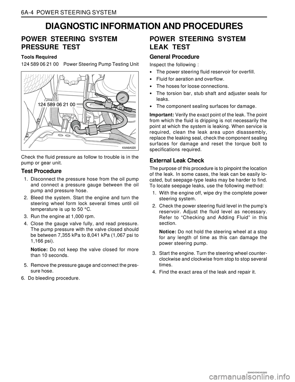
KAA6A020
DIAGNOSTIC INFORMATION AND PROCEDURES
POWER STEERING SYSTEM
PRESSURE TEST
Tools Required
124 589 06 21 00 Power Steering Pump Testing Unit
Check the fluid pressure as follow to trouble is in the
pump or gear unit.
Test Procedure
1. Disconnect the pressure hose from the oil pump
and connect a pressure gauge between the oil
pump and pressure hose.
2. Bleed the system. Start the engine and turn the
steering wheel form lock several times until oil
temperature is up to 50 °C.
3. Run the engine at 1,000 rpm.
4. Close the gauge valve fully, and read pressure.
The pump pressure with the valve closed should
be between 7,355 kPa to 8,041 kPa (1,067 psi to
1,166 psi).
Notice: Do not keep the valve closed for more
than 10 seconds.
5. Remove the pressure gauge and connect the pres-
sure hose.
6. Do bleeding procedure.
POWER STEERING SYSTEM
LEAK TEST
General Procedure
Inspect the following :
The power steering fluid reservoir for overfill.
Fluid for aeration and overflow.
The hoses for loose connections.
The torsion bar, stub shaft and adjuster seals for
leaks.
The component sealing surfaces for damage.
Important: Verify the exact point of the leak. The point
from which the fluid is dripping is not necessarily the
point at which the system is leaking. When service is
required, clean the leak area upon disassembly,
replace the leaking seal, check the component sealing
surfaces for damage and reset the torque bolt to
specifications required.
External Leak Check
The purpose of this procedure is to pinpoint the location
of the leak. In some cases, the leak can be easily lo-
cated, but seepage-type leaks may be harder to find.
To locate seepage leaks, use the following method:
1. With the engine off, wipe dry the complete power
steering system.
2. Check the power steering fluid level in the pump’s
reservoir. Adjust the fluid level as necessary.
Refer to “Checking and Adding Fluid” in this
section.
Notice: Do not hold the steering wheel at a stop
for any length of time as this can damage the
power steering pump.
3. Start the engine. Turn the steering wheel counter-
clockwise and clockwise from stop to stop several
times.
4. Find the exact area of the leak and repair it.
Page 1447 of 2053

POWER STEERING SYSTEM 6A-5
SSANGYONG MY2002
BLEEDING THE POWER
STEERING SYSTEM
1. Disconnect the fuel line. Using a starter motor,
crank the engine and turn the steering wheel from
lock to start 5 or 6 times.
Notice: Do bleeding with engine cranking. If bleed
with idling, there can be a air contact with oil.
2. Connect the fuel feed line and start the engine at
idle speed.
3. Turn the steering wheel from lock to lock until there
is no more air in oil reservoir.
4. Connect the oil level is within specification.
5. By turning the steering wheel left to right, check
the oil level change.
Notice: If oil is not changes more than 5 mm, do
bleeding again. If oil level rises suddenly when
stopped engine, again.
MAINTENANCE
CHECKING AND ADDING FLUID
Notice: When adding fluid or making a complete fluid
change, always use DEXRON. - II power steering fluid.
Failure to use the proper fluid will cause hose and seal
damage and fluid leaks.
1. The power steering fluid level is indicated by marks
on a fluid level indicator on the fluid reservoir cap.
2. If the fluid is warmed up to 66 °C (150 °F), the fluid
level should be between the MAX and MIN marks.
Add fluid as needed.
3. If the fluid is cool, 21 °C (70 °F), the fluid level should
be at the MIN mark. Add fluid as needed.
Page 1455 of 2053

SSANGYONG MY2002
6A-4 POWER STEERING SYSTEM
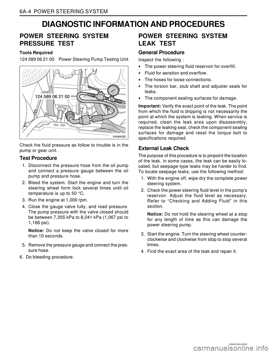
KAA6A020
DIAGNOSTIC INFORMATION AND PROCEDURES
POWER STEERING SYSTEM
PRESSURE TEST
Tools Required
124 589 06 21 00 Power Steering Pump Testing Unit
Check the fluid pressure as follow to trouble is in the
pump or gear unit.
Test Procedure
1. Disconnect the pressure hose from the oil pump
and connect a pressure gauge between the oil
pump and pressure hose.
2. Bleed the system. Start the engine and turn the
steering wheel form lock several times until oil
temperature is up to 50 °C.
3. Run the engine at 1,000 rpm.
4. Close the gauge valve fully, and read pressure.
The pump pressure with the valve closed should
be between 7,355 kPa to 8,041 kPa (1,067 psi to
1,166 psi).
Notice: Do not keep the valve closed for more
than 10 seconds.
5. Remove the pressure gauge and connect the pres-
sure hose.
6. Do bleeding procedure.
POWER STEERING SYSTEM
LEAK TEST
General Procedure
Inspect the following :
The power steering fluid reservoir for overfill.
Fluid for aeration and overflow.
The hoses for loose connections.
The torsion bar, stub shaft and adjuster seals for
leaks.
The component sealing surfaces for damage.
Important: Verify the exact point of the leak. The point
from which the fluid is dripping is not necessarily the
point at which the system is leaking. When service is
required, clean the leak area upon disassembly,
replace the leaking seal, check the component sealing
surfaces for damage and reset the torque bolt to
specifications required.
External Leak Check
The purpose of this procedure is to pinpoint the location
of the leak. In some cases, the leak can be easily lo-
cated, but seepage-type leaks may be harder to find.
To locate seepage leaks, use the following method:
1. With the engine off, wipe dry the complete power
steering system.
2. Check the power steering fluid level in the pump’s
reservoir. Adjust the fluid level as necessary.
Refer to “Checking and Adding Fluid” in this
section.
Notice: Do not hold the steering wheel at a stop
for any length of time as this can damage the
power steering pump.
3. Start the engine. Turn the steering wheel counter-
clockwise and clockwise from stop to stop several
times.
4. Find the exact area of the leak and repair it.