oil filter SSANGYONG KORANDO 1997 Service Owner's Manual
[x] Cancel search | Manufacturer: SSANGYONG, Model Year: 1997, Model line: KORANDO, Model: SSANGYONG KORANDO 1997Pages: 2053, PDF Size: 88.33 MB
Page 294 of 2053
D AEW OO M Y_2000
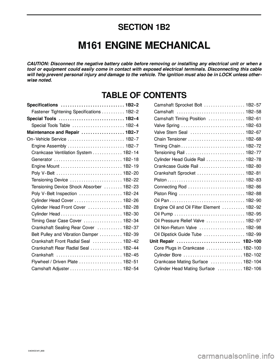
SECTION 1B2
M161 ENGINE MECHANICAL
CAUTION: Disconnect the negative battery cable before removing or installing any electrical unit or when a
tool or equipment could easily come in contact with exposed electrical terminals. Disconnecting this cable
will help prevent personal injury and damage to the vehicle. The ignition must also be in LOCK unless other -
wise noted.
TABLE OF CONTENTS
Specifications 1B2 -- 2............................
Fastener Tightening Specifications 1B2 -- 2..........
Special Tools 1B2 -- 4.............................
Special Tools Table 1B2-- 4.......................
Maintenance and Repair 1B2 -- 7...................
On-- Vehicle Service 1B2-- 7.........................
Engine Assembly 1B2-- 7.........................
Crankcase Ventilation System 1B2-- 14.............
Generator 1B2-- 18..............................
Engine Mount 1B2-- 19...........................
Poly V-- Belt 1B2 -- 20.............................
Tensioning Device 1B2-- 22.......................
Tensioning Device Shock Absorber 1B2-- 23........
Poly V-- Belt Inspection 1B2-- 24...................
Cylinder Head Cover 1B2-- 26.....................
Cylinder Head Front Cover 1B2 -- 28...............
Cylinder Head 1B2-- 30...........................
Timing Gear Case Cover 1B2-- 34.................
Crankshaft Sealing Rear Cover 1B2-- 37...........
Belt Pulley and Vibration Damper 1B2-- 39..........
Crankshaft Front Radial Seal 1B2-- 42.............
Crankshaft Rear Radial Seal 1B2-- 44..............
Crankshaft 1B2-- 45.............................
Flywheel / Driven Plate 1B2 -- 51...................
Camshaft Adjuster 1B2-- 54.......................Camshaft Sprocket Bolt 1B2-- 57..................
Camshaft 1B2-- 58..............................
Camshaft Timing Position 1B2 -- 61................
Valve Spring 1B2 -- 63............................
Valve Stem Seal 1B2-- 67........................
Chain Tensioner 1B2-- 68.........................
Timing Chain 1B2-- 72............................
Tensioning Rail 1B2-- 77..........................
Cylinder Head Guide Rail 1B2-- 78.................
Crankcase Guide Rail 1B2-- 80....................
Crankshaft Sprocket 1B2-- 81.....................
Piston 1B2-- 83..................................
Connecting Rod 1B2-- 86.........................
Piston Ring 1B2 -- 88.............................
Oil Pan 1B2-- 90.................................
Engine Oil and Oil Filter Element 1B2-- 92..........
Oil Pump 1B2-- 95...............................
Oil Pressure Relief Valve 1B2-- 97.................
Oil Non-Return Valve 1B2-- 98....................
Oil Dipstick Guide Tube 1B2-- 99..................
Unit Repair 1B2 -- 100............................
Core Plugs in Crankcase 1B2-- 100................
Cylinder Bore 1B2-- 102..........................
Crankcase Mating Surface 1B2-- 104..............
Cylinder Head Mating Surface 1B2-- 106...........
Page 296 of 2053
M161 ENGINE MECHANICAL 1B2 -- 3
D AEW OO M Y_2000
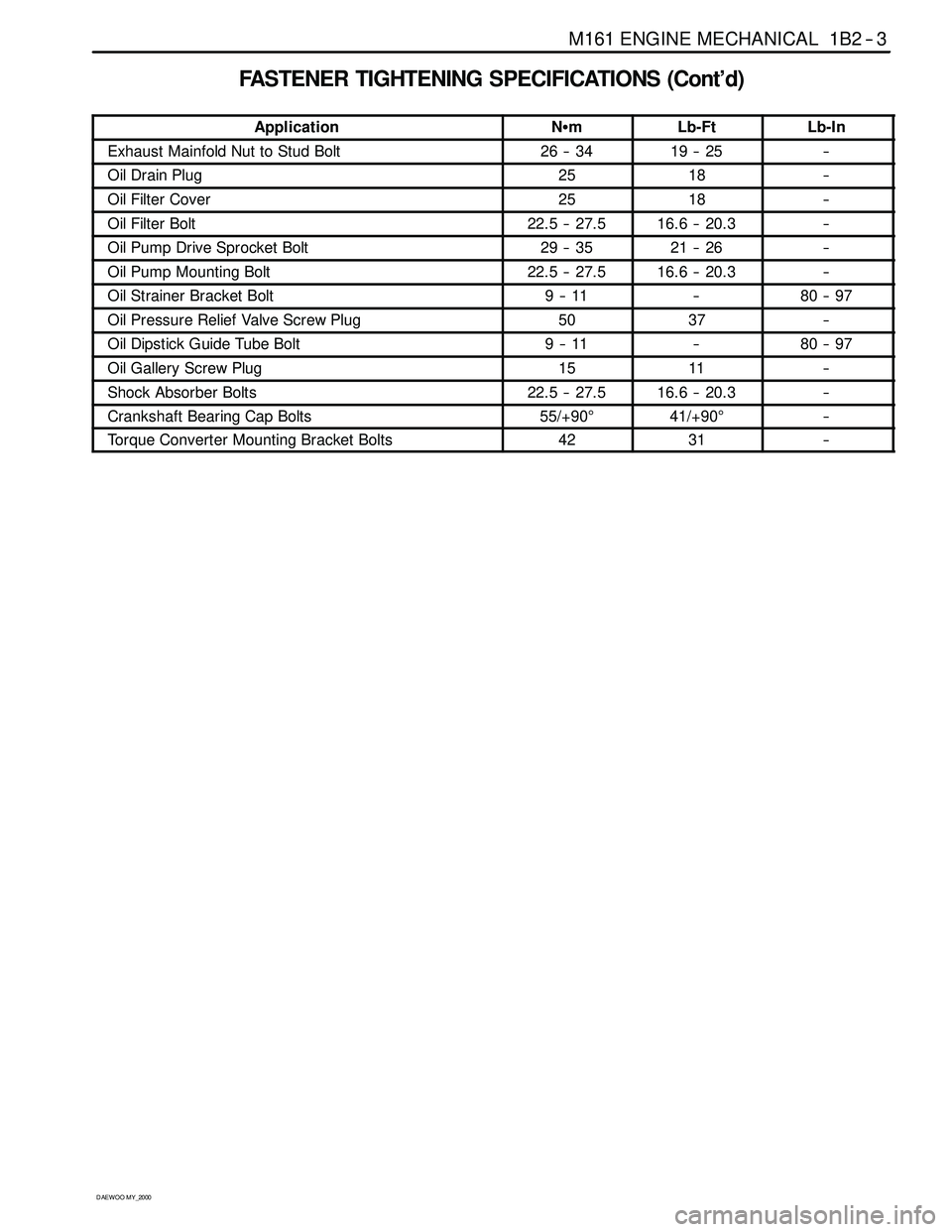
FASTENER TIGHTENING SPECIFICATIONS (Cont’d)
ApplicationNSmLb-FtLb-In
Exhaust Mainfold Nut to Stud Bolt26 -- 3419 -- 25--
Oil Drain Plug2518--
Oil Filter Cover2518--
Oil Filter Bolt22.5 -- 27.516.6 -- 20.3--
Oil Pump Drive Sprocket Bolt29 -- 3521 -- 26--
Oil Pump Mounting Bolt22.5 -- 27.516.6 -- 20.3--
Oil Strainer Bracket Bolt9--11--80 -- 97
Oil Pressure Relief Valve Screw Plug5037--
Oil Dipstick Guide Tube Bolt9--11--80 -- 97
Oil Gallery Screw Plug1511--
Shock Absorber Bolts22.5 -- 27.516.6 -- 20.3--
Crankshaft Bearing Cap Bolts55/+90°41/+90°--
Torque Converter Mounting Bracket Bolts4231--
Page 297 of 2053

1B2 -- 4 M161 ENGINE MECHANICAL
D AEW OO M Y_2000
SPECIAL TOOLS
SPECIAL TOOLS TABLE
000 589 58 43 00
Chain Assembly
111 589 01 59 00
Supporting Bar
111 589 18 61 00
Lever Pusher
116 589 01 34 00
Threaded Pin
103 589 02 09 00
Oil Filter Remover
111 589 25 63 00
Thrust Piece
116 589 20 33 00
Sliding Hammer
119 589 00 43 00
Drift
Page 327 of 2053

1B2 -- 34 M161 ENGINE MECHANICAL
D AEW OO M Y_2000
TIMING GEAR CASE COVER
Preceding Work: Removal of viscous clutch
Removal of cylinder head front cover
Removal of tensioning device
Removal of water pump
Removal of oil filter element
Removal of oil pan
Removal of generator bracket
1 Bolt (M8 X 60, 3 pieces)
22.5-- 27.5 NSm (16.6-- 20.3 lb-ft) .............
2 Bolt (M8 X 75, 1 piece)
22.5-- 27.5 NSm (16.6-- 20.3 lb-ft) .............3Seal
4 Timing gear case cover
5O--ring
6 Sleeve
Page 384 of 2053

M161 ENGINE MECHANICAL 1B2 -- 91
D AEW OO M Y_2000
Oil Circulation
1 Oil Strainer
2OilPump
3OilPan
4 Oil Non-- Return Valve
5 Oil Filter
6 Oil Filter Bypass Valve
7 Main Oil Gallery
8 Closing Ball (φ15mm)
9 Crankshaft
10 Connecting Rod Bearing
11 Crankshaft Bearing
12 Connecting Rod
13 Piston
14 Oil Spray (Piston Crown Area)
15 Non-- Return Valve (Crankcase)16 Oil Supply (To Chain Tensioner)
17 Camshaft
18 Cam Bearing
19 Valve
20 Oil Gallery (Supply Oil to Intake Tappet)
21 Oil Gallery (Supply Oil to Exhaust Tappet)
22 Ball (φ8mm)
23 Camshaft Plug
24 Seal
25 Screw Plug
26 Oil Return Gallery
(Cylinder Head and Crankcase)
27 Oil Return Gallery (Crankcase)
28 End Cover (φ20mm)
29 Oil Return Pipe
Page 423 of 2053

D AEW OO M Y_2000
SECTION 1F2
ENGINE CONTROLS
CAUTION: Disconnect the negative battery cable before removing or installing any electrical unit or when a
tool or equipment could easily come in contact with exposed electrical terminals. Disconnecting this cable
will help prevent personal injury and damage to the vehicle. The ignition must also be in LOCK unless other -
wise noted.
TABLE OF CONTENTS
Engine and ECM Problem Check Report 1F2 -- 2....
Specifications 1F2 -- 3............................
Engine Data Display Table 1F2 -- 3.................
Fastener Tightening Specifications 1F2 -- 4..........
Fuel System Specification 1F2 -- 5.................
Temperature vs Resistance 1F2 -- 5................
Special Tools and Equipment 1F2 -- 6..............
Special Tools Table 1F2 -- 6.......................
Schematic and Routing Diagrams 1F2 -- 7..........
ECM Wiring Diagram
(2.3L DOHC -- MSE 3.53S) 1F2 -- 7..............
Diagnosis 1F2 -- 14................................
Failure Code Diagnosis 1F2 -- 14.....................
Clearing Failure Codes 1F2 -- 14...................
Failure Codes Table 1F2 -- 14.....................
Ignition System 1F2 -- 18...........................
Ignition Coil 1F2 -- 20.............................
Crankshaft Position (CKP) Sensor 1F2 -- 22.........
Camshaft Position (CMP) Sensor 1F2 -- 26..........
Camshaft Actuator 1F2 -- 30......................
Knock Sensor (KS) 1F2 -- 32......................
Spark Plug 1F2 -- 34.............................
System Voltage 1F2 -- 38.........................
Ignition Switch 1F2 -- 39..........................
Fuel System 1F2 -- 40..............................
Fuel Pump 1F2 -- 42.............................
Fuel Injector 1F2 -- 46............................
Purge Control Valve 1F2 -- 50.....................
Fuel Rail 1F2 -- 52...............................
Fuel Pressure Regulator 1F2 -- 54.................
Induction System 1F2 -- 56..........................
Throttle Valve Actuator 1F2 -- 56...................
Hot Film Air Mass (HFM) Sensor 1F2 -- 60..........
Engine Coolant Temperature (ECT) Sensor 1F2 -- 64.
Accelerator Pedal Module 1F2 -- 68................Cooling Fan 1F2 -- 72............................
A/C Compressor Relay 1F2 -- 73...................
Cruise Control Switch 1F2 -- 74....................
Traction Control System (TCS) 1F2 -- 75............
Stop Lamp Switch 1F2 -- 76.......................
Engine RPM 1F2 -- 77............................
Exhaust System 1F2 -- 78...........................
Catalytic Converter 1F2 -- 78......................
Oxygen Sensor 1F2 -- 80.........................
Engine Control Module 1F2 -- 86.....................
Serial Data Communication 1F2--88...............
Internal Failure 1F2 -- 90..........................
Electronic Throttle Controller Safety
Malfunction 1F2 -- 92...........................
Immobilizer 1F2 -- 94.............................
Maintenance and Repair 1F2 -- 95..................
On -- Vehicle Service 1F2 -- 95........................
Discharging the Pressure in Fuel System 1F2 -- 95...
Fuel Pump 1F2 -- 95.............................
Fuel Filter 1F2 -- 96..............................
Fuel Tank 1F2 -- 97..............................
Fuel Pressure Regulator 1F2 -- 98.................
Fuel Rail and Injector 1F2 -- 99....................
Engine Coolant Temperature Sensor 1F2 -- 100......
Throttle Body (Integrated with the
Actuator) 1F2 -- 101............................
Hot Film Air Mass (HFM) Sensor 1F2 -- 102.........
Knock Sensor 1F2 -- 102..........................
Pedal Position Sensor 1F2 -- 103...................
Oxygen Sensor 1F2 -- 103........................
Purge Control Valve 1F2 -- 104....................
Canister 1F2 -- 104...............................
Camshaft Position Sensor 1F2 -- 104...............
Crankshaft Position Sensor 1F2 -- 105..............
Engine Control Module 1F2 -- 105..................
Page 537 of 2053

1A3 -- 2 GENERAL ENGINE INFORMATION
D AEW OO M Y_2000
ENGINE SPECIFICATIONS (Cont’d)
ApplicationOM662LAOM661LA
Idle Speed (rpm)720 -- 820750 -- 850
Fuel Injection Pressure (bar)135 -- 143135 -- 143
Oil Capacity (liter)8.0 -- 9.56.5 -- 8.0
Lubrication TypeForced by Gear PumpForced by Gear Pump
Oil Filter TypeCombined Full-- Flow and Partial
Flow FilterCombined Full-- Flow and Partial
Flow Filter
FuelDieselDiesel
Page 551 of 2053
D AEW OO M Y_2000
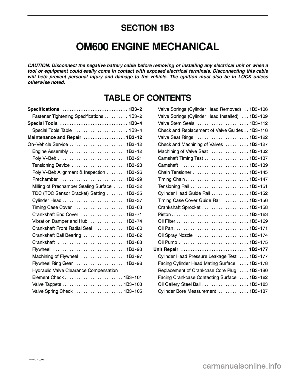
SECTION 1B3
OM600 ENGINE MECHANICAL
CAUTION: Disconnect the negative battery cable before removing or installing any electrical unit or when a
tool or equipment could easily come in contact with exposed electrical terminals. Disconnecting this cable
will help prevent personal injury and damage to the vehicle. The ignition must also be in LOCK unless
otherwise noted.
TABLE OF CONTENTS
Specifications 1B3 -- 2............................
Fastener Tightening Specifications 1B3 -- 2..........
Special Tools 1B3 -- 4.............................
Special Tools Table 1B3-- 4.......................
Maintenance and Repair 1B3 -- 12..................
On-- Vehicle Service 1B3-- 12........................
Engine Assembly 1B3-- 12........................
Poly V-- Belt 1B3 -- 21.............................
Tensioning Device 1B3-- 23.......................
Poly V-- Belt Alignment & Inspection 1B3-- 26........
Prechamber 1B3-- 29............................
Milling of Prechamber Sealing Surface 1B3 -- 32.....
TDC (TDC Sensor Bracket) Setting 1B3 -- 35........
Cylinder Head 1B3-- 37...........................
Timing Case Cover 1B3 -- 63......................
Crankshaft End Cover 1B3-- 71...................
Vibration Damper and Hub 1B3-- 74...............
Crankshaft Front Radial Seal 1B3-- 80.............
Crankshaft Ball Bearing 1B3-- 82..................
Crankshaft 1B3-- 83.............................
Flywheel 1B3 -- 93...............................
Machining of Flywheel 1B3-- 97...................
Flywheel Ring Gear 1B3 -- 98......................
Hydraulic Valve Clearance Compensation
Element Check 1B3-- 101.........................
Valve Tappets 1B3-- 103..........................
Valve Spring Check 1B3-- 105.....................Valve Springs (Cylinder Head Removed) 1B3-- 106..
Valve Springs (Cylinder Head Installed) 1B3-- 109...
Valve Stem Seals 1B3-- 112......................
Check and Replacement of Valve Guides 1B3-- 116..
Valve Seat Rings 1B3-- 122.......................
Check and Machining of Valves 1B3-- 127..........
Machining of Valve Seat 1B3-- 132.................
Camshaft Timing Test 1B3-- 137...................
Camshaft 1B3-- 139.............................
Chain Tensioner 1B3-- 145........................
Timing Chain 1B3-- 147...........................
Tensioning Rail 1B3-- 151.........................
Cylinder Head Guide Rail 1B3-- 152................
Timing Case Cover Guide Rail 1B3-- 156...........
Crankshaft Sprocket 1B3-- 158....................
Piston 1B3-- 163.................................
Oil Filter 1B3-- 169...............................
Oil Pan 1B3-- 171................................
Oil Spray Nozzle 1B3-- 174.......................
Oil Pump 1B3-- 175..............................
Unit Repair 1B3 -- 177............................
Cylinder Head Pressure Leakage Test 1B3-- 177....
Facing Cylinder Head Mating Surface 1B3 -- 178.....
Replacement of Crankcase Core Plug 1B3-- 180.....
Facing Crankcase Contacting Surface 1B3 -- 182....
Oil Gallery Steel Ball 1B3-- 183....................
Cylinder Bore Measurement 1B3-- 187.............
Page 553 of 2053
OM600 ENGINE MECHANICAL 1B3 -- 3
D AEW OO M Y_2000
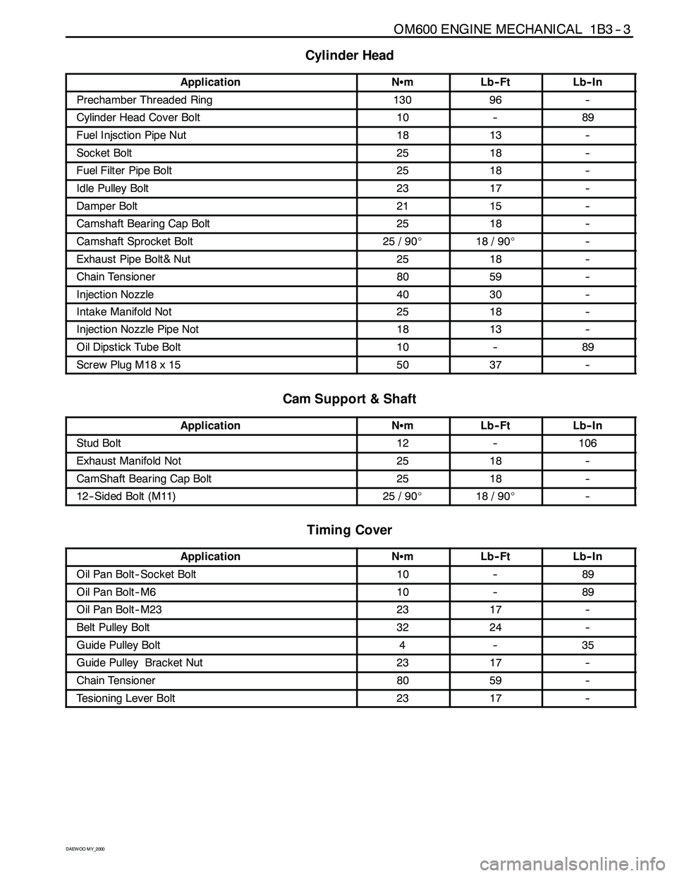
Cylinder Head
ApplicationNSmLb-- FtLb-- In
Prechamber Threaded Ring13096--
Cylinder Head Cover Bolt10--89
Fuel Injsction Pipe Nut1813--
Socket Bolt2518--
Fuel Filter Pipe Bolt2518--
Idle Pulley Bolt2317--
Damper Bolt2115--
Camshaft Bearing Cap Bolt2518--
Camshaft Sprocket Bolt25 / 90_18 / 90_--
Exhaust Pipe Bolt& Nut2518--
Chain Tensioner8059--
Injection Nozzle4030--
Intake Manifold Not2518--
Injection Nozzle Pipe Not1813--
Oil Dipstick Tube Bolt10--89
Screw Plug M18 x 155037--
Cam Support & Shaft
ApplicationNSmLb-- FtLb-- In
Stud Bolt12--106
Exhaust Manifold Not2518--
CamShaft Bearing Cap Bolt2518--
12-- Sided Bolt (M11)25 / 90_18 / 90_--
Timing Cover
ApplicationNSmLb-- FtLb-- In
Oil Pan Bolt -- Socket Bolt10--89
Oil Pan Bolt--M610--89
Oil Pan Bolt--M232317--
Belt Pulley Bolt3224--
Guide Pulley Bolt4--35
Guide Pulley Bracket Nut2317--
Chain Tensioner8059--
Tesioning Lever Bolt2317--
Page 565 of 2053

1B3 -- 16 OM600 ENGINE MECHANICAL
D AEW OO M Y_2000
16. Remove the power steering pump lines.
Notice
Completely drain the fluid.
17. Disconnect the fuel feed line with prefilter from the
feed pump on injection pump.
18. Vehicle with automatic transmission.
Remove the hydraulic lines (19, 20) from oil cooler
(2).
19. Disconnect the engine harness.
20. Disconnect the preheating time relay cable.