warning SSANGYONG KORANDO 1997 Service Owner's Guide
[x] Cancel search | Manufacturer: SSANGYONG, Model Year: 1997, Model line: KORANDO, Model: SSANGYONG KORANDO 1997Pages: 2053, PDF Size: 88.33 MB
Page 1053 of 2053

SSANGYONG MY2002
4F-70 ABS AND TCS
DIAGNOSTIC TROUBLE CODE (DTC) 21/22
LEFT REAR PRIME LINE AND TRACTION CONTROL
SYSTEM (TCS) PILOT VALVE FAULT
KAA4F200
Circuit Description
The solenoid valve coil circuits are supplied with power
from the battery when the valve relay is energized.
Switched ground is provided by the electronic brake
control module (EBCM) to each coil.
Diagnosis
This procedure checks whether the left rear TCS valves
are functioning.Cause(s)
A solenoid coil is open or shorted.
Fail Action
Antilock brake system (ABS) is disabled, and the ABS
warning lamp is turned ON for the remainder of the
ignition cycle. If the failure is intermittent, the EBCM
will enable the system at the next ignition cycle and
set a history DTC.
Page 1055 of 2053

SSANGYONG MY2002
4F-72 ABS AND TCS
DIAGNOSTIC TROUBLE CODE (DTC) 23/24
RIGHT REAR PRIME LINE AND TRACTION CONTROL
SYSTEM (TCS) PILOT VALVE FAULT
KAA4F200
Circuit Description
The solenoid valve coil circuits are supplied with power
from the battery when the valve relay is energized.
Switched ground is provided by the electronic brake
control module (EBCM) to each coil.
Diagnosis
This procedure checks whether the right rear TCS valves
are functioning.Cause(s)
A solenoid coil is open or shorted.
Fail Action
Antilock brake system (ABS) is disabled, and the ABS
warning lamp is turned ON for the remainder of the
ignition cycle. If the failure is intermittent, the EBCM
will enable the system at the next ignition cycle and
set a history DTC.
Page 1057 of 2053

SSANGYONG MY2002
4F-74 ABS AND TCS
DIAGNOSTIC TROUBLE CODE (DTC) 12
VALVE RELAY CIRCUIT FAULT
KAA4F210
Circuit Description
When the ABS is active, the valve relay provides voltage
to actuate the solenoid valves. The valves do not use
this voltage unless the ABS control module provides
the ground for each solenoid coil.
DTC 12 will set if the valve relay voltage is low or if the
relay supply line is at 12 volts when the ABS control
module is not requesting it. This DTC will also set if the
ABS control module detects three or more solenoid
valve circuits are open or shorted during the self-test.
Diagnosis
This procedure checks whether there is a poor ground
connection for the electronic brake control module
(EBCM).Cause(s)
A connector terminal is corroded.
The wiring harness is damaged.
The ground terminal is not conducting properly.
The valve relay is defective.
The EBCM is defective.
Fail Action
ABS/TCS is disabled, and the ABS warning lamp is
turned ON for the remainder of the ignition cycle. If the
failure is intermittent, the control module will enable
the system at the next ignition cycle and set a history
DTC 12.
Diagnostic Aids
It is very important to perform a thorough inspection of
the wiring and the connectors. Failure to do so may re
sult in misdiagnosis, causing part replacement with the
reappearance of the malfunction.
Page 1059 of 2053

SSANGYONG MY2002
4F-76 ABS AND TCS
DIAGNOSTIC TROUBLE CODE (DTC) 24
PUMP MOTOR OR PUMP MOTOR RELAY FAULT
KAA4F220
Circuit Description
When the electronic brake control module (EBCM)
grounds the pump motor relay, it closes and provides
battery voltage to the pump motor. The EBCM senses
the voltage applied to the pump motor to verify motor
operation.
Diagnosis
This DTC sets when the EBCM detects B+ without mo
tor relay activation or if the EBCM does not detect B+
after motor relay activation.
Cause(s)
There is a faulty terminal in the pump motor connector.
There is a faulty terminal in EBCM connector.
There is a problem in the ABS wiring harness.
There is high resistance in the chassis ground.
The EBCM is defective.
There is a problem in the wiring from the pump motor
connector to the motor.Fail Action
ABS is disabled, and the ABS warning lamp is ON.
Test Description
The number(s) below refer to step(s) on the diagnostic
table.
2. This step checks for poor connection.
5. This step checks for the motor relay.
13. This step checks for the hydraulic modulator.
Diagnostic Aids
It is very important to perform a thorough inspection of
the wiring and the connectors. Failure to do so may re-
sult in misdiagnosis, causing part replacement with the
reappearance of the malfunction.
Page 1067 of 2053

SSANGYONG MY2002
4F-84 ABS AND TCS
DIAGNOSTIC TROUBLE CODE (DTC) 28
LOW VOLTAGE FAULT
KAA4F240
Circuit Description
Proper operation of the electronic brake control module
(EBCM) requires a certain minimum voltage. The EBCM
monitors the ignition feed circuit to determine if the
voltage falls below a minimum level.
Diagnosis
This test checks for battery output, proper grounding,
blown fuses, faulty ignition switch, and problems in the
circuitry.
Cause(s)
The battery is defective.
There is a defective ground connection.
A connector is damaged.
A wire is broken or shorted.
A fuse is blown.
The ignition switch is malfunctioning.Fail Action
ABS action is disabled during the period of low voltage,
and the ABS warning lamp is ON for the remainder of
the ignition cycle. If the failure is intermittent, the EBCM
will enable the system at the next ignition cycle and
set a history DTC 28.
Test Description
The number(s) below refer to step(s) on the diagnostic
table.
1. This step determines whether there is voltage at
the battery and at the high current source.
7. This step checks for voltage at the ignition 1
source.
15. This step begins the check for voltage at the EBCM
end of the ABS harness.
Diagnostic Aids
It is very important to perform a thorough inspection of
the wiring and the connectors. Failure to do so may re-
sult in misdiagnosis, causing part replacement with the
reappearance of the malfunction.
Step
1
2
3
Action
Go to Step 3
System OK
Go to Step 4Go to Step 2
-
Go to Step 7 11 - 14v
-
-
Check the voltage at the battery.
Is the voltage within the specified value?
Charge or replace the battery, as required.
Is the repair complete?
Check fuse EF11 in the engine fuse block.
Is the fuse blown?
DTC 28 - Low Voltage Fault
Value(s) Yes No
Page 1071 of 2053

SSANGYONG MY2002
4F-88 ABS AND TCS
DIAGNOSTIC TROUBLE CODE (DTC) 02
ABS CONTROL MODULE INTERNAL FAULT
KAA4F240
Circuit Description
The ABS control module performs various diagnostic
checks on itself. If it finds a problem, it sets DTC 02.
Diagnosis
This procedure checks whether there is a poor ground
connection for the electronic brake control module
(EBCM).
Cause(s)
A connector terminal is corroded.
The EBCM is malfunctioning.
Fail Action
ABS is disabled, and the ABS warning lamp is turned
ON. If the failure is intermittent, the control module will
enable the system at the next ignition cycle and will
store a history DTC 02.Test Description
The number(s) below refer to step(s) on the diagnostic
table.
3. This step begins the testing for a poor voltage or
ground connection.
Diagnostic Aids
It is very important to perform a thorough inspection of
the wiring and the connectors. Failure to inspect the
wiring and the connectors carefully and completely may
result in misdiagnosis, causing part replacement with
the reappearance of the malfunction.
Page 1078 of 2053

ABS AND TCS 4F-95
SSANGYONG MY2002
EBCM CONNECTION FACE VIEW
(WITHOUT TRACTION CONTROL SYSTEM)
EBCM CONNECTOR
KAA4F300
Color
BLK/DK GRN
BRN/BLK
-
BRN/WHT
BRN/BLK
BLK/RED
BRN/RED
BRN/YEL
BLK/DK GRN
YEL
BRN/DK GRN
-
RED/YEL
DK GRN/YEL
WHT/RED
BLK Pin
1
2
3
4
5
6
7
8
9
10
11
12
13
14
15
16Circuit
Right Rear Ground
Right Rear Sensor
Not Used
Right Front Ground
Right Front Sensor
Left Front Ground
Left Front Sensor
Left Rear Ground
Left Rear Sensor
Acceleration Sensor
Signal Voltage
Data Link Connector
Not Used
Torque On Demand
Stoplamp Switch
Ignition
GroundColor
RED/WHT
RED/WHT
-
BLK
LT GRN
DK GRN/BRN
-
-
-
-
-
RED
-
DK BLU
- Pin
17
18
19
20
21
22
23
24
25
26
27
28
29
30
31Circuit
Battery
Battery
Ground
ABS Warning Lamp
EBD Warning Lamp
Not Used
Not Used
Not Used
Not Used
Not Used
Not Used
Acceleration Sensor
Supply Voltage
Not Used
Acceleration Sensor
Ground
Not Used
Page 1080 of 2053

ABS AND TCS 4F-97
SSANGYONG MY2002
KAA4F320
Color
WHT/RED
BLK/DK GRN
YEL/DK GRN
RED/BRN
BRN
LT GRN/BLK
DK BLU/BLK
-
-
BLK/RED
BRN/BLK
BRN/YEL
BLK/LT GRN
BRN/WHT
BRN/BLK
-
-
RED/YEL
RED/BRN
-
-
-
-
-
DK GRN
DK BLU/BLK
- Pin
1
2
3
4
5
6
7
8
9
10
11
12
13
14
15
16
17
18
19
20
21
22
23
24
25
26
27Circuit
Ignition
Relay Supply Voltage
Pilot Valve
Prime Valve
Left Front Inlet Valve
Right Rear Inlet Valve
Motor Relay Actuation
Not Used
Not Used
Left Front Ground
Right Rear Sensor
Left Rear Ground
Left Rear Sensor
Right Front Ground
Right Front Sensor
Not Used
Not Used
Torque On Demand
Motor Monitoring
Not Used
Not Used
Not Used
Not Used
Not Used
Left Rear Outlet Valve
Right Front Inlet Valve
Not UsedColor
BLK
BLK
RED/BLK
LT GRN
DK BLU
RED
DK GRN/BRN
-
BRN/RED
YEL/DK GRN
BLK/DK GRN
DK BLU
-
-
-
RED
-
-
BRN/DK GRN
-
DK GRN/YEL
-
DK BLU/WHT
YEL Pin
28
29
30
31
32
33
34
35
36
37
38
39
40
41
42
43
44
45
46
47
48
49
50
51Circuit
Ground
Ground
EBD Warning Lamp
ABS Warning Lamp
TCS Warning Lamp
Left Front Outlet Valve
Right Rear Outlet
Valve
Not Used
Left Front Sensor
Valve Relay Actuation
Right Rear Ground
Acceleration Sensor
Ground
Not Used
Not Used
Not Used
Acceleration Sensor
Supply Voltage
Not Used
Not Used
Data Link Connector
Not Used
Stoplamp Switch
Not Used
Battery
Acceleration Sensor
Signal Voltage
Page 1089 of 2053

SSANGYONG MY2002
4G-2 PARKING BRAKE
DESCRIPTION AND OPERATION
BRAKE CALIPER
This braking system uses a BRAKE warning light lo-
cated in the instrument panel cluster.
The following conditions will activate the BRAKE lamp:
•The parking brake is applied when the ignition is
ON. The lamp will turn off when the parking brake
is released.
The fluid level is below the minimum mark in the
master cylinder reservoir. The lamp will turn off when
the fluid level is above the minimum.
As a test of the lamp circuit, the BRAKE lamp will
glow dimly when the ignition is ON, even if the
parking brake is off and fluid level is above the
minimum. The lamp will turn off when the engine is
started. When the brake is firmly applied, the parking
brake should hold the vehicle with ample pedal
travel remaining.
Check for frayed cables, rust, etc. or any condition
that may inhibit present (or future) free movement of
the parking brake lever assembly.
Page 1092 of 2053

PARKING BRAKE 4G-5
SSANGYONG MY2002
KAA4G040
KAA4G050
KAA4G060
KAA4G070
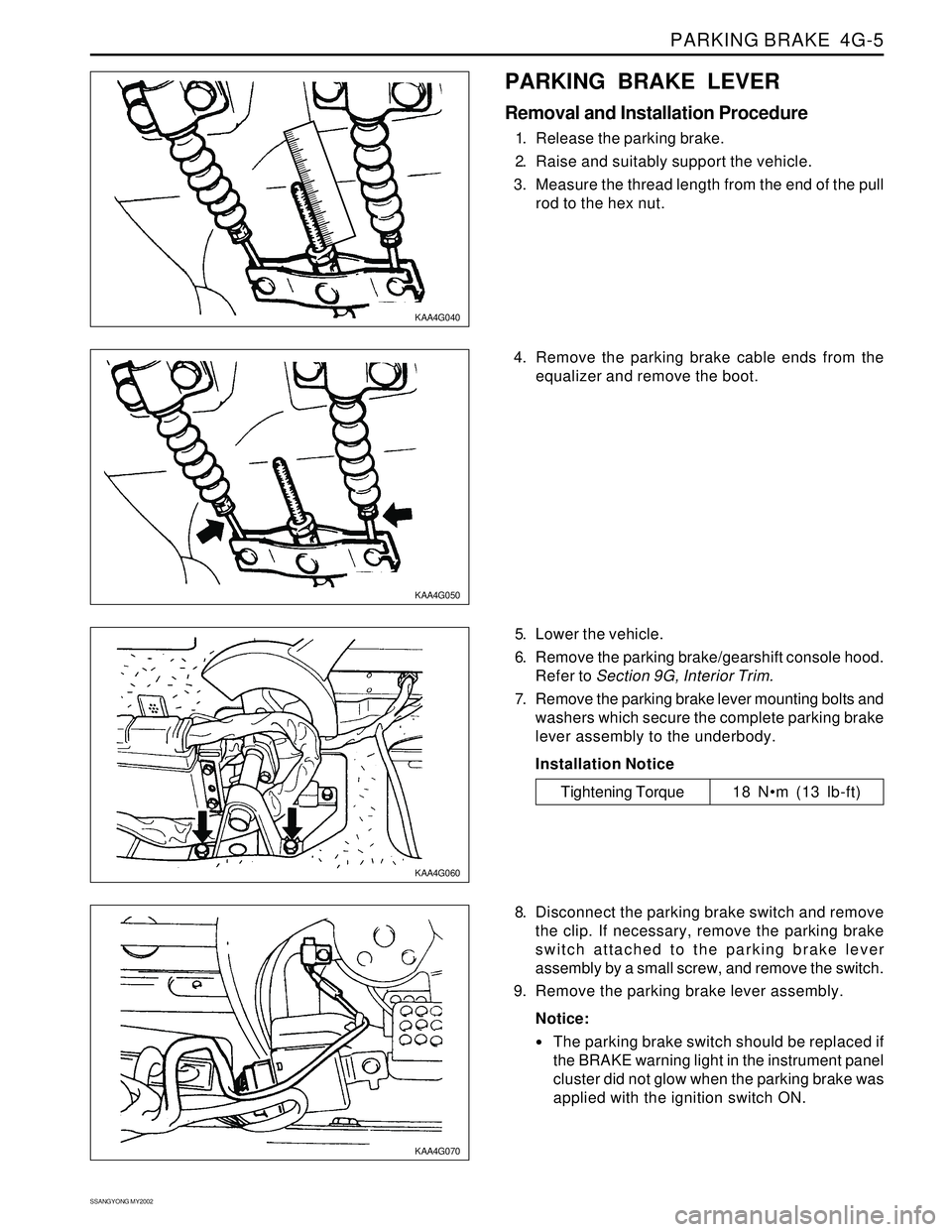
PARKING BRAKE LEVER
Removal and Installation Procedure
1. Release the parking brake.
2. Raise and suitably support the vehicle.
3. Measure the thread length from the end of the pull
rod to the hex nut.
5. Lower the vehicle.
6. Remove the parking brake/gearshift console hood.
Refer to Section 9G, Interior Trim.
7. Remove the parking brake lever mounting bolts and
washers which secure the complete parking brake
lever assembly to the underbody.
Installation Notice
8. Disconnect the parking brake switch and remove
the clip. If necessary, remove the parking brake
switch attached to the parking brake lever
assembly by a small screw, and remove the switch.
9. Remove the parking brake lever assembly.
Notice:
The parking brake switch should be replaced if
the BRAKE warning light in the instrument panel
cluster did not glow when the parking brake was
applied with the ignition switch ON.
Tightening Torque 18 Nm (13 lb-ft) 4. Remove the parking brake cable ends from the
equalizer and remove the boot.