coolant reservoir SSANGYONG KORANDO 1997 Service Repair Manual
[x] Cancel search | Manufacturer: SSANGYONG, Model Year: 1997, Model line: KORANDO, Model: SSANGYONG KORANDO 1997Pages: 2053, PDF Size: 88.33 MB
Page 13 of 2053

GENERAL INFORMATION 0B -- 13
D AEW OO M Y_2000
OWNER INSPECTIONS AND SERVICES
WHILE OPERATING THE VEHICLE
Horn Operation
Blow the horn occasionally to make sure it works. Check
all the button locations.
Brake System Operation
Be alert for abnormal sounds, increased brake pedal
travel or repeated puling to one side when braking. Also,
if the brake warning light goes on, or flashes, something
may be wrong with part of the brake system.
Exhaust System Operation
Be alert to any changes inthe sound of the system or
the smell of the fumes. These are signs that the system
may be leaking or overheating. Have the system in-
spected and repaired immediately.
Tires, Wheels and Alignment Operation
Be alert to any vibration of the steering wheel or the
seats at normal highway speeds. This may mean a
wheel needs to be balanced. Also, a pull right or left on a
straight, level road may show the need for a tire pres-
sure adjustment or a wheel alignment.
Steering System Operation
Be alert to changes in the steering action. An inspection
is needed when the steering wheel is hard to turn or has
too much free play, or is unusual sounds are noticed
when turning or parking.
Headlight Aim
Take note of the light pattern occasionally. Adjust the
headlights if the beams seem improperly aimed.
AT EACH FUEL FILL
A fluid loss in any (except windshield washer) system
may indicate a problem. Have the system inspected and
repaired immediately.
Engine Oil Level
Check the oil level and add oil if necessary. The best
time to check the engine oil level is when the oil is warm.
1. After stopping the engine, wait a few minutes for the
oil to drain back to the oil pan.
2. Pull out the oil level indicator (dip stick).
3. Wipe it clean, and push the oil level indicator back
down all the way.
4. Pull out the oil level indicator and look at the oil level
on it.
5. Add oil, if needed, to keep the oil level above the low-
er mark. Avoid overfilling theengine, since this may
cause engine damage.
6. Push the indicator all the way back down into the en-
gine after taking the reading.If you check the oil level when the oil is cold, do not run
the engine first. The cold oil will not drain back to the pan
fast enough to give a true oil level reading.
Engine Coolant Level and Condition
Check the coolant level in the coolant reservoir tank and
add coolant if necessary. Inspect the coolant. Replace
dirty or rusty coolant.
Windshield Washer Fluid Level
Check the washer fluid level in the reservoir. Add fluid if
necessary.
AT LEAST TWICE A MONTH
Tire And Wheel Inspection and Pressure
Check
Check the tire for abnormal wear or damage. Also check
for damaged wheels. Check the tire pressure when the
tires are cold ( check the spare also, unless it is a stow-
away). Maintain the recommended pressures. Refer to
“Tire and Wheel” is in section 0B.
AT LEAST MONTHLY
Light Operation
Check the operation of the license plate light, the head-
lights (including the high beams), the parking lights, the
fog lights, the taillight, the brake lights, the turn signals,
the backup lights and the hazard warning flasher.
Fluid Leak Check
Periodically inspect the surface beneath the vehicle for
water, oil, fuel or other fluids, after the vehicle has been
parked for a while. Water dripping from the air condition-
ing system after use is normal. If you notice fuel leaks or
fumes, find the cause and correct it at once.
AT LEAST TWICE A YEAR
Power Steering System Reservoir Level
Check the power steering fluid level. Keep the power
steering fluid at the proper level. Refer to Section 6A,
Power Steering System.
Brake Master Cylinder Reservoir Level
Check the fluid and keep it at the proper level. A low fluid
level can indicate worn disc brake pads which may need
to be serviced. Check the breather hole in the reservoir
cover to be free from dirt and check for an open pas-
sage.
Weather- Strip Lubrication
Apply a thin film silicone grease using a clean cloth.
Page 40 of 2053

1B1 -- 8 M162 ENGINE MECHANICAL
D AEW OO M Y_2000
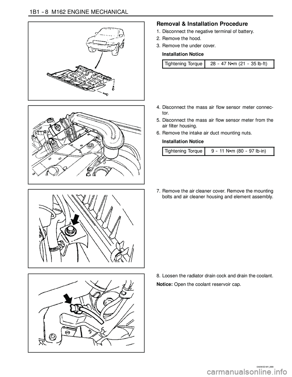
Removal & Installation Procedure
1. Disconnect the negative terminal of battery.
2. Remove the hood.
3. Remove the under cover.
Installation Notice
Tightening Torque
28 -- 47 NSm (21 -- 35 lb-ft)
4. Disconnect the mass air flow sensor meter connec-
tor.
5. Disconnect the mass air flow sensor meter from the
air filter housing.
6. Remove the intake air duct mounting nuts.
Installation Notice
Tightening Torque
9--11NSm (80 -- 97 lb-in)
7. Remove the air cleaner cover. Remove the mounting
bolts and air cleaner housing and element assembly.
8. Loosen the radiator drain cock and drain the coolant.
Notice:Open the coolant reservoir cap.
Page 138 of 2053

1D1 -- 2 M162 ENGINE COOLING
D AEW OO M Y_2000
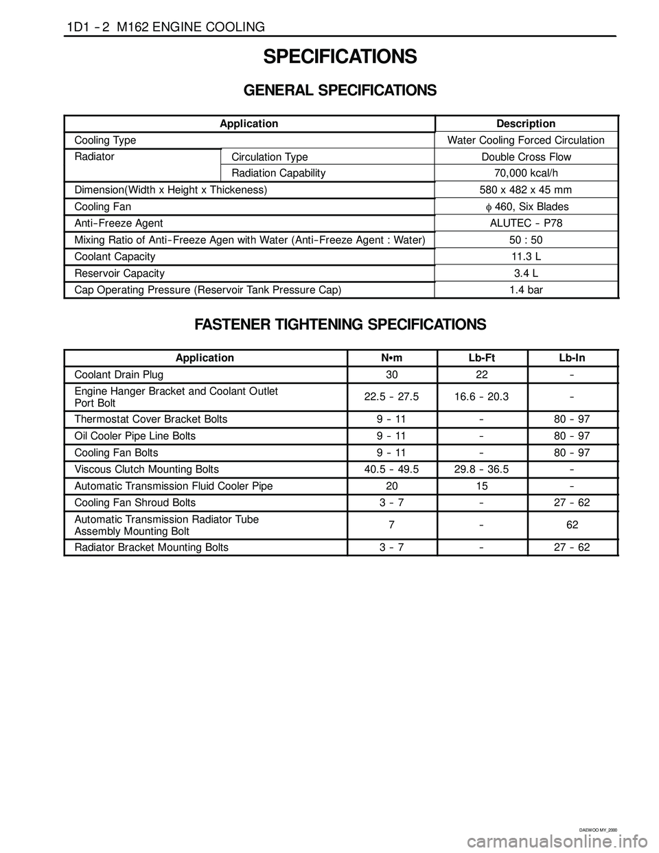
SPECIFICATIONS
GENERAL SPECIFICATIONS
ApplicationDescription
Cooling TypeWater Cooling Forced Circulation
RadiatorCirculation TypeDouble Cross Flow
Radiation Capability70,000 kcal/h
Dimension(Width x Height x Thickeness)580 x 482 x 45 mm
Cooling Fanφ460, Six Blades
Anti-- Freeze AgentALUTEC -- P78
Mixing Ratio of Anti-- Freeze Agen with Water (Anti-- Freeze Agent : Water)50 : 50
Coolant Capacity11. 3 L
Reservoir Capacity3.4 L
Cap Operating Pressure (Reservoir Tank Pressure Cap)1.4 bar
FASTENER TIGHTENING SPECIFICATIONS
ApplicationNSmLb-FtLb-In
Coolant Drain Plug3022--
Engine Hanger Bracket and Coolant Outlet
Port Bolt22.5 -- 27.516.6 -- 20.3--
Thermostat Cover Bracket Bolts9--11--80 -- 97
Oil Cooler Pipe Line Bolts9--11--80 -- 97
Cooling Fan Bolts9--11--80 -- 97
Viscous Clutch Mounting Bolts40.5 -- 49.529.8 -- 36.5--
Automatic Transmission Fluid Cooler Pipe2015--
Cooling Fan Shroud Bolts3--7--27 -- 62
Automatic Transmission Radiator Tube
Assembly Mounting Bolt7--62
Radiator Bracket Mounting Bolts3--7--27 -- 62
Page 140 of 2053

1D1 -- 4 M162 ENGINE COOLING
D AEW OO M Y_2000
DIAGNOSIS
SYSTEM LEAKAGE TEST
Tools Required
124 589 15 21 00 Tester
Test Procedure
1. Loosen the cap a little and release pressure and re-
move the cap.
Notice:For the risk of scalding, cap must not be opened
unless the coolant temperature is below 90°C.
2. Fill coolant up to upper edge (arrow) of reservoir.
3. Connect the special tool to the reservoir filler cap and
apply 1.4 bar of pressure.
Tester 124 589 15 21 00
4. If the pressure on the tester drops, check leakage at
the all coolant hoses and pipes and each connec-
tions. Replace or retighten if necessary.
Page 142 of 2053

1D1 -- 6 M162 ENGINE COOLING
D AEW OO M Y_2000
6. Remove the de-- aeration hose clamp in the coolant
pump and remove the de-- aeration hose.
7. Fill up the coolant through the coolant reservoir
tank.
Notice
DMatchtheanti--freezeandthewaterratioto50:50.
DSupplement the coolant until the coolant overflows to
the deaeration hose.
8. Insert the de--aeration hose and completely tighten
the clamp.
9. Check the coolant level in the coolant reservoir tank.
10. Warm up(until thermostat is opened) the engine and
recheck the coolant level in the reservoir tank and fill
up the coolant if necessary.
Page 301 of 2053

1B2 -- 8 M161 ENGINE MECHANICAL
D AEW OO M Y_2000
Removal & Installation Procedure
1. Disconnect the negative terminal of battery.
2. Remove the hood.
3. Remove the under cover.
Installation Notice
Tightening Torque
28 -- 47 NSm (21 -- 35 lb-ft)
4. Disconnect the coupling of HFM sensor and remove
the air cleaner cross pipe.
5. Remove the air cleaner cover. Remove the mounting
bolts and air cleaner housing and element assembly.
6. Loosen the radiator drain cock and drain the coolant.
Notice:Open the coolant reservoir cap.
Page 397 of 2053

1D2 -- 2 M161 ENGINE COOLING
D AEW OO M Y_2000
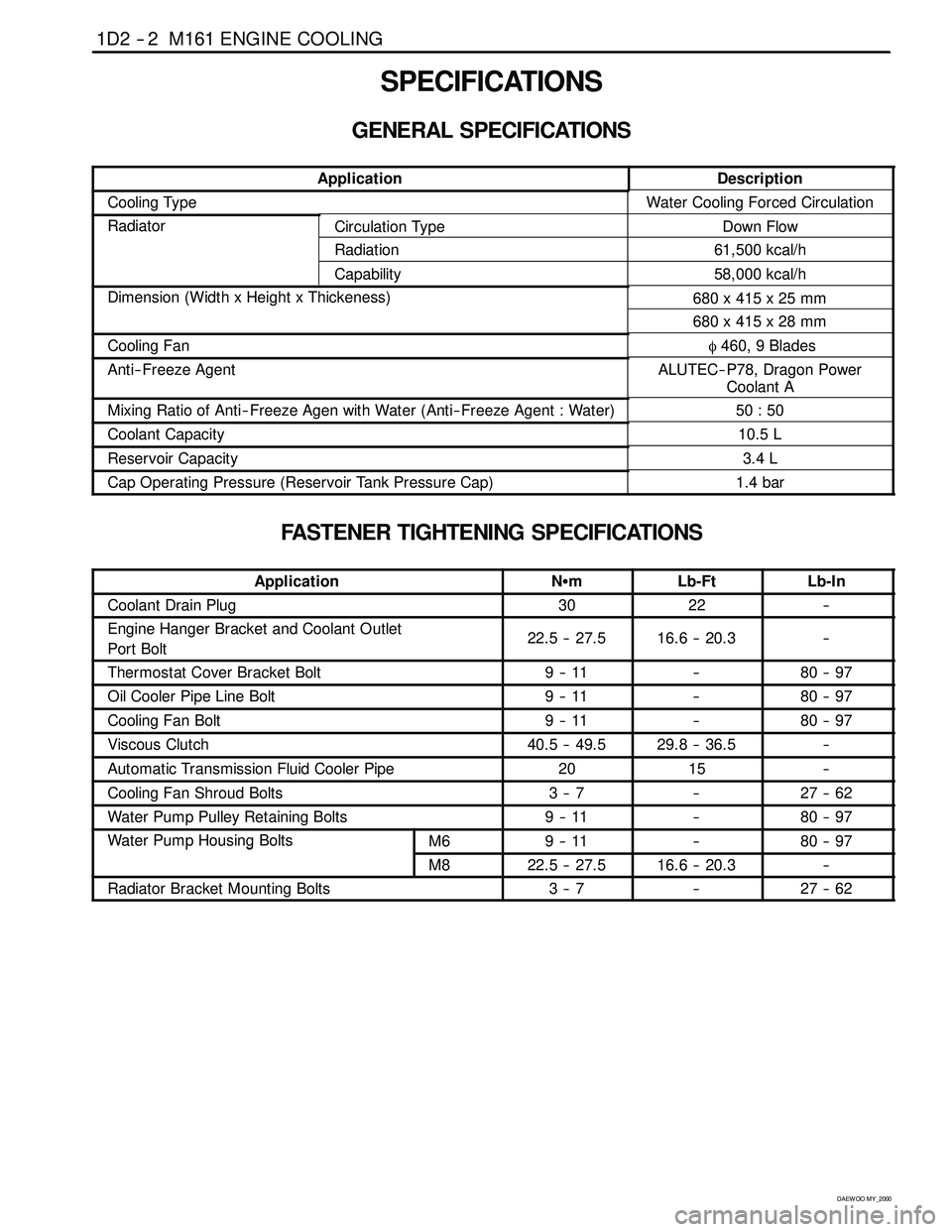
SPECIFICATIONS
GENERAL SPECIFICATIONS
ApplicationDescription
Cooling TypeWater Cooling Forced Circulation
RadiatorCirculation TypeDown Flow
Radiation61,500 kcal/h
Capability58,000 kcal/h
Dimension (Width x Height x Thickeness)680 x 415 x 25 mm(g)
680 x 415 x 28 mm
Cooling Fanφ460, 9 Blades
Anti-- Freeze AgentALUTEC-- P78, Dragon Power
Coolant A
Mixing Ratio of Anti-- Freeze Agen with Water (Anti-- Freeze Agent : Water)50 : 50
Coolant Capacity10.5 L
Reservoir Capacity3.4 L
Cap Operating Pressure (Reservoir Tank Pressure Cap)1.4 bar
FASTENER TIGHTENING SPECIFICATIONS
ApplicationNSmLb-FtLb-In
Coolant Drain Plug3022--
Engine Hanger Bracket and Coolant Outlet
Port Bolt22.5 -- 27.516.6 -- 20.3--
Thermostat Cover Bracket Bolt9--11--80 -- 97
Oil Cooler Pipe Line Bolt9--11--80 -- 97
Cooling Fan Bolt9--11--80 -- 97
Viscous Clutch40.5 -- 49.529.8 -- 36.5--
Automatic Transmission Fluid Cooler Pipe2015--
Cooling Fan Shroud Bolts3--7--27 -- 62
Water Pump Pulley Retaining Bolts9--11--80 -- 97
Water Pump Housing BoltsM69--11--80 -- 97pg
M822.5 -- 27.516.6 -- 20.3--
Radiator Bracket Mounting Bolts3--7--27 -- 62
Page 399 of 2053

1D2 -- 4 M161 ENGINE COOLING
D AEW OO M Y_2000
DIAGNOSIS
SYSTEM LEAKAGE TEST
Tools Required
124 589 15 21 00 Tester
Test Procedure
1. Loosen the cap a little and release pressure and re-
move the cap.
Notice:For the risk of scalding, cap must not be opened
unless the coolant temperature is below 90°C.
2. Fill coolant up to upper edge (arrow) of reservoir.
3. Connect the special tool to the reservoir filler cap and
apply 1.4 bar of pressure.
Tester 124 589 15 21 00
4. If the pressure on the tester drops, check leakage at
the all coolant hoses and pipes and each connec-
tions. Replace or retighten if necessary.
Page 401 of 2053

1D2 -- 6 M161 ENGINE COOLING
D AEW OO M Y_2000
4. After complete draining of the coolant, remove the
hose connector to drain plug and reinstall the drain
plug.
Installation Notice
Tightening Torque
30 NSm (22 lb-ft)
5. Tighten the radiator lower drain cock.
6. Remove the de-- aeration hose clamp in the water
pump and remove the de-- aeration hose.
7. Fill up the coolant through the coolant reservoir
tank.
Notice
DMatchtheanti--freezeandthewaterratioto50:50.
DSupplement the coolant until the coolant overflows to
the deaeration hose.
8. Insert the de--aeration hose and completely tighten
the clamp.
9. Check the coolant level in the coolant reservoir tank.
10. Warm up(until thermostat is opened) the engine and
recheck the coolant level in the reservoir tank and fill
up the coolant if necessary.
Page 410 of 2053

M161 ENGINE COOLING 1D2 -- 15
D AEW OO M Y_2000
REMOVAL AND INSTALLATION OF RADIATOR
Preceding Work: Removal of cooling fan shroud
1 Inlet Hose
2 Hose (to Engine)
3 Hose (to 3-- way Connector)
4 Make-- up Hose (to Coolant Reservoir)
5 3-- way Connector
6 Automatic Transmission Oil Cooling Hose
(A/T Equippend Vehicle)7 Bolt (M6 X 20, 4 pieces)
3--7 NSm (27-- 62 lb-in) .....................
8 Insulator
9 Radiator Bracket
10 Radiator