fuel cap SSANGYONG KORANDO 1997 Service Repair Manual
[x] Cancel search | Manufacturer: SSANGYONG, Model Year: 1997, Model line: KORANDO, Model: SSANGYONG KORANDO 1997Pages: 2053, PDF Size: 88.33 MB
Page 4 of 2053
0B -- 4 GENERAL INFORMATION
D AEW OO M Y_2000
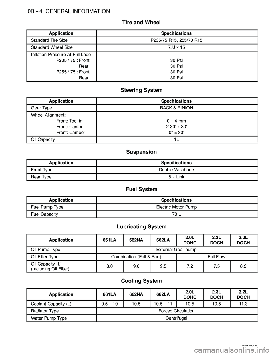
Tire and Wheel
ApplicationSpecifications
Standard Tire SizeP235/75 R15, 255/70 R15
Standard Wheel Size7JJx15
Inflation Pressure At Full Lode
P235 / 75 : Front
Rear
P255 / 75 : Front
Rear
30 Psi
30 Psi
30 Psi
30 Psi
Steering System
ApplicationSpecifications
Gear TypeRACK & PINION
Wheel Alignment:
Front: Toe -- in
Front: Caster
Front: Camber
0--4mm
2°30′±30′
0°±30′
Oil Capacity1L
Suspension
ApplicationSpecifications
Front TypeDouble Wishbone
Rear Type5--Link
Fuel System
ApplicationSpecifications
Fuel Pump TypeElectric Motor Pump
Fuel Capacity70 L
Lubricating System
Application661LA662NA662LA2.0L
DOHC2.3L
DOCH3.2L
DOCH
Oil Pump TypeExternal Gear pump
Oil Filter TypeCombination (Full & Part)Full Flow
Oil Capacity (L)
(Including Oil Filter)8.09.09.57.27.58.2
Cooling System
Application661LA662NA662LA2.0L
DOHC2.3L
DOCH3.2L
DOCH
Coolant Capacity (L)9.5 -- 1010.510.5 -- 1110.510.511. 3
Radiator TypeForced Circulation
Water Pump TypeCentrifugal
Page 14 of 2053
0B -- 14 GENERAL INFORMATION
D AEW OO M Y_2000
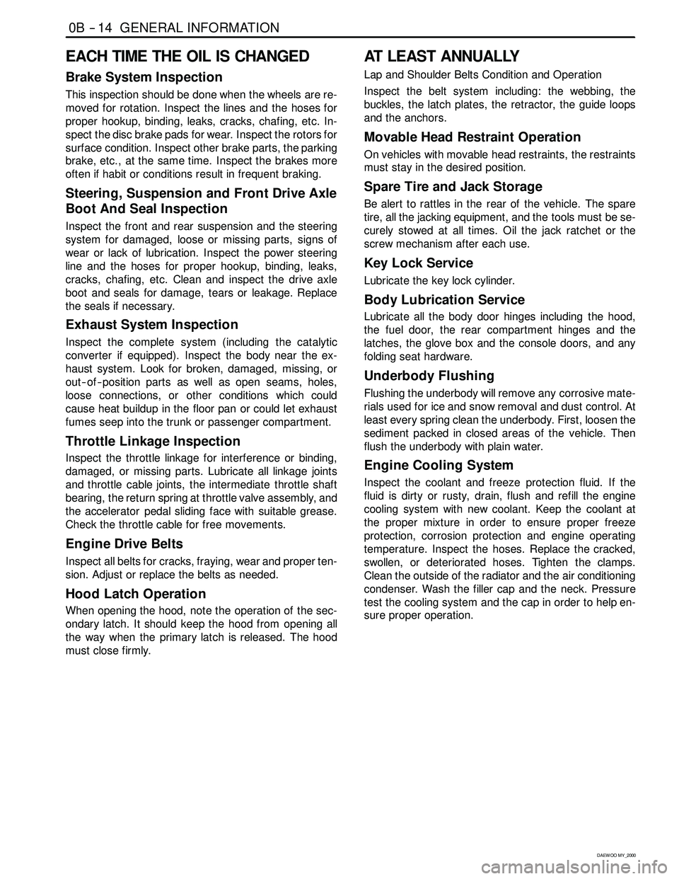
EACH TIME THE OIL IS CHANGED
Brake System Inspection
This inspection should be done when the wheels are re-
moved for rotation. Inspect the lines and the hoses for
proper hookup, binding, leaks, cracks, chafing, etc. In-
spect the disc brake pads for wear. Inspect the rotors for
surface condition. Inspect other brake parts, the parking
brake, etc., at the same time. Inspect the brakes more
often if habit or conditions result in frequent braking.
Steering, Suspension and Front Drive Axle
Boot And Seal Inspection
Inspect the front and rear suspension and the steering
system for damaged, loose or missing parts, signs of
wear or lack of lubrication. Inspect the power steering
line and the hoses for proper hookup, binding, leaks,
cracks, chafing, etc. Clean and inspect the drive axle
boot and seals for damage, tears or leakage. Replace
the seals if necessary.
Exhaust System Inspection
Inspect the complete system (including the catalytic
converter if equipped). Inspect the body near the ex-
haust system. Look for broken, damaged, missing, or
out -- of -- position parts as well as open seams, holes,
loose connections, or other conditions which could
cause heat buildup in the floor pan or could let exhaust
fumes seep into the trunk or passenger compartment.
Throttle Linkage Inspection
Inspect the throttle linkage for interference or binding,
damaged, or missing parts. Lubricate all linkage joints
and throttle cable joints, the intermediate throttle shaft
bearing, the return spring at throttle valve assembly, and
the accelerator pedal sliding face with suitable grease.
Check the throttle cable for free movements.
Engine Drive Belts
Inspect all belts for cracks, fraying, wear and proper ten-
sion. Adjust or replace the belts as needed.
Hood Latch Operation
When opening the hood, note the operation of the sec-
ondary latch. It should keep the hood from opening all
the way when the primary latch is released. The hood
must close firmly.
AT LEAST ANNUALLY
Lap and Shoulder Belts Condition and Operation
Inspect the belt system including: the webbing, the
buckles, the latch plates, the retractor, the guide loops
and the anchors.
Movable Head Restraint Operation
On vehicles with movable head restraints, the restraints
must stay in the desired position.
Spare Tire and Jack Storage
Be alert to rattles in the rear of the vehicle. The spare
tire, all the jacking equipment, and the tools must be se-
curely stowed at all times. Oil the jack ratchet or the
screw mechanism after each use.
Key Lock Service
Lubricate the key lock cylinder.
Body Lubrication Service
Lubricate all the body door hinges including the hood,
the fuel door, the rear compartment hinges and the
latches, the glove box and the console doors, and any
folding seat hardware.
Underbody Flushing
Flushing the underbody will remove any corrosive mate-
rials used for ice and snow removal and dust control. At
least every spring clean the underbody. First, loosen the
sediment packed in closed areas of the vehicle. Then
flush the underbody with plain water.
Engine Cooling System
Inspect the coolant and freeze protection fluid. If the
fluid is dirty or rusty, drain, flush and refill the engine
cooling system with new coolant. Keep the coolant at
the proper mixture in order to ensure proper freeze
protection, corrosion protection and engine operating
temperature. Inspect the hoses. Replace the cracked,
swollen, or deteriorated hoses. Tighten the clamps.
Clean the outside of the radiator and the air conditioning
condenser. Wash the filler cap and the neck. Pressure
test the cooling system and the cap in order to help en-
sure proper operation.
Page 15 of 2053
GENERAL INFORMATION 0B -- 15
D AEW OO M Y_2000
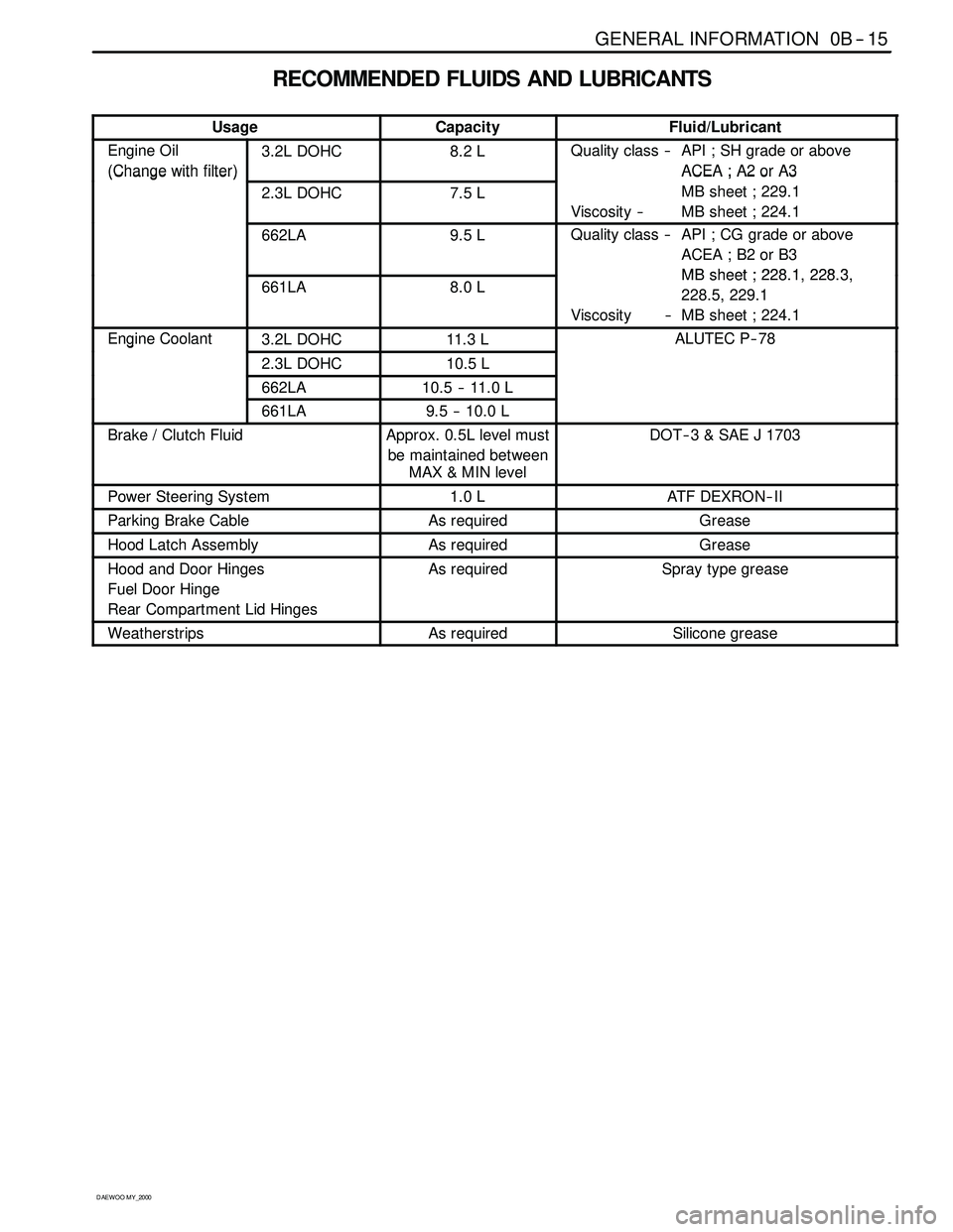
RECOMMENDED FLUIDS AND LUBRICANTS
UsageCapacityFluid/Lubricant
Engine Oil
(Change with filter)3.2L DOHC8.2 LQuality class -- API ; SH grade or above
ACEA ; A2 or A3
(Changewithfilter)
2.3L DOHC7.5 L
ACEA;A2orA3
MB sheet ; 229.1
Viscosity -- MB sheet ; 224.1
662LA9.5 LQuality class -- API ; CG grade or above
ACEA ; B2 or B3
MBsheet;22812283661LA8.0 LMBsheet ; 228.1, 228.3,
228.5, 229.1
Viscosity -- MB sheet ; 224.1
Engine Coolant3.2L DOHC11. 3 LALUTEC P-- 78g
2.3L DOHC10.5 L
662LA10.5 -- 11.0 L
661LA9.5 -- 10.0 L
Brake / Clutch FluidApprox. 0.5L level must
be maintained between
MAX&MINlevelDOT -- 3 & SAE J 1703
Power Steering System1.0 LATF DEXRON--II
Parking Brake CableAs requiredGrease
Hood Latch AssemblyAs requiredGrease
Hood and Door Hinges
Fuel Door Hinge
Rear Compartment Lid HingesAs requiredSpray type grease
WeatherstripsAs requiredSilicone grease
Page 22 of 2053
1A1 -- 2 GENERAL ENGINE INFORMATION
D AEW OO M Y_2000
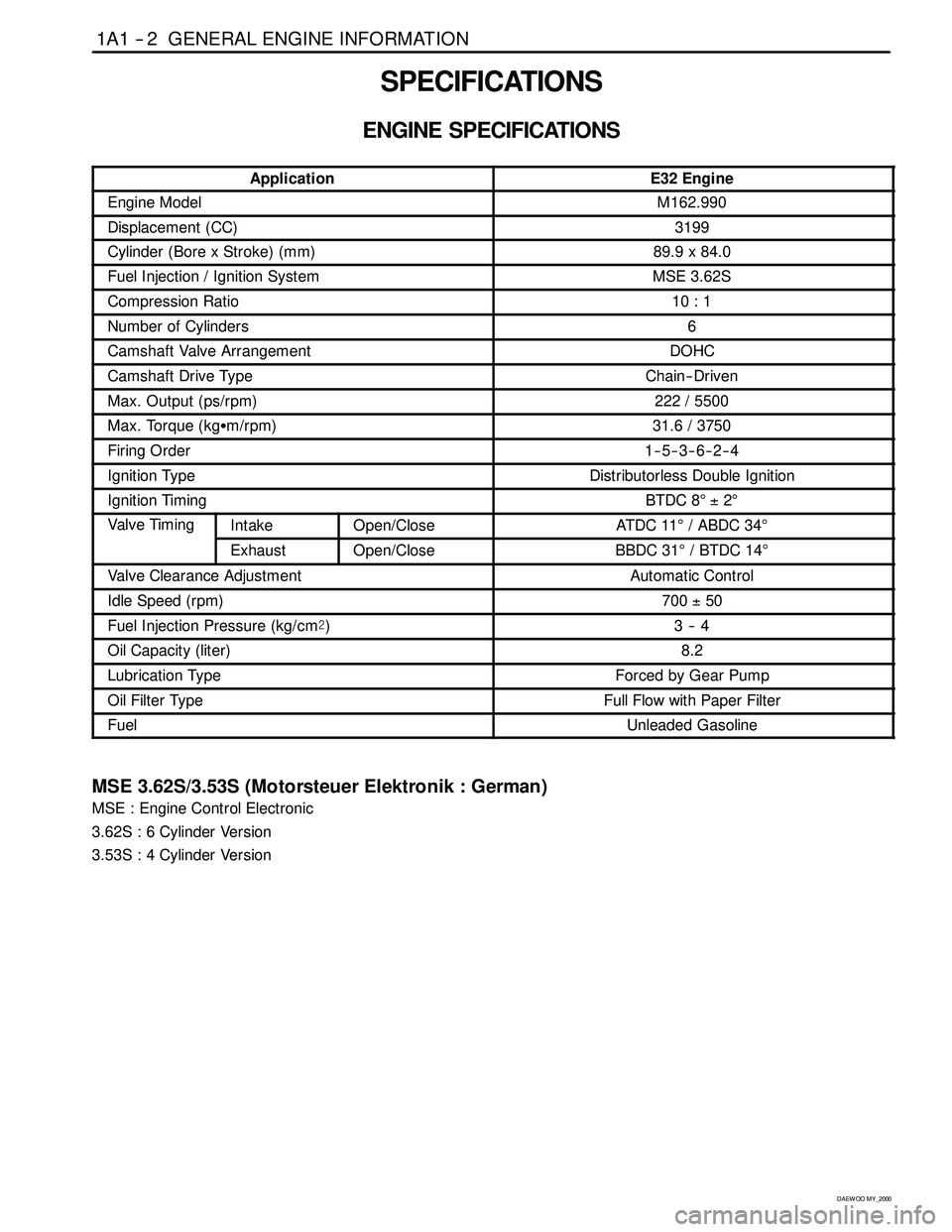
SPECIFICATIONS
ENGINE SPECIFICATIONS
ApplicationE32 Engine
Engine ModelM162.990
Displacement (CC)3199
Cylinder (Bore x Stroke)(mm)89.9 x 84.0
Fuel Injection / Ignition SystemMSE 3.62S
Compression Ratio10 : 1
Number of Cylinders6
Camshaft Valve ArrangementDOHC
Camshaft Drive TypeChain-- Driven
Max. Output (ps/rpm)222 / 5500
Max. Torque (kgSm/rpm)31.6 / 3750
Firing Order1--5--3--6--2--4
Ignition TypeDistributorless Double Ignition
Ignition TimingBTDC 8°±2°
Valve TimingIntakeOpen/CloseAT DC 11°/ ABDC 34°g
ExhaustOpen/CloseBBDC 31°/BTDC14°
Valve Clearance AdjustmentAutomatic Control
Idle Speed (rpm)700±50
Fuel Injection Pressure (kg/cm@)3--4
Oil Capacity (liter)8.2
Lubrication TypeForced by Gear Pump
Oil Filter TypeFull Flow with Paper Filter
FuelUnleaded Gasoline
MSE 3.62S/3.53S (Motorsteuer Elektronik : German)
MSE : Engine Control Electronic
3.62S : 6 Cylinder Version
3.53S : 4 Cylinder Version
Page 34 of 2053
1B1 -- 2 M162 ENGINE MECHANICAL
D AEW OO M Y_2000
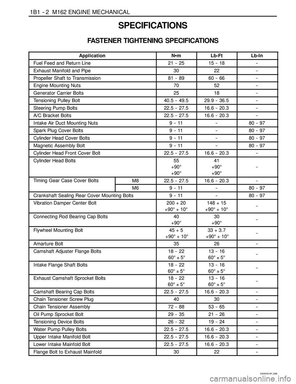
SPECIFICATIONS
FASTENER TIGHTENING SPECIFICATIONS
ApplicationNSmLb-FtLb-In
Fuel Feed and Return Line21 -- 2515 -- 18--
Exhaust Manifold and Pipe3022--
Propeller Shaft to Transmission81 -- 8960 -- 66--
Engine Mounting Nuts7052--
Generator Carrier Bolts2518--
Tensioning Pulley Bolt40.5 -- 49.529.9 -- 36.5--
Steering Pump Bolts22.5 -- 27.516.6 -- 20.3--
A/C Bracket Bolts22.5 -- 27.516.6 -- 20.3--
Intake Air Duct Mounting Nuts9--11--80 -- 97
Spark Plug Cover Bolts9--11--80 -- 97
Cylinder Head Cover Bolts9--11--80 -- 97
Magnetic Assembly Bolt9--11--80 -- 97
Cylinder Head Front Cover Bolt22.5 -- 27.516.6 -- 20.3--
Cylinder Head Bolts55
+90°
+90°41
+90°
+90°
--
Timing Gear Case Cover BoltsM822.5 -- 27.516.6 -- 20.3--g
M69--11--80 -- 97
Crankshaft Sealing Rear Cover Mounting Bolts9--11--80 -- 97
Vibration Damper Center Bolt200 + 20
+90°+10°148 + 15
+90°+10°--
Connecting Rod Bearing Cap Bolts40
+90°30
+90°--
Flywheel Mounting Bolt45 + 5
+90°+10°33 + 3.7
+90°+10°--
Amarture Bolt3526--
Camshaft Adjuster Flange Bolts18 -- 22
60°±5°13 -- 16
60°±5°--
Intake Flange Shaft Bolts18 -- 22
60°±5°13 -- 16
60°±5°--
Exhaust Camshaft Sprocket Bolts18 -- 22
60°±5°13 -- 16
60°±5°--
Camshaft Bearing Cap Bolts22.5 -- 27.516.6 -- 20.3--
Chain Tensioner Screw Plug4030--
Chain Tensioner Assembly72 -- 8853 -- 65--
Oil Pump Sprocket Bolt29 -- 3521 -- 26--
Tensioning Device Bolts26 -- 3219 -- 24--
Water Pump Pulley Bolts22.5 -- 27.516.6 -- 20.3--
Upper Intake Manifold Bolt22.5 -- 27.516.6 -- 20.3--
Lower Intake Mainfold Bolt22.5 -- 27.516.6 -- 20.3--
Flange Bolt to Exhaust Mainfold3022--
Page 169 of 2053

1F1 -- 6 M162 ENGINE CONTROLS
D AEW OO M Y_2000
SPECIAL TOOLS AND EQUIPMENT
SPECIAL TOOLS TABLE
YAA1F890
661 589 00 46 00
Fuel Tank Cap Wrench
KAA1F490
103 589 00 21 00
Fuel Pressure Gauge
Page 207 of 2053

1F1 -- 44 M162 ENGINE CONTROLS
D AEW OO M Y_2000
Measure the Fuel Delivery from the Fuel Pump
1. Disconnect the return pipe from fuel distributor and insert the appropriate hose into it.
2. Place the hose end into the beaker with the minimum capacity of 1 Liter
3. Turn the ignition switch to “ON” position.
4. Connect the terminal No. 33 and No. 5 of ECM with a service wire.
5. Measure the fuel delivery from the fuel pump
Specified Value
1 Liter/max. 35 sec.
Notice:Check the fuel filter and fuel line when the fuel delivery is not within specified value.
Measure the Current Consumption of Fuel Pump
1. Remove the fuel pump relay from fuse and relay box in trunk, and turn the ignition switch to “ON” position.
2. Using a multimeter, measure the current consumption by connecting the terminal No. 30 and No. 87 of the fuel
pump relay connector.
Specified Value
5~9A
Notice:Replace the fuel pump relay if the measured value is over 9 A.
Page 246 of 2053
M162 ENGINE CONTROLS 1F1 -- 83
D AEW OO M Y_2000
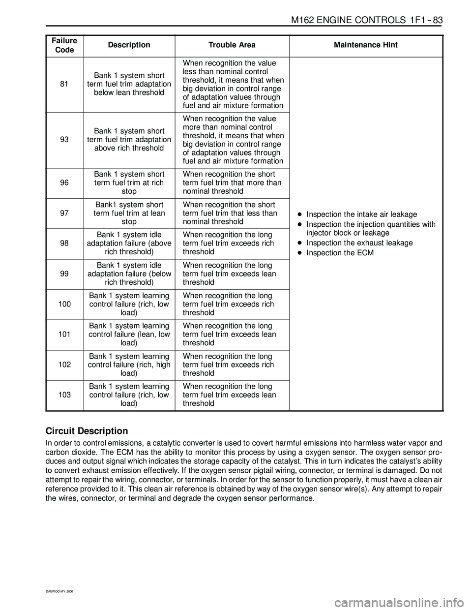
Failure
CodeDescriptionTrouble AreaMaintenance Hint
81
Bank 1 system short
term fuel trim adaptation
below lean threshold
When recognition the value
less than nominal control
threshold, it means that when
big deviation in control range
of adaptation values through
fuel and air mixture formation
93
Bank 1 system short
term fuel trim adaptation
above rich threshold
When recognition the value
more than nominal control
threshold, it means that when
big deviation in control range
of adaptation values through
fuel and air mixture formation
96
Bank 1 system short
term fuel trim at rich
stopWhen recognition the short
term fuel trim that more than
nominal threshold
97
Bank1 system short
term fuel trim at lean
stopWhen recognition the short
term fuel trim that less than
nominal threshold
DInspection the intake air leakage
DIns
pection the injectionquantities with
98
Bank 1 system idle
adaptation failure (above
rich threshold)When recognition the long
term fuel trim exceeds rich
threshold
DInspectiontheinjectionquantitieswith
injector block or leakage
DInspection the exhaust leakage
DInspection the ECM
99
Bank 1 system idle
adaptation failure (below
rich threshold)When recognition the long
term fuel trim exceeds lean
threshold
p
100
Bank 1 system learning
control failure (rich, low
load)When recognition the long
term fuel trim exceeds rich
threshold
101
Bank 1 system learning
control failure (lean, low
load)When recognition the long
term fuel trim exceeds lean
threshold
102
Bank 1 system learning
control failure (rich, high
load)When recognition the long
term fuel trim exceeds rich
threshold
103
Bank 1 system learning
control failure (rich, low
load)When recognition the long
term fuel trim exceeds lean
threshold
Circuit Description
In order to control emissions, a catalytic converter is used to covert harmful emissions into harmless water vapor and
carbon dioxide. The ECM has the ability to monitor this process by using a oxygen sensor. The oxygen sensor pro-
duces and output signal which indicates the storage capacity of the catalyst. This in turn indicates the catalyst’s ability
to convert exhaust emission effectively. If the oxygen sensor pigtail wiring, connector, or terminal is damaged. Do not
attempt to repair the wiring, connector, or terminals. In order for the sensor to function properly, it must have a clean air
reference provided to it. This clean air reference is obtained by way of the oxygen sensor wire(s). Any attempt to repair
the wires, connector, or terminal and degrade the oxygen sensor performance.
Page 258 of 2053
M162 ENGINE CONTROLS 1F1 -- 95
D AEW OO M Y_2000
MAINTENANCE AND REPAIR
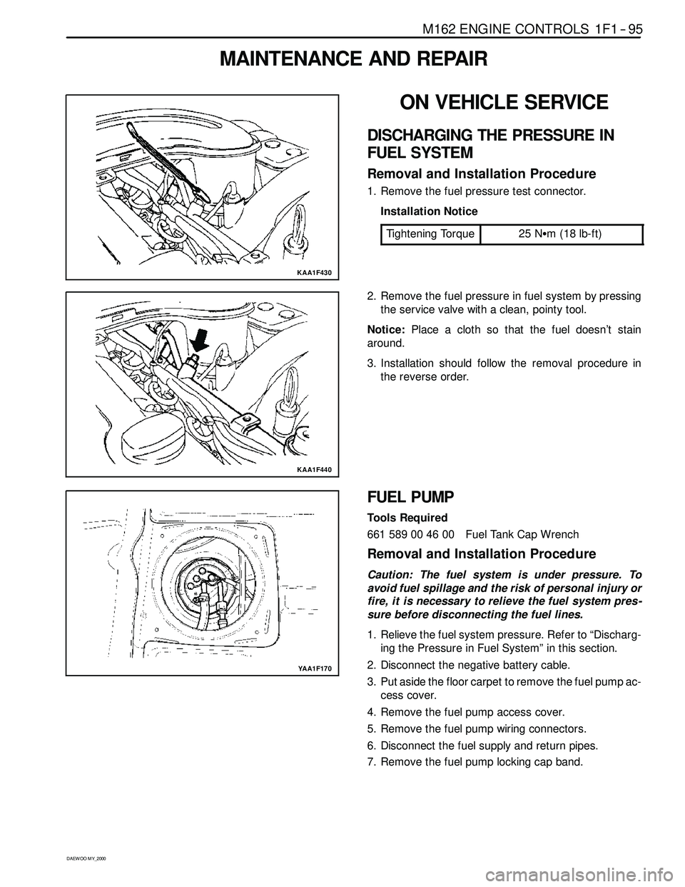
KAA1F430
ON VEHICLE SERVICE
DISCHARGING THE PRESSURE IN
FUEL SYSTEM
Removal and Installation Procedure
1. Remove the fuel pressure test connector.
Installation Notice
Tightening Torque
25 NSm (18 lb-ft)
KAA1F440
2. Remove the fuel pressure in fuel system by pressing
the service valve with a clean, pointy tool.
Notice:Place a cloth so that the fuel doesn’t stain
around.
3. Installation should follow the removal procedure in
the reverse order.
YAA1F170
FUEL PUMP
Tools Required
661 589 00 46 00 Fuel Tank Cap Wrench
Removal and Installation Procedure
Caution: The fuel system is under pressure. To
avoid fuel spillage and the risk of personal injury or
fire, it is necessary to relieve the fuel system pres -
sure before disconnecting the fuel lines.
1. Relieve the fuel system pressure. Refer to “Discharg-
ing the Pressure in Fuel System” in this section.
2. Disconnect the negative battery cable.
3. Put aside the floor carpet to remove the fuel pump ac-
cess cover.
4. Remove the fuel pump access cover.
5. Remove the fuel pump wiring connectors.
6. Disconnect the fuel supply and return pipes.
7. Remove the fuel pump locking cap band.
Page 259 of 2053
1F1 -- 96 M162 ENGINE CONTROLS
D AEW OO M Y_2000
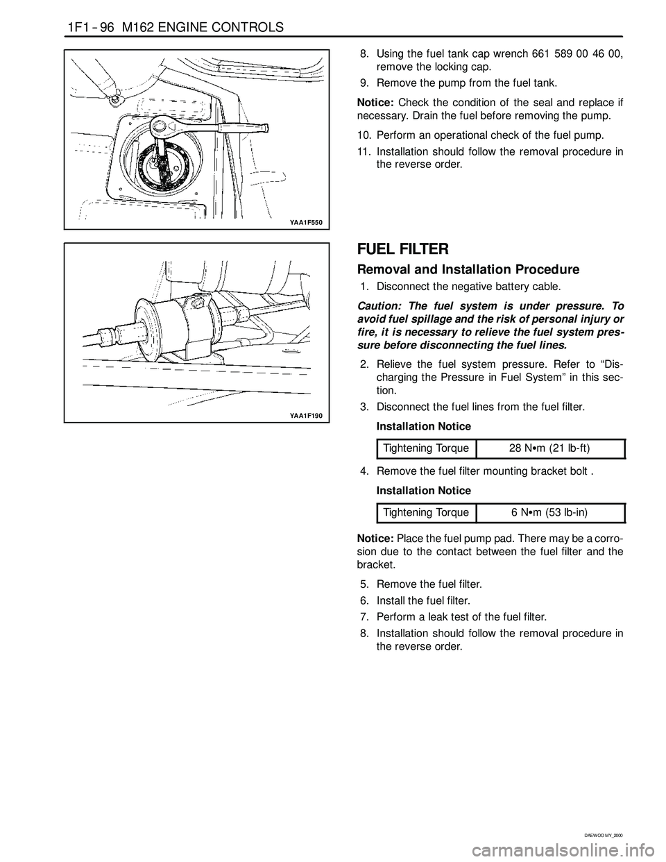
YAA1F550
8. Using the fuel tank cap wrench 661 589 00 46 00,
remove the locking cap.
9. Remove the pump from the fuel tank.
Notice:Check the condition of the seal and replace if
necessary. Drain the fuel before removing the pump.
10. Perform an operational check of the fuel pump.
11. Installation should follow the removal procedure in
the reverse order.
YAA1F190
FUEL FILTER
Removal and Installation Procedure
1. Disconnect the negative battery cable.
Caution: The fuel system is under pressure. To
avoid fuel spillage and the risk of personal injury or
fire, it is necessary to relieve the fuel system pres -
sure before disconnecting the fuel lines.
2. Relieve the fuel system pressure. Refer to “Dis-
charging the Pressure in Fuel System” in this sec-
tion.
3. Disconnect the fuel lines from the fuel filter.
Installation Notice
Tightening Torque
28 NSm (21 lb-ft)
4. Remove the fuel filter mounting bracket bolt .
Installation Notice
Tightening Torque
6NSm (53 lb-in)
Notice:Place the fuel pump pad. There may be a corro-
sion due to the contact between the fuel filter and the
bracket.
5. Remove the fuel filter.
6. Install the fuel filter.
7. Perform a leak test of the fuel filter.
8. Installation should follow the removal procedure in
the reverse order.