wheel torque SSANGYONG KORANDO 1997 Service Repair Manual
[x] Cancel search | Manufacturer: SSANGYONG, Model Year: 1997, Model line: KORANDO, Model: SSANGYONG KORANDO 1997Pages: 2053, PDF Size: 88.33 MB
Page 16 of 2053
0B -- 16 GENERAL INFORMATION
D AEW OO M Y_2000
GENERAL DESCRIPTION AND SYSTEM OPERATION
GENERAL REPAIR INSTRUCTIONS
DIf a floor jack is used, the following precautions are
recommended.
DPark the vehicle on level ground, “block” the front or
rear wheels, set the jack against the frame, raise the
vehicle and support it with chassis stands and then
perform the service operation.
DBefore performing the service operation, disconnect
the negative battery cable in order to reduce the
chance of cable damaged and burning due to short --
cir cuiting.
DUse a cover on the body, the seats and the floor to
protect them against damage and contamination.
DHandle brake fluid and antifreeze solution with care
as they can cause paint damage.
DThe use of proper tools, and the recommended es-
sential and available tools where specified, are impor-
tant for efficient and reliable performance of the
service repairs.
DUse genuine DAEWOO parts.DDiscard used cotter pins, gaskets, O -- rings, oil seals,
lock washers and self -- locking nuts. Prepare new
ones for installation. Normal function of these parts
cannot be maintained if these parts are reused.
DKeep the disassembled parts neatly in groups to facil-
itate proper and smooth reassembly.
DKeep attaching bolts and nuts separated, as they
vary in hardness and design depending on the posi-
tion of the installation.
DClean the parts before inspection or reassembly.
DAlso clean the oil parts, etc. Use compressed air to
make certain they are free of restrictions.
DLubricate rotating and sliding faces of parts with oil or
grease before installation.
DWhen necessary, use a sealer on gaskets to prevent
leakage.
DCarefully observe all specifications for bolt and nut
torques.
DWhen service operation is completed, make a final
check to be sure service was done properly and the
problem was corrected.
Page 69 of 2053
M162 ENGINE MECHANICAL 1B1 -- 37
D AEW OO M Y_2000
Tools Required
602589004000 EngineLock
Removal & Installation Procedure
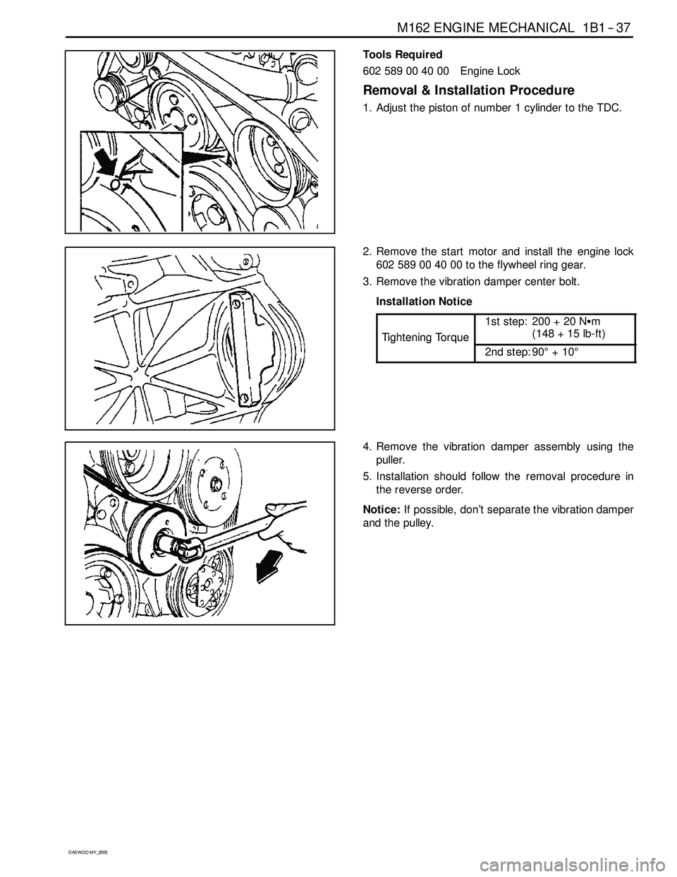
1. Adjust the piston of number 1 cylinder to the TDC.
2. Remove the start motor and install the engine lock
602 589 00 40 00 to the flywheel ring gear.
3. Remove the vibration damper center bolt.
Installation Notice
Ti
ghteningTo rque
1st step: 200 + 20 NSm
(148 + 15 lb-ft)
TighteningTorque
2nd step: 90°+10°
4. Remove the vibration damper assembly using the
puller.
5. Installation should follow the removal procedure in
the reverse order.
Notice:If possible, don’t separate the vibration damper
and the pulley.
Page 79 of 2053
M162 ENGINE MECHANICAL 1B1 -- 47
D AEW OO M Y_2000
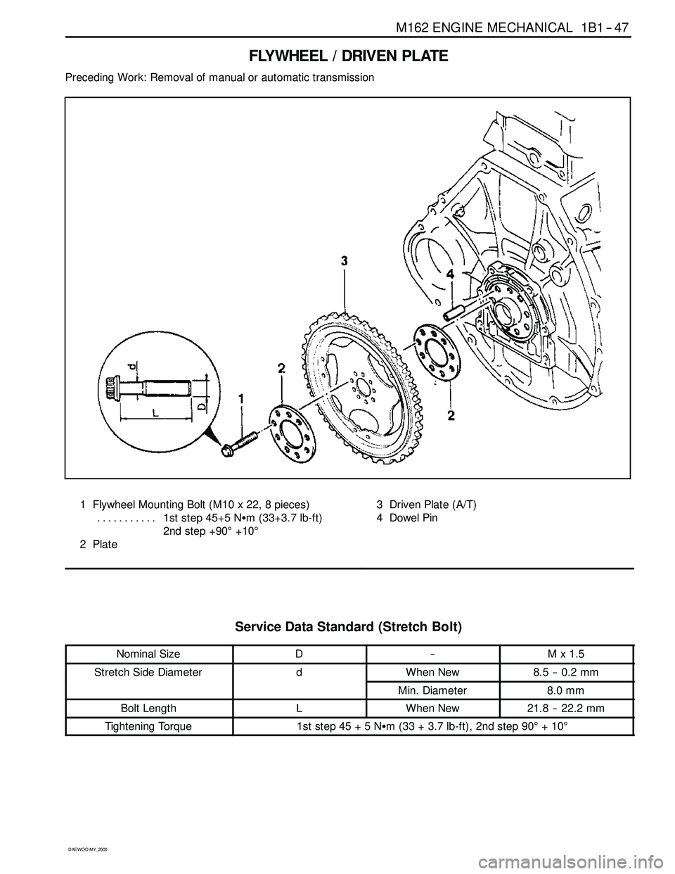
FLYWHEEL / DRIVEN PLATE
Preceding Work: Removal of manual or automatic transmission
1 Flywheel Mounting Bolt (M10 x 22, 8 pieces)
1st step 45+5 NSm (33+3.7 lb-ft) ...........
2nd step +90°+10°
2Plate3 Driven Plate (A/T)
4 Dowel Pin
Service Data Standard (Stretch Bolt)
Nominal SizeD--Mx1.5
Stretch Side DiameterdWhen New8.5 -- 0.2 mm
Min. Diameter8.0 mm
Bolt LengthLWhen New21.8 -- 22.2 mm
Tightening Torque1ststep45+5NSm (33 + 3.7 lb-ft), 2nd step 90°+10°
Page 80 of 2053
1B1 -- 48 M162 ENGINE MECHANICAL
D AEW OO M Y_2000
Removal & Installation Procedure
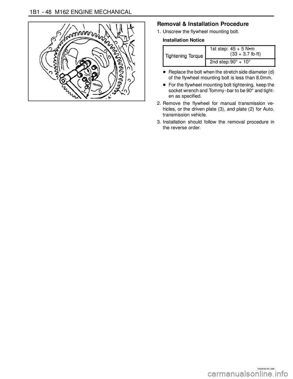
1. Unscrew the flywheel mounting bolt.
Installation Notice
Ti
ghteningTo rque
1st step: 45 + 5 NSm
(33+3.7lb-ft)
TighteningTorque
2nd step: 90°+10°
DReplace the bolt when the stretch side diameter (d)
of the flywheel mounting bolt is less than 8.0mm.
DFor the flywheel mounting bolt tightening, keep the
socket wrench and Tommy -- bar to be 90°and tight-
en as specified.
2. Remove the flywheel for manual transmission ve-
hicles, or the driven plate (3), and plate (2) for Auto.
transmission vehicle.
3. Installation should follow the removal procedure in
the reverse order.
Page 334 of 2053
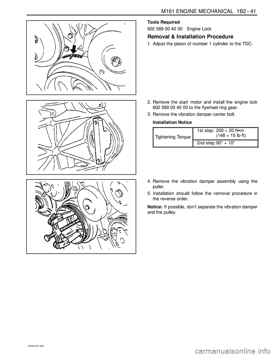
M161 ENGINE MECHANICAL 1B2 -- 41
D AEW OO M Y_2000
Tools Required
602589004000 EngineLock
Removal & Installation Procedure
1. Adjust the piston of number 1 cylinder to the TDC.
2. Remove the start motor and install the engine lock
602 589 00 40 00 to the flywheel ring gear.
3. Remove the vibration damper center bolt.
Installation Notice
Ti
ghteningTo rque
1st step: 200 + 20 NSm
(148 + 15 lb-ft)
TighteningTorque
2nd step: 90°+10°
4. Remove the vibration damper assembly using the
puller.
5. Installation should follow the removal procedure in
the reverse order.
Notice:If possible, don’t separate the vibration damper
and the pulley.
Page 344 of 2053
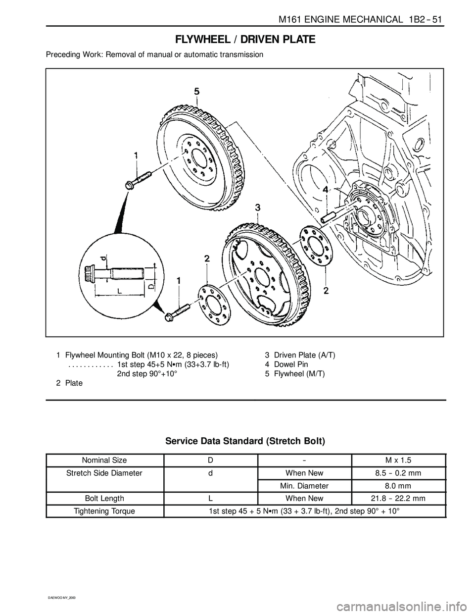
M161 ENGINE MECHANICAL 1B2 -- 51
D AEW OO M Y_2000
FLYWHEEL / DRIVEN PLATE
Preceding Work: Removal of manual or automatic transmission
1 Flywheel Mounting Bolt (M10 x 22, 8 pieces)
1st step 45+5 NSm (33+3.7 lb-ft) ............
2nd step 90°+10°
2Plate3 Driven Plate (A/T)
4 Dowel Pin
5 Flywheel (M/T)
Service Data Standard (Stretch Bolt)
Nominal SizeD--Mx1.5
Stretch Side DiameterdWhen New8.5 -- 0.2 mm
Min. Diameter8.0 mm
Bolt LengthLWhen New21.8 -- 22.2 mm
Tightening Torque1ststep45+5NSm (33 + 3.7 lb-ft), 2nd step 90°+10°
Page 345 of 2053
1B2 -- 52 M161 ENGINE MECHANICAL
D AEW OO M Y_2000
Removal & Installation Procedure
1. Unscrew the flywheel mounting bolt.
Installation Notice
Ti
ghteningTo rque
1st step: 45 + 5 NSm
(33+3.7lb-ft)
TighteningTorque
2nd step: 90°+10°
DReplace the bolt when the stretch side diameter (d)
of the flywheel mounting bolt is less than 8.0mm.
DFor the flywheel mounting bolt tightening, keep the
socket wrench and Tommy -- bar to be 90°and tight-
en as specified.
2. Remove the flywheel for manual transmission ve-
hicles, or the driven plate (3), and plate (2) for Auto.
transmission vehicle.
3. Installation should follow the removal procedure in
the reverse order.
Page 644 of 2053
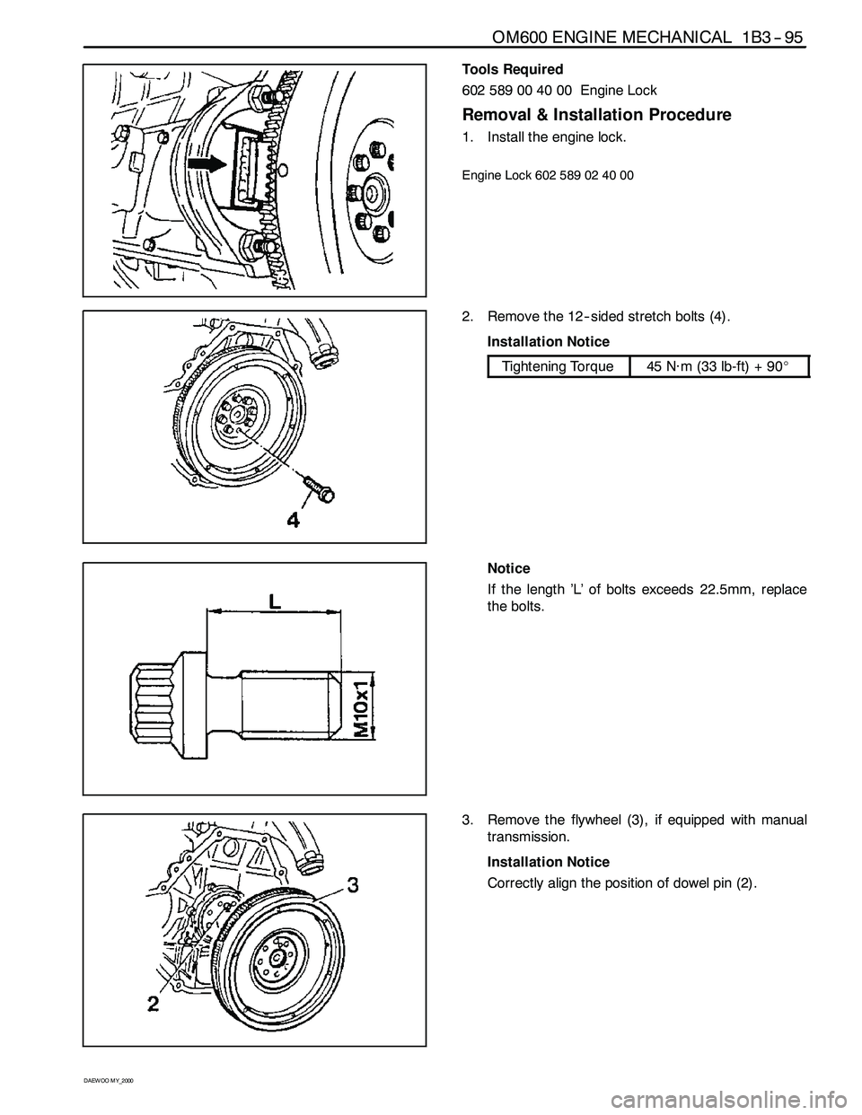
OM600 ENGINE MECHANICAL 1B3 -- 95
D AEW OO M Y_2000
Tools Required
602 589 00 40 00 Engine Lock
Removal & Installation Procedure
1. Install the engine lock.
Engine Lock 602 589 02 40 00
2. Remove the 12-- sided stretch bolts (4).
Installation Notice
Tightening Torque45 N∙m (33 lb-ft) + 90_
Notice
If the length ’L’ of bolts exceeds 22.5mm, replace
the bolts.
3. Remove the flywheel (3), if equipped with manual
transmission.
Installation Notice
Correctly align the position of dowel pin (2).
Page 826 of 2053
WHEEL ALIGNMENT 2B-7
SSANGYONG MY2002
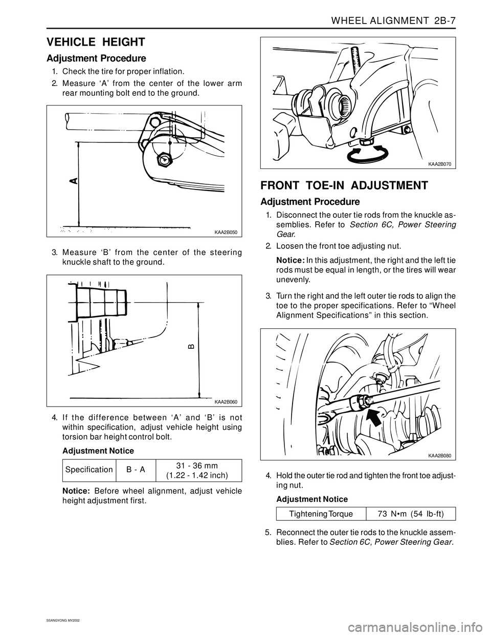
VEHICLE HEIGHT
Adjustment Procedure
1. Check the tire for proper inflation.
2. Measure ‘A’ from the center of the lower arm
rear mounting bolt end to the ground.
KAA2B050
3. Measure ‘B’ from the center of the steering
knuckle shaft to the ground.
KAA2B060
4. If the difference between ‘A’ and ‘B’ is not
within specification, adjust vehicle height using
torsion bar height control bolt.
Adjustment Notice
Specification31 - 36 mm
(1.22 - 1.42 inch)B - A
Notice: Before wheel alignment, adjust vehicle
height adjustment first.
KAA2B070
FRONT TOE-IN ADJUSTMENT
Adjustment Procedure
1. Disconnect the outer tie rods from the knuckle as-
semblies. Refer to Section 6C, Power Steering
Gear.
2. Loosen the front toe adjusting nut.
Notice: In this adjustment, the right and the left tie
rods must be equal in length, or the tires will wear
unevenly.
3. Turn the right and the left outer tie rods to align the
toe to the proper specifications. Refer to “Wheel
Alignment Specifications” in this section.
KAA2B080
4. Hold the outer tie rod and tighten the front toe adjust-
ing nut.
Adjustment Notice
Tightening Torque 73 Nm (54 lb-ft)
5. Reconnect the outer tie rods to the knuckle assem-
blies. Refer to Section 6C, Power Steering Gear.
Page 831 of 2053
FRONT SUSPENSION 2C-3
SSANGYONG MY2002
DIAGNOSTIC INFORMATION AND PROCEDURES
BALL JOINT INSPECTION
Ball Joint Inspection
1. Raise the front of the vehicle to allow the front
suspension to hang free.
2. Grasp the tire at the top and the bottom.
3. Move the top of the tire in an in-and-out motion.
4. Look for any horizontal movement of the knuckle
relative to the control arm.
5. Ball joints must be replaced under the following
conditions:
•The joint is loose.
The ball seal is cut.
The ball stud is disconnected from the knuckle.
The ball stud is loose at the knuckle.
The ball stud can be twisted in its socket with
finger pressure.
Ball Stud Inspection
Make sure to check the tightness of the ball stud in the
knuckle boss during each inspection of the ball joint.
One way to inspect the ball stud for wear is to shake
the wheel and feel for movement of the stud end at the
knuckle boss.
Another way to inspect the ball stud for wear is to check
the fastener torque at the pinch nut. A loose nut can
indicate a stressed stud orahole in theknuckle boss.
Worn of damaged ball joints and knuckles must be re-
placed.