charging SSANGYONG KORANDO 2012 Service Manual
[x] Cancel search | Manufacturer: SSANGYONG, Model Year: 2012, Model line: KORANDO, Model: SSANGYONG KORANDO 2012Pages: 1082, PDF Size: 96.1 MB
Page 195 of 1082
06-18
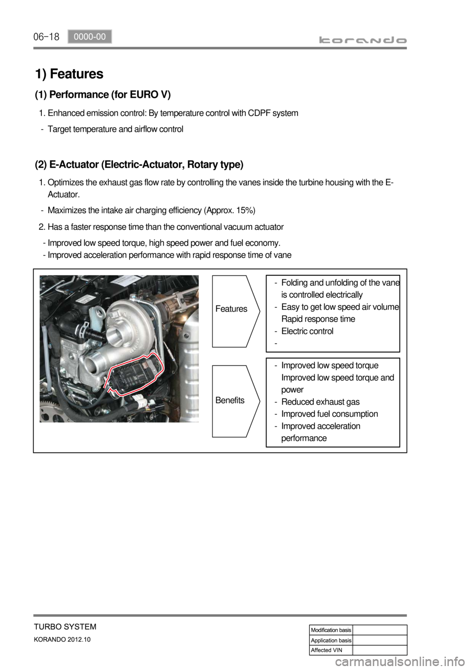
Maximizes the intake air charging efficiency (Approx. 15%) -Optimizes the exhaust gas flow rate by controlling the vanes inside the turbine housing with the E-
Actuator. 1.
(2) E-Actuator (Electric-Actuator, Rotary type)
Target temperature and airflow control -Enhanced emission control: By temperature control with CDPF system 1.
(1) Performance (for EURO V)
Has a faster response time than the conventional vacuum actuator 2.
Improved low speed torque, high speed power and fuel economy.
Improved acceleration performance with rapid response time of vane -
-
1) Features
Features
BenefitsFolding and unfolding of the vane
is controlled electrically
Easy to get low speed air volume
Rapid response time
Electric control -
-
-
-
Improved low speed torque
Improved low speed torque and
power
Reduced exhaust gas
Improved fuel consumption
Improved acceleration
performance -
-
-
-
Page 219 of 1082
09-70000-00
(1) Checking
Using battery tester ▶
PASS (11.0 V or more): Explain to the customer that the battery is reusable.
Need to be charged (9.0 to 11.0 V): Charge the battery with a charger and reinstall it. Explain it to the
customer.
Need to be replaced (9.0 V or more): The battery should be replaced due to overdischarging. -
-
-
(2) How to use battery tester
How it works and How to use it ▶
Determine battery capacity by fixing current
(load capacity) and time and varying voltage.
Determine battery capacity based on the
amount of voltage drop when discharging a
fixed load capacity (120 A) for 5 seconds.
Connect the tester to the battery and read the
display while applying a load for 5 seconds. -
-
-
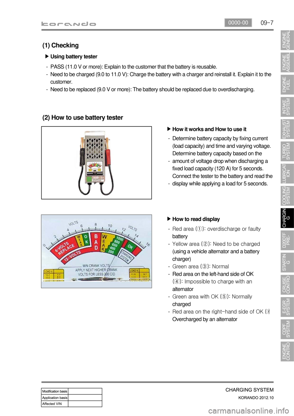
How to read display ▶
Red area (①): overdischarge or faulty
battery
Yellow area (②): Need to be charged
(using a vehicle alternator and a battery
charger)
Green area (③): Normal
Red area on the left-hand side of OK
(④): Impossible to charge with an
alternator
Green area with OK (⑤): Normally
charged
Red area on the right-hand side of OK (
⑥
Overcharged by an alternator -
-
-
-
-
-
Page 223 of 1082
09-110000-00
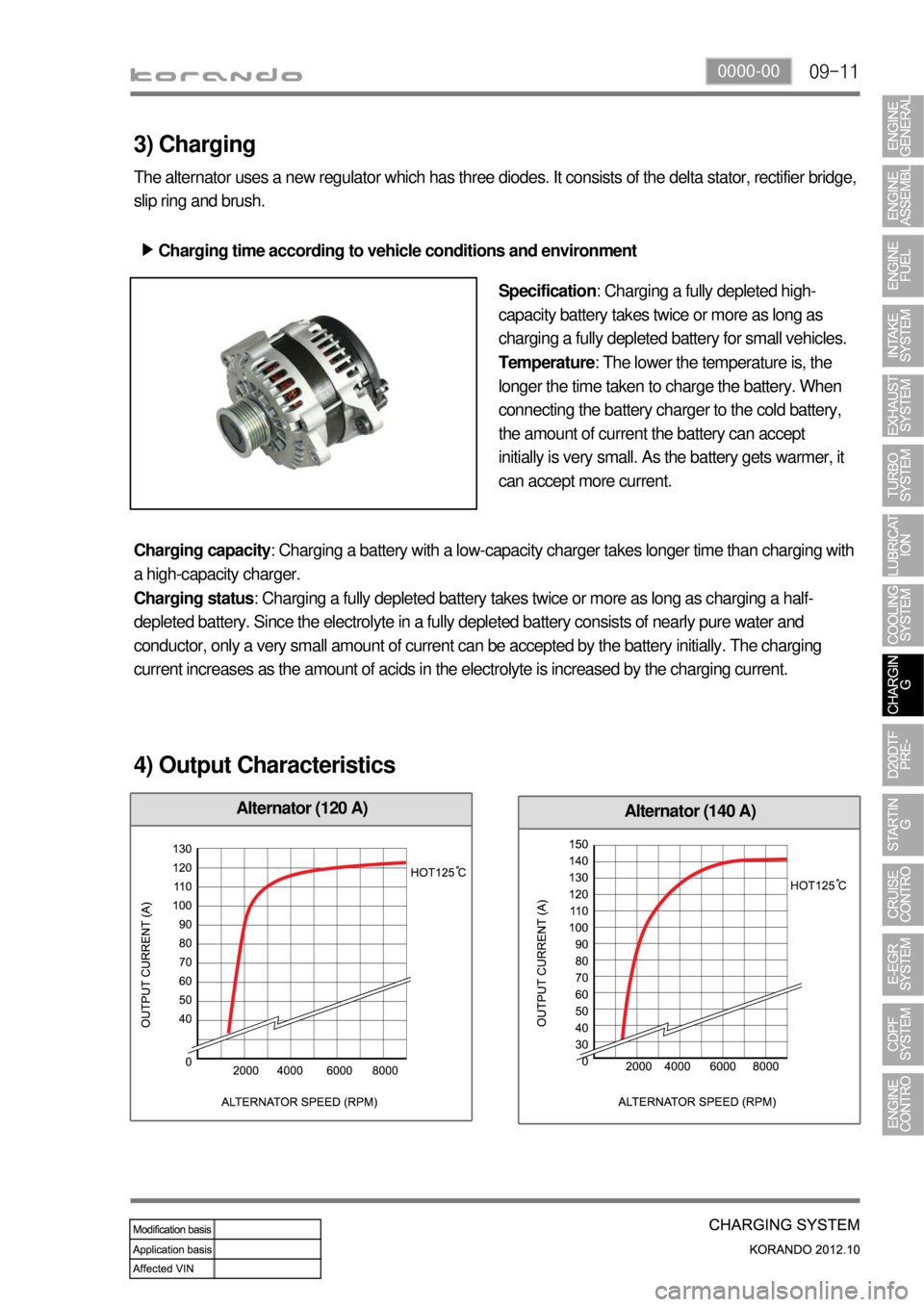
Alternator (140 A)Alternator (120 A)
3) Charging
The alternator uses a new regulator which has three diodes. It consists of the delta stator, rectifier bridge,
slip ring and brush.
Charging time according to vehicle conditions and environment ▶
Specification: Charging a fully depleted high-
capacity battery takes twice or more as long as
charging a fully depleted battery for small vehicles.
Temperature: The lower the temperature is, the
longer the time taken to charge the battery. When
connecting the battery charger to the cold battery,
the amount of current the battery can accept
initially is very small. As the battery gets warmer, it
can accept more current.
Charging capacity: Charging a battery with a low-capacity charger takes longer time than charging with
a high-capacity charger.
Charging status: Charging a fully depleted battery takes twice or more as long as charging a half-
depleted battery. Since the electrolyte in a fully depleted battery consists of nearly pure water and
conductor, only a very small amount of current can be accepted by the battery initially. The charging
current increases as the amount of acids in the electrolyte is increased by the charging current.
4) Output Characteristics
Page 224 of 1082
09-12
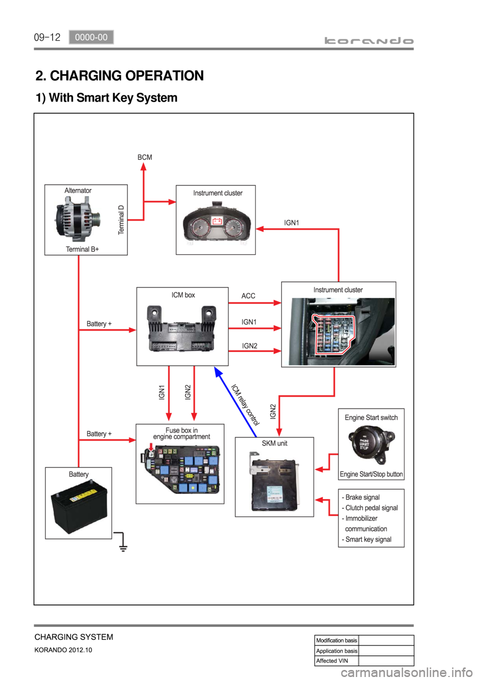
2. CHARGING OPERATION
1) With Smart Key System
Page 445 of 1082
09-91452-01
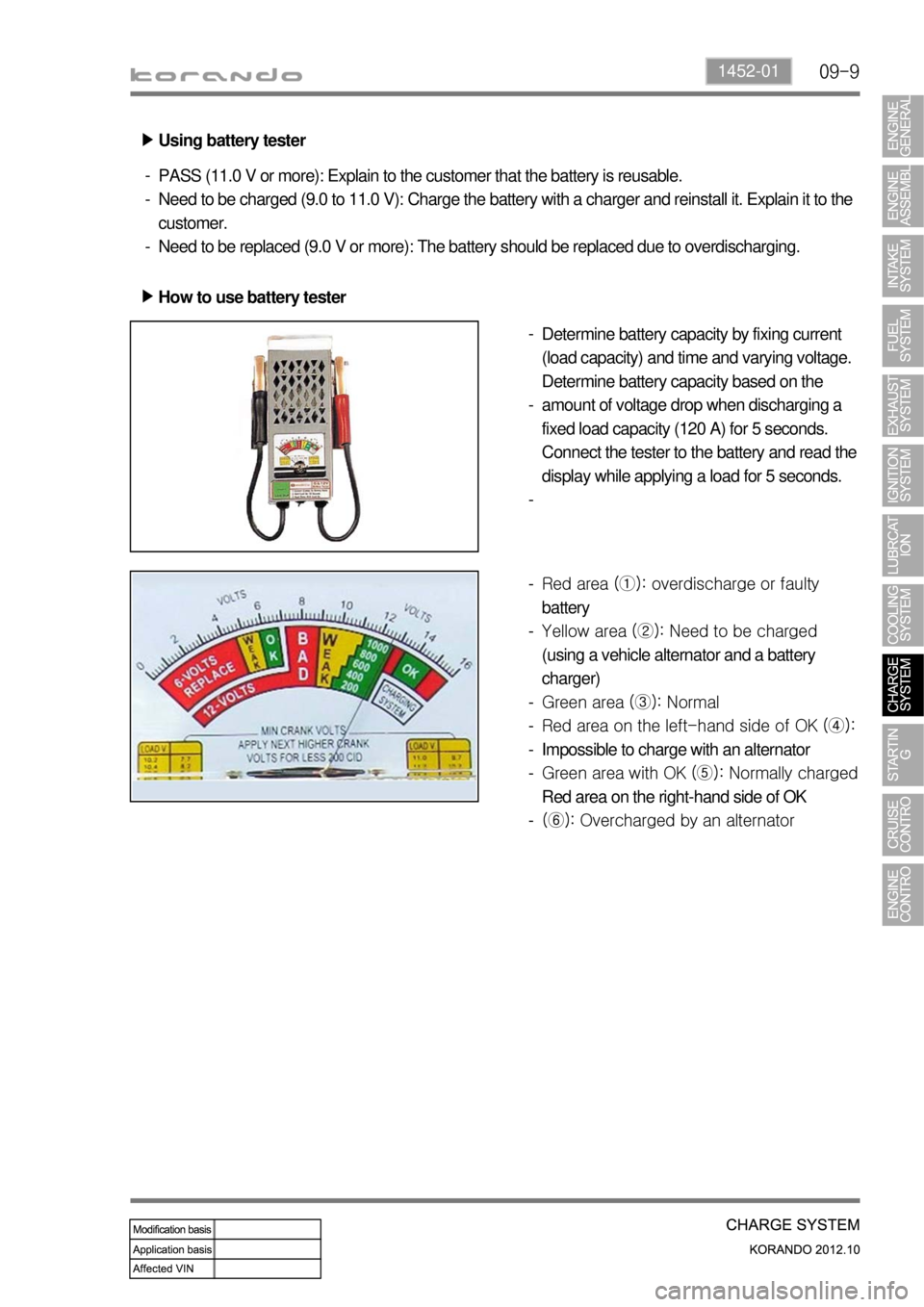
Using battery tester ▶
PASS (11.0 V or more): Explain to the customer that the battery is reusable.
Need to be charged (9.0 to 11.0 V): Charge the battery with a charger and reinstall it. Explain it to the
customer.
Need to be replaced (9.0 V or more): The battery should be replaced due to overdischarging. -
-
-
How to use battery tester ▶
Determine battery capacity by fixing current
(load capacity) and time and varying voltage.
Determine battery capacity based on the
amount of voltage drop when discharging a
fixed load capacity (120 A) for 5 seconds.
Connect the tester to the battery and read the
display while applying a load for 5 seconds. -
-
-
Red area (①): overdischarge or faulty
battery
Yellow area (②): Need to be charged
(using a vehicle alternator and a battery
charger)
Green area (③): Normal
Red area on the left-hand side of OK (④):
Impossible to charge with an alternator
Green area with OK (⑤): Normally charged
Red area on the right-hand side of OK
(⑥): Overcharged by an alternator -
-
-
-
-
-
-
Page 449 of 1082
09-131452-01
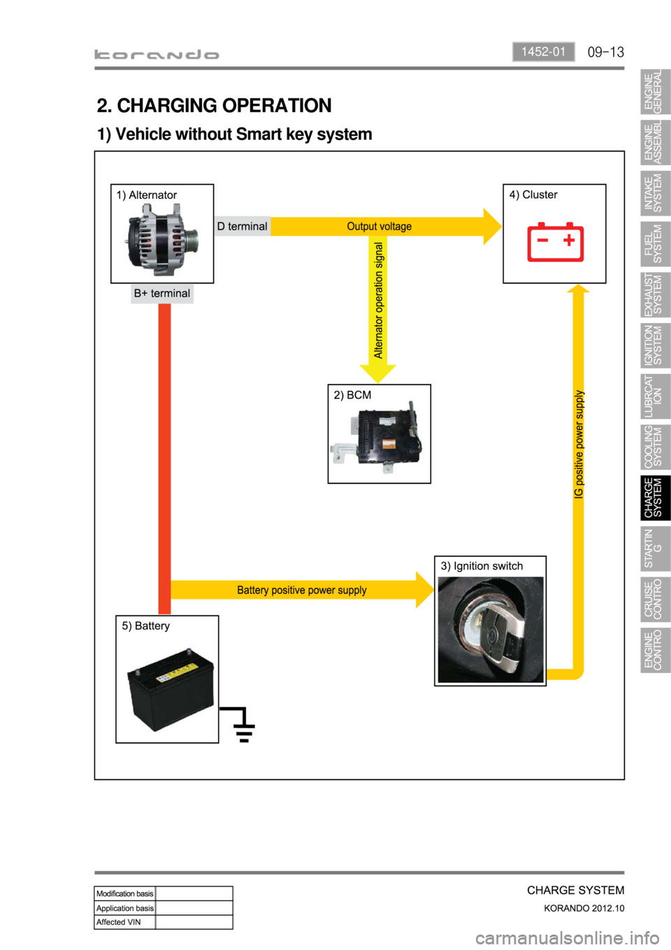
2. CHARGING OPERATION
1) Vehicle without Smart key system
Page 514 of 1082
14-8
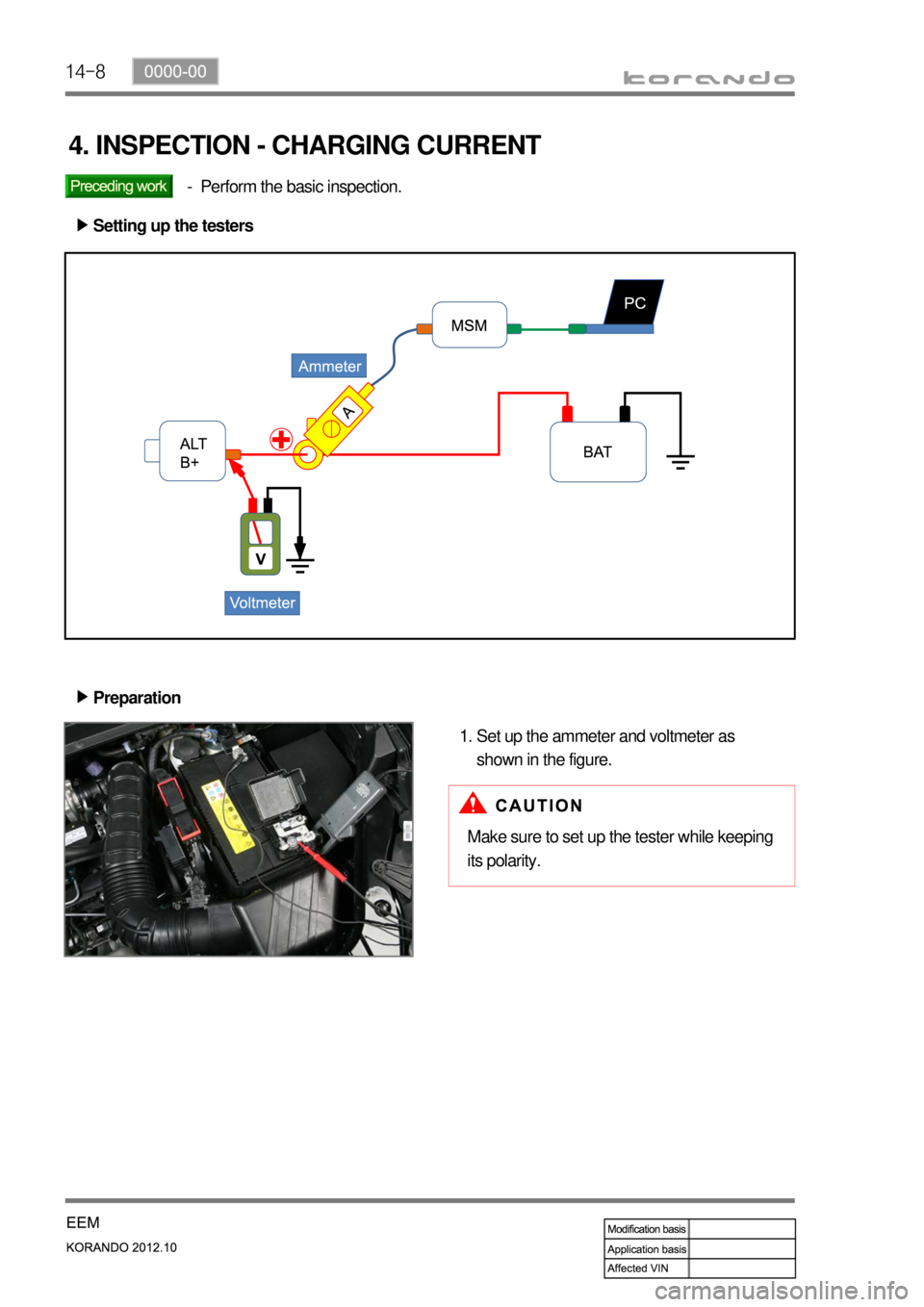
4. INSPECTION - CHARGING CURRENT
Perform the basic inspection. -
Setting up the testers ▶
Preparation ▶
Set up the ammeter and voltmeter as
shown in the figure. 1.
Make sure to set up the tester while keeping
its polarity.
Page 519 of 1082
14-130000-00
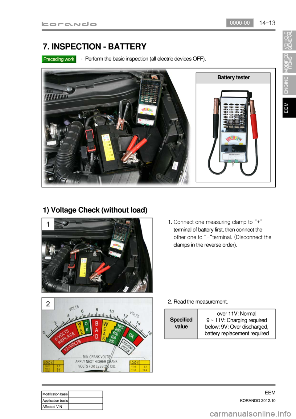
Specified
valueover 11V: Normal
9 ~ 11V: Charging required
below: 9V: Over discharged,
battery replacement required
7. INSPECTION - BATTERY
Perform the basic inspection (all electric devices OFF). -
Battery tester
1) Voltage Check (without load)
Connect one measuring clamp to “+”
terminal of battery first, then connect the
other one to “-“terminal. (Disconnect the
clamps in the reverse order). 1.
Read the measurement. 2.
Page 520 of 1082
14-14
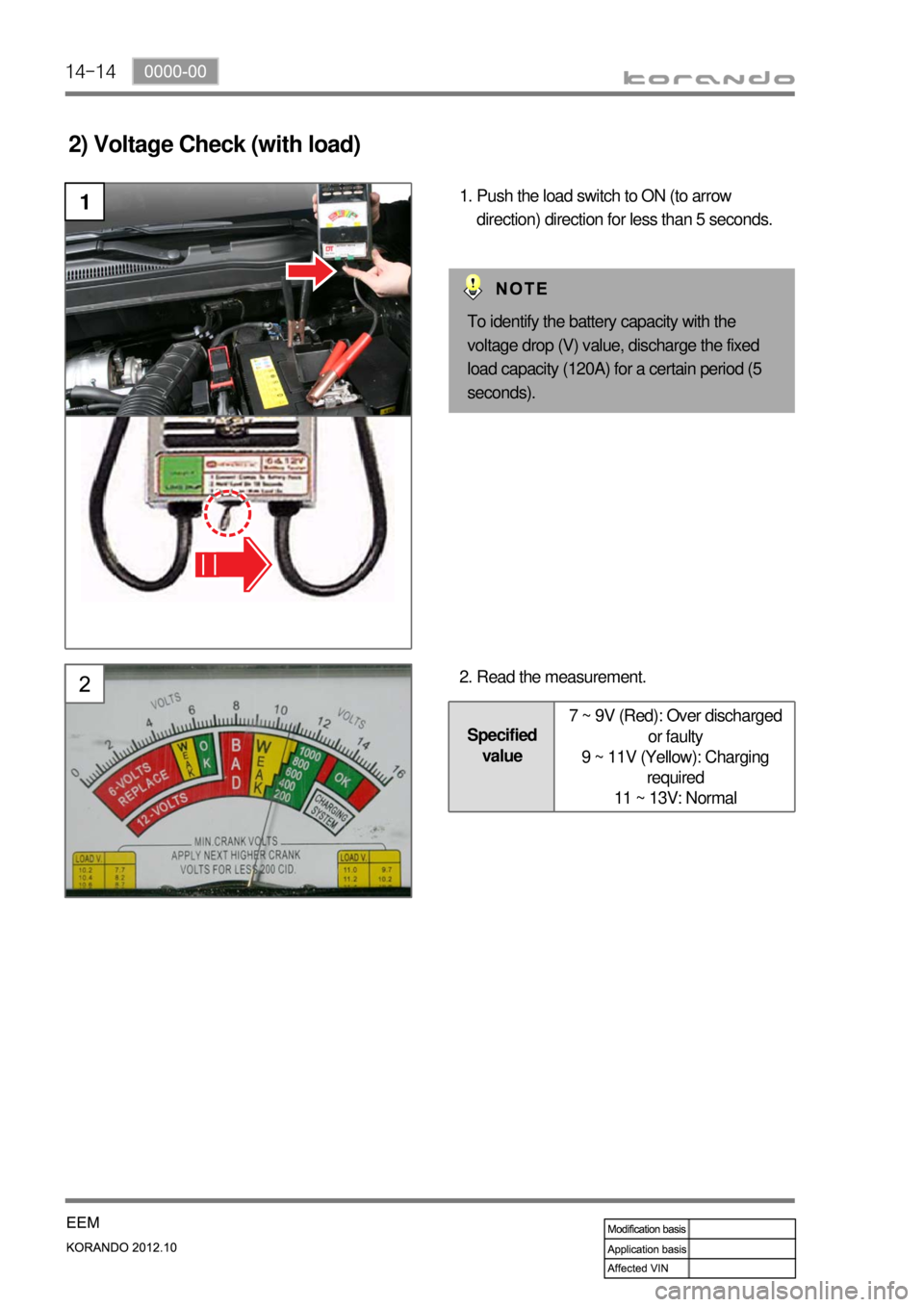
2) Voltage Check (with load)
1Push the load switch to ON (to arrow
direction) direction for less than 5 seconds. 1.
Read the measurement. 2.
Specified
value7 ~ 9V (Red): Over discharged
or faulty
9 ~ 11V (Yellow): Charging
required
11 ~ 13V: Normal
To identify the battery capacity with the
voltage drop (V) value, discharge the fixed
load capacity (120A) for a certain period (5
seconds).
Page 523 of 1082
14-170000-00
2. OPERATING PROCESS
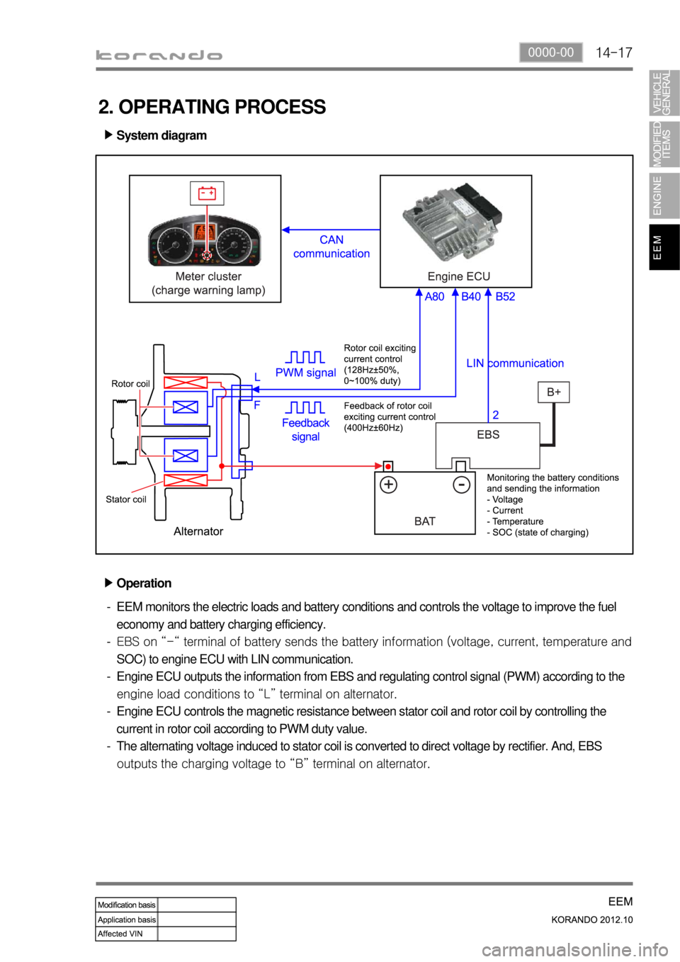
System diagram ▶
Operation ▶
EEM monitors the electric loads and battery conditions and controls the voltage to improve the fuel
economy and battery charging efficiency.
EBS on “-“ terminal of battery sends the battery information (voltage, current, tem
perature and
SOC) to engine ECU with LIN communication.
Engine ECU outputs the information from EBS and regulating control signal (PWM) according to the
<008c0095008e00900095008c0047009300960088008b0047008a00960095008b0090009b009000960095009a0047009b0096004702c8007302c90047009b008c009900940090009500880093004700960095004700880093009b008c009900950088009b00
9600990055>
Engine ECU controls the magnetic resistance between stator coil and rotor coil by controlling the
current in rotor coil according to PWM duty value.
The alternating voltage induced to stator coil is converted to direct voltage by rectifier. And, EBS
<0096009c009b0097009c009b009a0047009b008f008c0047008a008f00880099008e00900095008e0047009d00960093009b0088008e008c0047009b0096004702c8006902c90047009b008c00990094009000950088009300470096009500470088009300
9b008c009900950088009b009600990055> -
-
-
-
-