SSANGYONG KORANDO 2012 Service Manual
Manufacturer: SSANGYONG, Model Year: 2012, Model line: KORANDO, Model: SSANGYONG KORANDO 2012Pages: 1082, PDF Size: 96.1 MB
Page 1031 of 1082

02-158810-00
Collision signal interface ▶
The open collector driver raises or lowers the voltage of the pin no. 58 by switching on and off the drive
transistor. The vehicle module can be operated normally only by the logic of open collector interface
and can be maintained in a pull-up state. The followings are the specifications of the electrical interface.
The load resistance of the SDM is 590 ohms or higher. It may not be possible to operate the collision
occurrence circuit normally if the resistance value is not as specified.
Pin No. Minimum Average Maximum Remark
Driving current (current value
when the transistor is turned
on) 12.31 mA 19.6 mA 30 mA Depending on the
battery voltage
Leakage current (current value
when the transistor is turned
off) 147.6 μA 376 μA No crash signal
Load resistance 590 ohms Above than this value
Page 1032 of 1082

02-16
3) CAN Communication Interface (FIS and SIS)
The CAN communication interface uses the PWM for the supply current and the current loop and
communicates with the SDM to transmit the information. The serial communication and power for the
satellite are supplied through the communication line.
Stage FIS SIS
Initial stage Tracking/Check (Self test) Same as FIS
Normal operation Checks the FIS condition and sends the result as
"OK" or "NOK", and also sends the "severity" of the
crash. Same as FIS
Voltage The FIS hardware reset was performed under 5 V,
communication voltage low Same as FIS
Fault The fault is found in the current ignition cycle but the
fault is deactivated in the next ignition cycle. Multiple faults can be found
and deactivated in the same
ignition cycle.
The FIS moves to the initial stage if 'leakage to GND' is occurred in normal operating stage to shut down
the power and prevent abnormal operation.
※ FIS: Front Impact Sensor
SIS: Side Air bag Sensor
Page 1033 of 1082

02-178810-00
4. AIR BAG WARNING LAMP OPERATIONAL CONDITIONS
When there are no active and past faults ▶
The air bag warning lamp is operated as shown below if there is no fault occurred in the previous ignition
cycle and the SDM is running without any active fault right after starting the ignition cycle.
When there is no active fault and past faults occurred less than 10 times ▶
The warning lamp is operated as shown below every time the vehicle is started if the SDM is running
without any active fault in the entire time and past faults in the previous ignition cycle occurred within 10
times.
"Battery voltage too low" is not included in the past faults.
Page 1034 of 1082

02-18
When there is any active fault or past faults occurred 10 times or more ▶
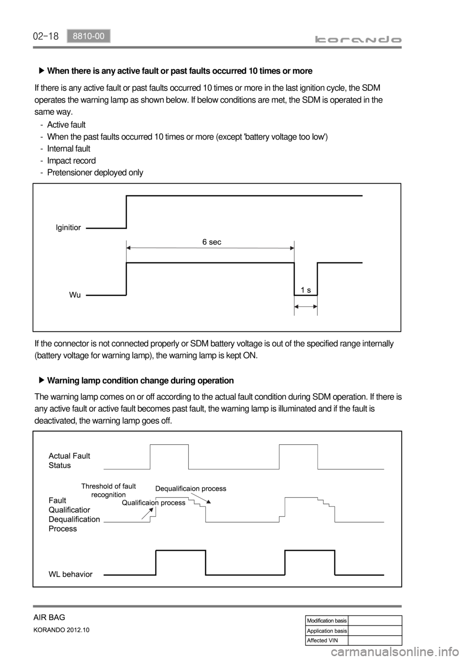
If there is any active fault or past faults occurred 10 times or more in the last ignition cycle, the SDM
operates the warning lamp as shown below. If below conditions are met, the SDM is operated in the
same way.
Active fault
When the past faults occurred 10 times or more (except 'battery voltage too low')
Internal fault
Impact record
Pretensioner deployed only -
-
-
-
-
If the connector is not connected properly or SDM battery voltage is out of the specified range internally
(battery voltage for warning lamp), the warning lamp is kept ON.
Warning lamp condition change during operation ▶
The warning lamp comes on or off according to the actual fault condition during SDM operation. If there is
any active fault or active fault becomes past fault, the warning lamp is illuminated and if the fault is
deactivated, the warning lamp goes off.
Page 1035 of 1082

02-198810-00
5. CIRCUIT DIAGRAM
8810-01 Air bag (Curtain air bag/Side air bag) ▶
Page 1036 of 1082

03-37410-00
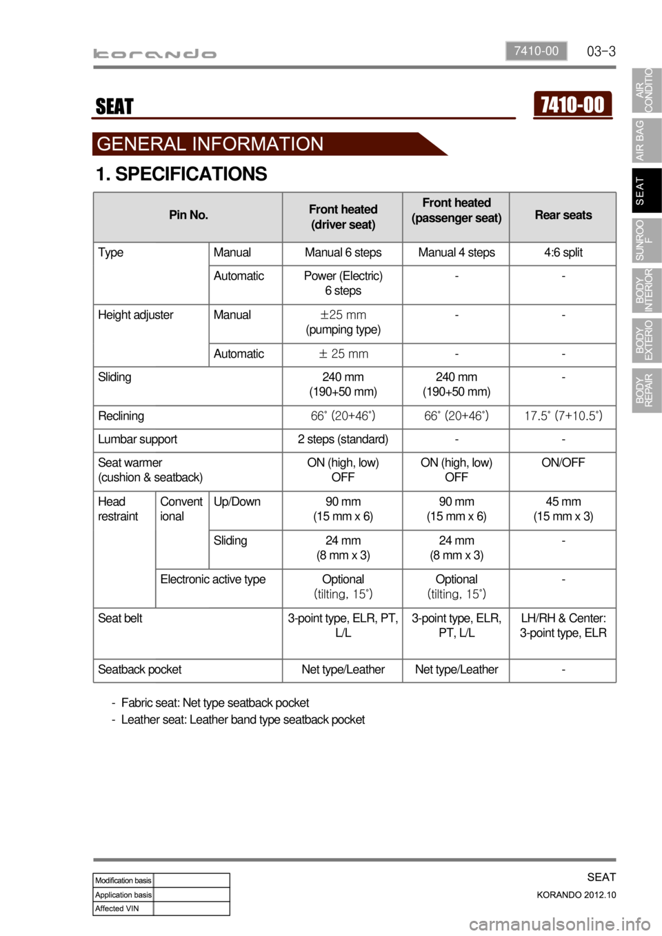
Pin No.Front heated
(driver seat)Front heated
(passenger seat)Rear seats
Type Manual Manual 6 steps Manual 4 steps 4:6 split
Automatic Power (Electric)
6 steps--
Height adjuster Manual±25 mm
(pumping type)--
Automatic± 25 mm--
Sliding 240 mm
(190+50 mm)240 mm
(190+50 mm)-
Reclining66˚ (20+46˚) 66˚ (20+46˚) 17.5˚ (7+10.5˚)
Lumbar support 2 steps (standard) - -
Seat warmer
(cushion & seatback)ON (high, low)
OFFON (high, low)
OFFON/OFF
Head
restraintConvent
ional Up/Down 90 mm
(15 mm x 6)90 mm
(15 mm x 6)45 mm
(15 mm x 3)
Sliding 24 mm
(8 mm x 3)24 mm
(8 mm x 3)-
Electronic active type Optional
(tilting, 15˚)Optional
(tilting, 15˚)-
Seat belt 3-point type, ELR, PT,
L/L3-point type, ELR,
PT, L/LLH/RH & Center:
3-point type, ELR
Seatback pocket Net type/Leather Net type/Leather -
1. SPECIFICATIONS
Fabric seat: Net type seatback pocket
Leather seat: Leather band type seatback pocket -
-
Page 1037 of 1082

03-4
2. WARNINGS FOR POWER SEAT
Adjust the driver's seat before driving.
Make sure that the seat is firmly secured after adjusting.
Never drive the vehicle with the head restraint removed or lowered excessively. Otherwise, you
r
neck, spine or other parts of the body can be severely injured in the event of an accident.
If you recline the seatback excessively, you could slide under the seat belt and be injured severely
in a collision.
Do not put any object that could damage the seat on the seat.
The front and rear seats are equipped with the heated wire (seat warmer) system. Using the seat
warmer system excessively may cause minor burns. The following occupants should exercise
special care when using the heated wire seat. ▷
▷
▷
▷
▷
▷
Infant, child, old or handicapped person
Person with sensitive skin
Exhausted person
Persons who is drunk or took medicine which causes drowsiness such as sleeping pills, cold
tablets, etc. -
-
-
-
Do not place anything on the seat that insulates against the heat, such as a blanket or cushion.
Make sure that the head restraints are in place and secured properly. Never drive the vehicle with
the head restraint removed.
To minimize the injuries in a collision or an abrupt stop, make sure the seatback is in the upright
position before driving. If the seatback is reclined too much, the occupant could slide under the seat
belt in a collision or an abrupt stop and cannot be protected properly by the airbag system. ▷
▷
▷
3. CAUTIONS FOR POWER SEAT
You can operate the power seat with the ignition switch OFF. However, frequent operation of the
seat switch with the engine stopped can result in battery becoming discharged.
Operating more than one seat adjustment switch at the same time can cause damage to the seat
motor. Therefore, operate the seat switch only one at a time.
Do not use organic solvents such as benzene, thinner, alcohol or gasoline to prevent the seat cove
r
from being damaged while cleaning.
Do not operate the seat position adjustment switch forcefully when the seat does not move or it
contacts an object.
If the power seat is not operated, check and correct the problem before driving off. ▷
▷
▷
▷
▷
Page 1038 of 1082

03-57410-00
Rear center seat belt
Previous Current
2-point type 3-point type
4. MAJOR CHANGES
1) Rear Center Seat Belt
2) Front Seat Back Board
Front seat back board
Previous Current
Hook: Installed
Pocket: Net typeHook: Not installed
Pocket: Fabric seat - Net type
Leather seat - Band type
Page 1039 of 1082

03-6
3) Front Buckle
Front buckle
Previous Current
Pad is attached to buckle No pad is attached to buckle
Front buckle
Driver's
Page 1040 of 1082

04-37340-00
1. SPECIFICATIONS
2. CAUTIONS WHEN WORKING
Wear clean work clothes and gloves.
Replace and wash the gloves frequently.
Any unauthorized modification or operational test is not allowed since the sunroof motor and control
unit are preset at the factory.
You can use basic tools, e.g. a 25T/10T star screwdriver, flat-bladed and cross-tip screwdrivers. Do
not use any similar tool.
Take care not to drop the sunroof assembly when removing it and do not keep it right up. 1.
2.
3.
4.
5.
Operating voltage 9 to 16 V
Operating current (open & close) Max. 6 A
At no load Approx. 3 A
Leakage current Max. 1 mA or less
Roof motor operating speed
(at opening and closing)1.4 ± 0.5 sec./100 mm
Motor overload stop conditionsCurrent for 25 A or higher and torque (load) for 7.5 Nm
or higher
2-step opening amount1st step sliding open: 370 ± 5 mm
2nd step sliding open: 450 ± 5 mm
Vertical/horizontal tolerance for
sunroof glass panel± 2 mm