SSANGYONG KORANDO 2012 Service Manual
KORANDO 2012
SSANGYONG
SSANGYONG
https://www.carmanualsonline.info/img/67/57504/w960_57504-0.png
SSANGYONG KORANDO 2012 Service Manual
Trending: odometer, Glow plug, warning, oil filter, belt, service schedule, gas type
Page 1001 of 1082
15-74012-00
2) Sectional Diagram and Bolts for Rear Sub Frame
Installation Sectional structure
1. Front
4WD 2WD
2. Rear
4WD 2WD
3. Rear axle - Front
(4WD)
4. Rear axle - rear
(4WD)
Page 1002 of 1082
15-8
The front sub frame consists of 4 body bush mountings(A) and 2 engine bush mountings(B) which
reduce the vibration from the powertrain and road, and also control the torque. And the two engine bush
mountings consist of an engine mounting which supports the engine powertrain and a transmission
mounting.
The engine side and transmission side mountings are rubber mountings with brackets and insulators
while the body mounting is a rubber bush mounting which is fitted to the frame.
Installation of front sub
frame (4WD)The installation of the front sub frame is the same for both automatic
transmission and manual transmission. For 4WD, the PTU and the
propeller shaft are installed.
Installation of front sub
frame (2WD)The installation of the front sub frame is the same for both automatic
transmission and manual transmission.
PTU assembly
Page 1003 of 1082
15-94015-01
Installation of rear sub
frame (4WD)The installation of the rear sub frame is the same for both automatic
transmission and manual transmission. For 4WD, the E-coupling, propeller
shaft and rear axle are installed.
Installation of rear sub
frame (2WD) The installation of the rear sub frame is the same for both automatic
transmission and manual transmission.
The rear sub frame system consists of body bush mountings and direct mountings which reduce the
vibration transmitted from the powertrain and road to the vehicle body.
For 4WD, it consists of 4 body mountings (bush mountings) and 2 axle mountings (bush mountings) and
for 2WD, it consists of 4 body mountings (direct mountings).
Page 1004 of 1082
01-36810-00
1. SPECIFICATION
Description Specification
HeaterCore size (㎣)200 x 165.5 x 25
Capacity (kcal/h) 4,800
EvaporatorCore size (㎣)254.8 x 196.75 x 60
Capacity (kcal/h) 4,700
Blower Supply power (W) 240 + 10% Max (at 12 V)
Fan speed (rpm)2900±200 Max
(Rec.Mode: 420㎥/h)
PTC Supply power 1 kW
CondenserCore size (㎣)588 x 455 x 16 (2,625)
Capacity (kcal/h) 12,000
Capacity of receiver drier 250 cc
compressor Capacity 170 cc/rev
Diameter of pulleyØ120
Max. continuous speed 8,000 rpm
voltage DC 12 V
Power consumption 2.2 A
Page 1005 of 1082
01-4
2. MAJOR CHANGES
1) Heater & Evaporator Module (Wiring Specification)
The driving circuit for the manual A/C ambient temperature sensor is added, giving the change to the
heater and evaporator module.
Ambient temperature sensor signal wiring
added to vehicle wiring connecting
connector (2 circuits)
: manual A/CBlower max signal wiring added to
vehicle wiring connecting connector
(1 circuit)
: manual A/C & FATC
Manual A/C: Wiring pin added to controller assembly connector
FATC: Wiring pin added to existing connector of controller assembly
Page 1006 of 1082
01-56810-00
2) Manual A/C Controller
Manual air conditioner controller
Previous Current
The driving circuit for the ambient temperature sensor is added to the manual air conditioner controller
for ambient temperature display on the instrument cluster.
Connector added
Pin No. Function
B1 -
B2 -
B3 -
B4 Water temp. signal
B5 -
B6 -
B7 -
B8 -
B9 -
B10 Sun-load sensor signal
B11 Ambient temp. sensor signal
B12 -
Page 1007 of 1082
01-6
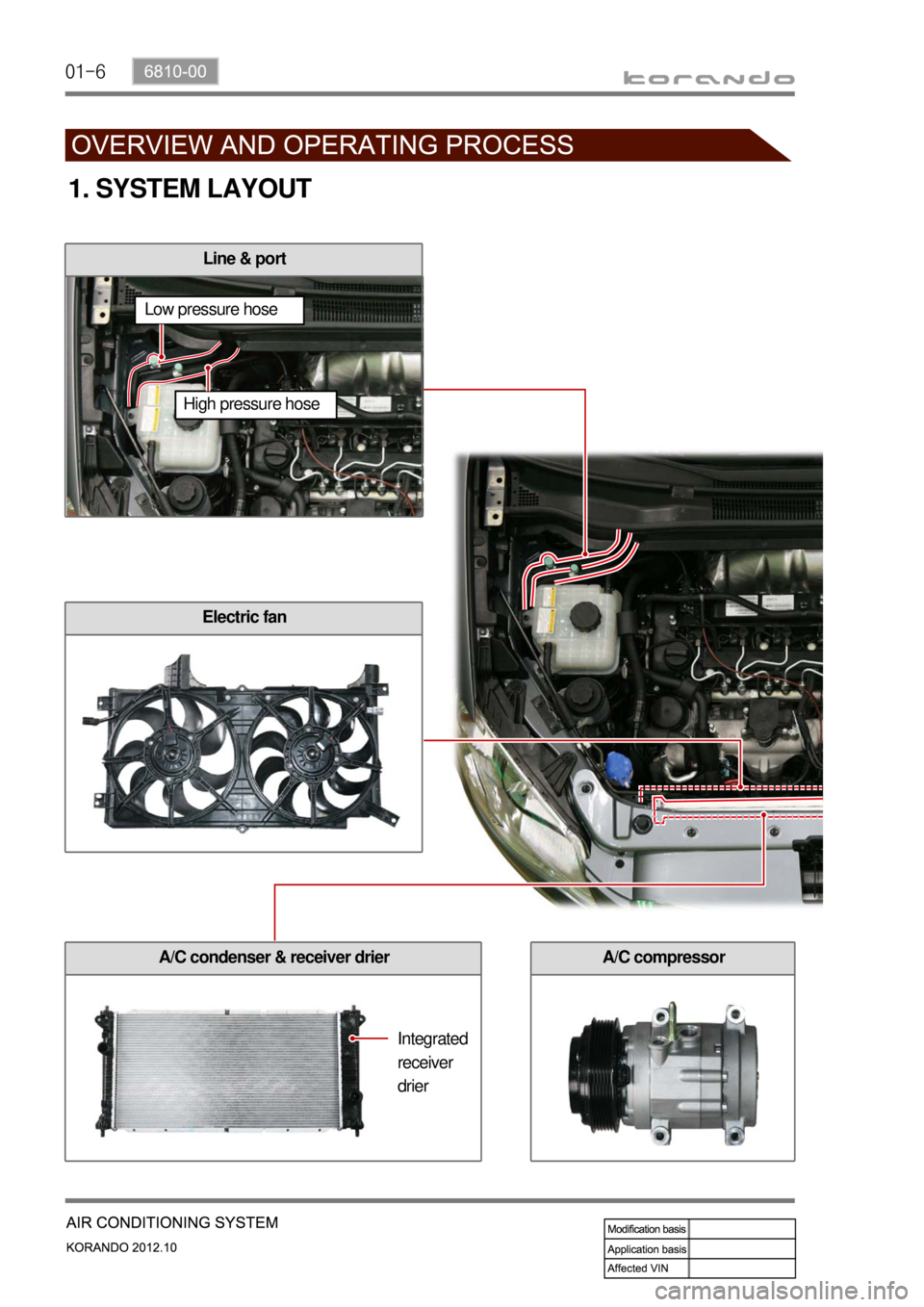
1. SYSTEM LAYOUT
Line & port
A/C compressor
Electric fan
A/C condenser & receiver drier
Integrated
receiver
drier
High pressure hose Low pressure hose
Page 1008 of 1082
01-76810-00
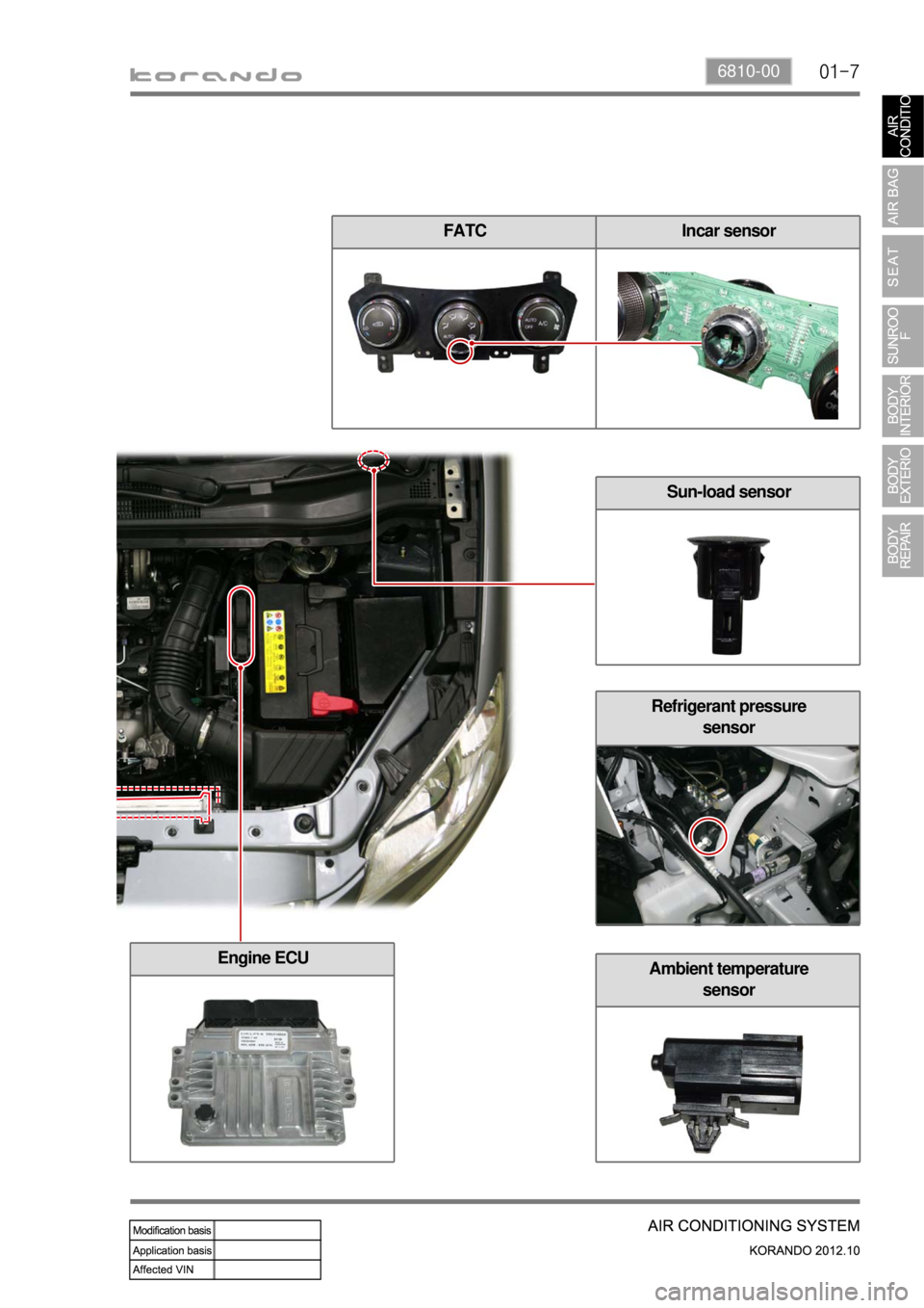
FATC Incar sensor
Refrigerant pressure
sensor
Ambient temperature
sensor
Sun-load sensor
Engine ECU
Page 1009 of 1082
01-8
Recirculation switch Temperature dial
Mode dialFan speed dial
A/C switch
Recirculation switch
When you press this switch,
recirculation indicator comes on
and the system is changed into the
recirculation mode.
(However, under defroster mode or
defroster/floor mode, it stays in the
fresh air mode.) -
1) Full Automatic A/C Control
2. HEATER AND A/C CONTROL
To adjust the temperature, turn this
dial as required. Turning the dial to HI
increases the temperature and LO
decreases the temperature. - Temperature dial
Temperature dial ▶
Page 1010 of 1082
01-96810-00
Incar sensor
This sensor detects the inside temperature and
installed in PCB.Face-Level
(vent mode)Face/Foot-Level
(bi-level mode)Foot-Level
(foot mode)
Foot/Defrost-level
(foot/defrost mode)
Defroster switch
Use this switch to remove for or
ice from the windshield. When
choosing this mode, the airflow
direction will be changed to the
windshield and side glasses, the
air conditioner operates
automatically, and fresh air
comes in. The air flow direction can be controlled by turning the dial. -
Airflow is changed
automatically according to the
setting temperature.
Fan speed dial
Manual control
Fan speed is manually controlled b
y
this dial. The increment is 1℃.
Auto control
Fan speed is automatically
controlled by temperature setting.
The blower motor operates in a
stepless mode. -
-
A/C switch
When pressing this switch,
the air conditioner operates
in manual mode and A/C
ON indicator comes on.
Fan speed dial ▶Mode dial ▶
Trending: check engine, oil type, audio, spare wheel, automatic, checking oil, wheel size


