fuel SSANGYONG KORANDO 2012 Service Manual
[x] Cancel search | Manufacturer: SSANGYONG, Model Year: 2012, Model line: KORANDO, Model: SSANGYONG KORANDO 2012Pages: 1082, PDF Size: 96.1 MB
Page 736 of 1082

06-258510-00
SVC class instrument cluster
TRIP A TRIP B
(3) Trip switch
Whenever pressing this button, the information is displayed in the following order: Odometer, Trip A, Trip
B, Distance to empty, Average fuel consumption, Instant fuel consumption, Illumination level, Ambient air
temperature (for STD); Trip A, Trip B, Distance to empty, Average fuel consumption, Instant fuel
consumption, Illumination level, Ambient air temperature (for SVC). Press and hold (for more than 1 sec)
this button to initialize (reset) Trip A/Trip B and average fuel consumption, adjust illumination level or
change the unit of temperature.
Description ▶
The factory setting is DTE mode. ※ Display
Mode
SwitchDetecting
timeFunction
Briefly
and holdBelow 1
second
(60 to
980 ms)STD- Mode change
(Odo→Trip A→Trip B→DTE
<00470047004702e70068009d008c00990088008e008c0047008d009c008c00930047008a00960095009a009c00940097009b00900096009502e700700095009a009b00880095009b0047008d009c008c00930047008a00960095009a009c00940097009b00
9000960095>
→Illumination level→Ambient air temperature)
SVC- Mode change
(Trip A→Trip B→DTE→Average fuel consumption
→Instant fuel consumption→Illumination level
→Ambient air temperature)
Press
and holdOver 1
seconds- Reset
(Trip A, B, average fuel consumption)
- Change
<004700470047004f007000930093009c0094009000950088009b00900096009500470093008c009d008c00930047004f005d0047009b009600470058005000530047009b008c00940097008c00990088009b009c0099008c0047009c00950090009b004700
4f0b4502e90d9100500050>
Not
pressOver 3
seconds- Mode change
<004700470047004f007000930093009c0094009000950088009b00900096009500470093008c009d008c009302e70068009400890090008c0095009b00470088009000990047009b008c00940097008c00990088009b009c0099008c02e70076008b009600
50>
STD class instrument cluster
TRIP A TRIP B
Page 843 of 1082

02-93680-01
2. FEATURES
1) Advantages
Early Downshift with Hard Braking and Skip Shifts ▶
When heavy braking is detected, the transaxle downshifts early and skips gears to provide increased
engine braking to provide gear selection for tip-in.
Gear Hold going Uphill/Downhill ▶
If the accelerator pedal is released when traveling uphill, upshifts are prevented to reduce busyness on
grades. If the accelerator pedal is released when traveling downhill, upshifts are prevented to enhance
engine braking.
Drive and Reverse Engagement ▶
A soft engagement feature avoids harsh take up of drive when selecting Drive or Reverse. This is
achieved by limiting engine speed and engine torque which results in a rapid, but progressive
engagement of either Drive or Reverse when moving from the Park or Neutral positions. Drive and
Reverse engagements from either Park or Neutral are performed in less than 2.2 seconds. There is no
drive engagement prevention strategy implemented on the transaxle system as there is sufficient engine
strategy to protect the system. However, reverse engagement is prevented until engine speed is less
than 1,400 rpm and the accelerator pedal position is less than 12% and vehicle speed is less than 10
km/h.
Converter Clutch Lock-Up In All Gears ▶
The transaxle features converter clutch lock-up in all gears. This feature provides improved fuel economy
and vehicle performance. It also improves transaxle cooling efficiency when towing heavy loads at low
speeds, e.g. in city driving or hill terrain.
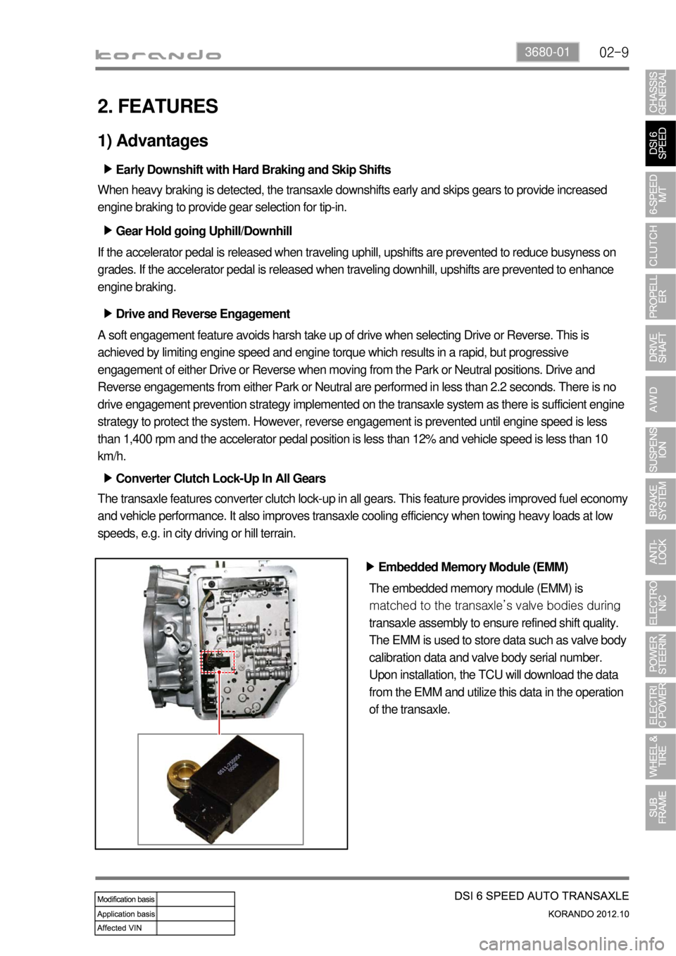
Embedded Memory Module (EMM) ▶
The embedded memory module (EMM) is
matched to the transaxle’s valve bodies during
transaxle assembly to ensure refined shift quality.
The EMM is used to store data such as valve body
calibration data and valve body serial number.
Upon installation, the TCU will download the data
from the EMM and utilize this data in the operation
of the transaxle.
Page 844 of 1082

02-10
2) Transaxle Cooling
The transaxle cooling system ensures rapid warm-up and constant operating temperature resulting in
reduced fuel consumption and refined shift quality.
It also includes a cooler by-pass within the hydraulic system to allow sufficient lubrication to the transaxle
drivetrain in the event of a blockage in the transaxle cooler.
3) Shift Strategy
Gear Change ▶
Transaxle gear change is controlled by the
TCU. The TCU receives inputs from various
engine and vehicle sensors to select shift
schedules and to control the shift feel and
torque converter clutch (TCC) operation at each
gear change.
Coast down ▶
Coast down down shifts occur at 0% pedal
when the vehicle is coasting down to a stop.
Torque Demand ▶
Torque demand down shifts occur
(automatically) when the driver demand for
torque is greater than the engine can provide at
that gear ratio. If applied, the transaxle will
disengage the TCC to provide added
acceleration.
Page 850 of 1082

02-16
3) Shift Map Selection
The driver can manually select between normal (S) and winter modes (W) via the mode switch.
Depending on the transaxle temperature, uphill and downhill grades and altitude, shift maps will be
selected by the TCU to suit the driving conditions. The following maps are available.
Standard (Normal) Mode ▶
Normal Mode is selected when the lever is in the D position with the mode switch in the normal (S)
position and the transaxle is within normal temperature ranges. Shift schedule points are optimised for
fuel efficiency and general driving conditions.
Uphill and Downhill Mode ▶
In this mode, depending on the load of the vehicle, adaptive shift maps are selected to progressively
adjust the shift points and torque converter lock points.
Altitude Mode ▶
Shift points are automatically adjusted at higher altitudes to compensate for changes in engine torque
where the torque produced by the engine is greatly reduced by the effects of reduced barometric
pressure and temperature.
Winter (W) Mode ▶
When winter mode is selected, starting in second gear is facilitated and the WINTER mode indicator
light is switched ON. To prevent wheel spin on slippery surfaces, the transmission will not allow first gear
unless manually overridden.
Warm up Schedule ▶
<007c009a008c008b0047009b00a000970090008a00880093009300a00047009e008f008c00950047009b009900880095009a0088009f0093008c0047008d0093009c0090008b0047009b008c00940097008c00990088009b009c0099008c00470090009a00
470089008c00930096009e00470059005700b6006a0055>
The torque converter will not lock-up below 20°C to assist in transaxle warm-up.
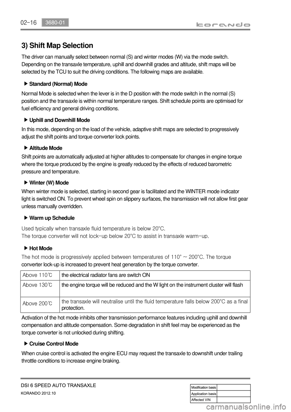
Hot Mode ▶
<007b008f008c0047008f0096009b004700940096008b008c00470090009a0047009700990096008e0099008c009a009a0090009d008c009300a0004700880097009700930090008c008b00470089008c009b009e008c008c00950047009b008c0094009700
8c00990088009b009c0099008c009a00470096008d00470058>10° ~ 200°C. The torque
converter lock-up is increased to prevent heat generation by the torque converter.
Activation of the hot mode inhibits other transmission performance features including uphill and downhill
compensation and altitude compensation. Some degradation in shift feel may be experienced as the
torque converter is not unlocked during shifting.
Cruise Control Mode ▶
When cruise control is activated the engine ECU may request the transaxle to downshift under trailing
throttle conditions to increase engine braking.
Above 110℃the electrical radiator fans are switch ON
Above 130℃the engine torque will be reduced and the W light on the instrument cluster will flash
Above 200℃the transaxle will neutralise until the fluid tem
perature falls below 200°C as a final
protection.
Page 873 of 1082

03-133660-01
2) Transaxle Cooling
The transaxle cooling system ensures rapid warm-up and constant operating temperature resulting in
reduced fuel consumption and refined shift quality.
It also includes a cooler by-pass within the hydraulic system to allow sufficient lubrication to the transaxle
drivetrain in the event of a blockage in the transaxle cooler.
3) Shift Strategy
Gear Change ▶
Transaxle gear change is controlled by the
TCU. The TCU receives inputs from various
engine and vehicle sensors to select shift
schedules and to control the shift feel and
torque converter clutch (TCC) operation at each
gear change.
Coast down ▶
Coast down down shifts occur at 0% pedal
when the vehicle is coasting down to a stop.
Torque Demand ▶
Torque demand down shifts occur
(automatically) when the driver demand for
torque is greater than the engine can provide at
that gear ratio. If applied, the transaxle will
disengage the TCC to provide added
acceleration.
Page 905 of 1082

04-90000-00
3. DUAL MASS FLYWHEEL (DMF)
The dual mass flywheel (DMF) is of having a mass divided into two halves.
While one mass is connected to the engine crankshaft, which is affected by the mass moment of inertia
of the engine, the other mass is affected by one of the transmission.
The divided dual masses are connected to the coil spring and damping system internally.
The DMF has the following benefits: ▶
Reducing fuel consumption by lowering engine speed
Reducing rattling noise and vehicle vibration in all driving ranges
Reducing synchronization wear
Facilitating gear change
Protecting power train parts by preventing excessive load from being delivered -
-
-
-
-
Primary flywheel
Secondary flywheel
Arc damper spring
Torque limiter
Ring gear 1.
2.
3.
4.
5.
Page 989 of 1082

13-6
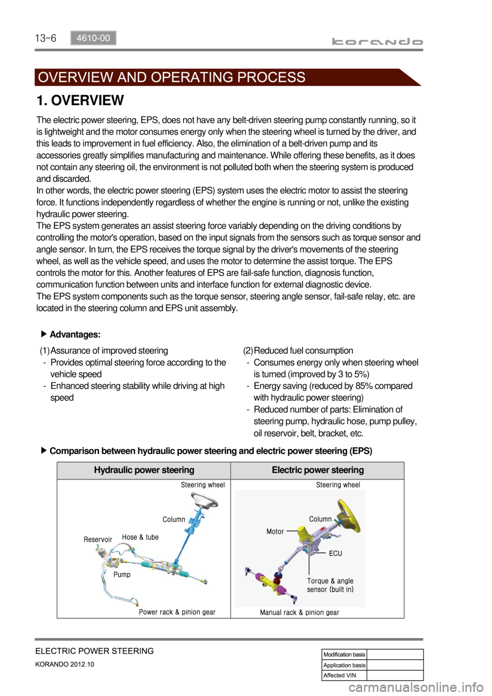
Hydraulic power steering Electric power steering
1. OVERVIEW
The electric power steering, EPS, does not have any belt-driven steering pump constantly running, so it
is lightweight and the motor consumes energy only when the steering wheel is turned by the driver, and
this leads to improvement in fuel efficiency. Also, the elimination of a belt-driven pump and its
accessories greatly simplifies manufacturing and maintenance. While offering these benefits, as it does
not contain any steering oil, the environment is not polluted both when the steering system is produced
and discarded.
In other words, the electric power steering (EPS) system uses the electric motor to assist the steering
force. It functions independently regardless of whether the engine is running or not, unlike the existing
hydraulic power steering.
The EPS system generates an assist steering force variably depending on the driving conditions by
controlling the motor's operation, based on the input signals from the sensors such as torque sensor and
angle sensor. In turn, the EPS receives the torque signal by the driver's movements of the steering
wheel, as well as the vehicle speed, and uses the motor to determine the assist torque. The EPS
controls the motor for this. Another features of EPS are fail-safe function, diagnosis function,
communication function between units and interface function for external diagnostic device.
The EPS system components such as the torque sensor, steering angle sensor, fail-safe relay, etc. are
located in the steering column and EPS unit assembly.
Advantages: ▶
Assurance of improved steering
Provides optimal steering force according to the
vehicle speed
Enhanced steering stability while driving at high
speed (1)
-
-Reduced fuel consumption
Consumes energy only when steering wheel
is turned (improved by 3 to 5%)
Energy saving (reduced by 85% compared
with hydraulic power steering)
Reduced number of parts: Elimination of
steering pump, hydraulic hose, pump pulley,
oil reservoir, belt, bracket, etc. (2)
-
-
-
Comparison between hydraulic power steering and electric power steering (EPS) ▶