SSANGYONG KORANDO 2012 Service Manual
KORANDO 2012
SSANGYONG
SSANGYONG
https://www.carmanualsonline.info/img/67/57504/w960_57504-0.png
SSANGYONG KORANDO 2012 Service Manual
Page 337 of 1082
01-130000-00
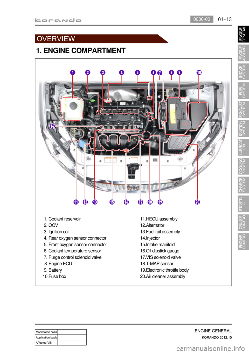
1. ENGINE COMPARTMENT
Coolant reservoir
OCV
Ignition coil
Rear oxygen sensor connector
Front oxygen sensor connector
Coolant temperature sensor
Purge control solenoid valve
Engine ECU
Battery
Fuse box 1.
2.
3.
4.
5.
6.
7.
8
9.
10.HECU assembly
Alternator
Fuel rail assembly
Injector
Intake manifold
Oil dipstick gauge
VIS solenoid valve
T-MAP sensor
Electronic throttle body
Air cleaner assembly 11.
12.
13.
14.
15.
16.
17.
18.
19.
20.
Page 338 of 1082
01-14
Engine ECU
2. FUEL SYSTEM
Engine compartment
Purge control solenoid
valveFuel railInjector
Page 340 of 1082
01-16
3. IGNITION SYSTEM
Ignition coilIgnition plugEngine ECU
Knock sensorCamshaft position
sensorCrankshaft position
sensor
Page 342 of 1082
01-18
WCCEngine CHECK
warning lampEngine ECU
Exhaust manifoldPCV valveBlow-by hose
Green
5. EXHAUST SYSTEM
Page 344 of 1082
01-20
Oil pumpOil panOil filter module
6. LUBRICATION SYSTEM
Oil pressure switchOil jetEngine oil gauge
Page 346 of 1082
01-22
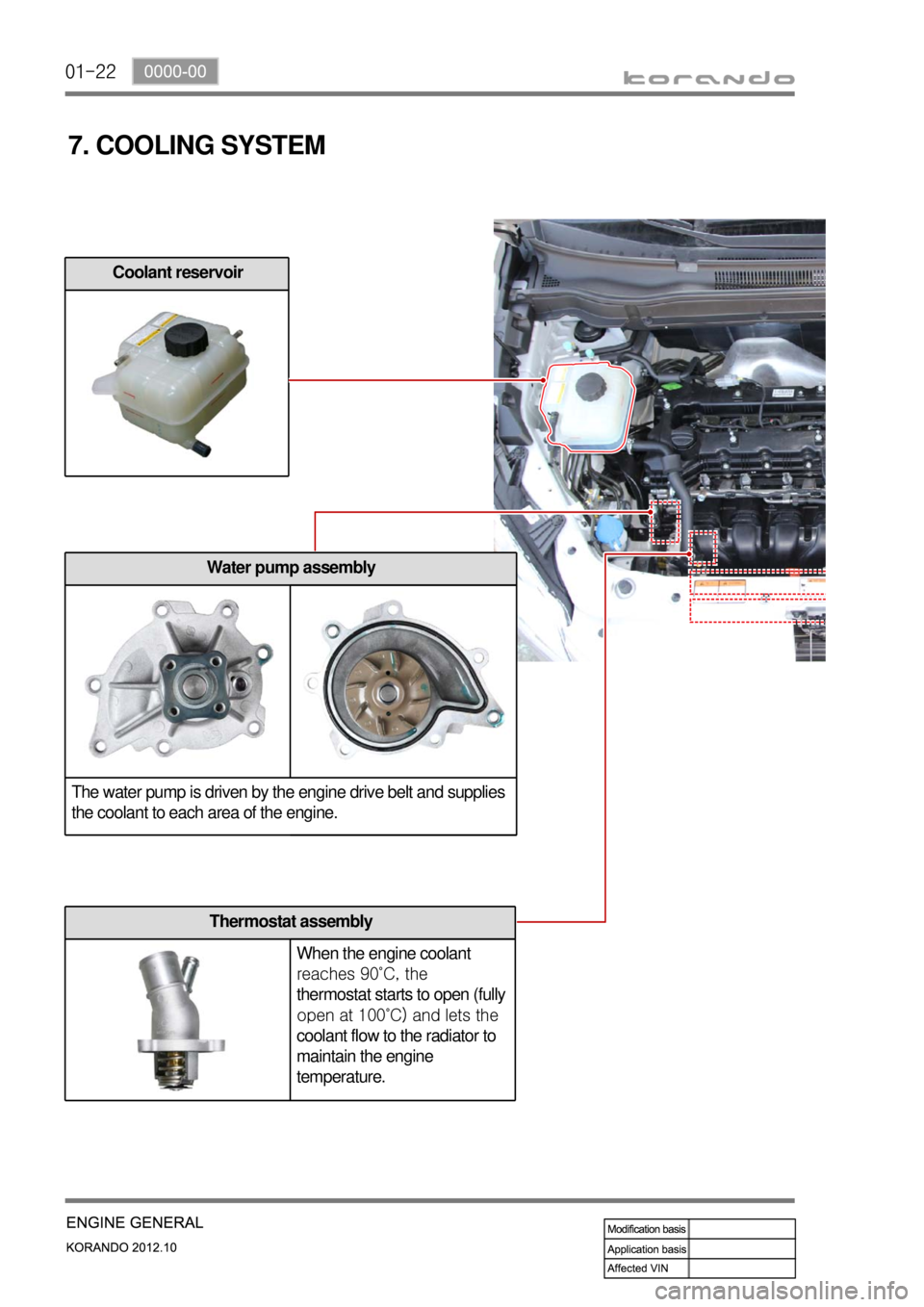
7. COOLING SYSTEM
Coolant reservoir
Water pump assembly
The water pump is driven by the engine drive belt and supplies
the coolant to each area of the engine.
Thermostat assembly
When the engine coolant
reaches 90˚C, the
thermostat starts to open (fully
open at 100˚C) and lets the
coolant flow to the radiator to
maintain the engine
temperature.
Page 347 of 1082
01-230000-00
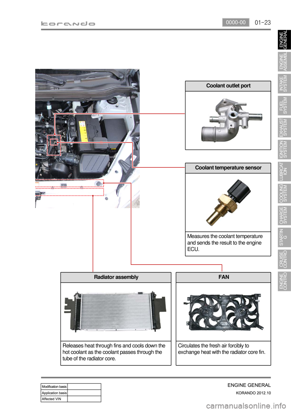
Coolant outlet port
Coolant temperature sensor
Measures the coolant temperature
and sends the result to the engine
ECU.
Radiator assembly
Releases heat through fins and cools down the
hot coolant as the coolant passes through the
tube of the radiator core.FAN
Circulates the fresh air forcibly to
exchange heat with the radiator core fin.
Page 348 of 1082
01-24
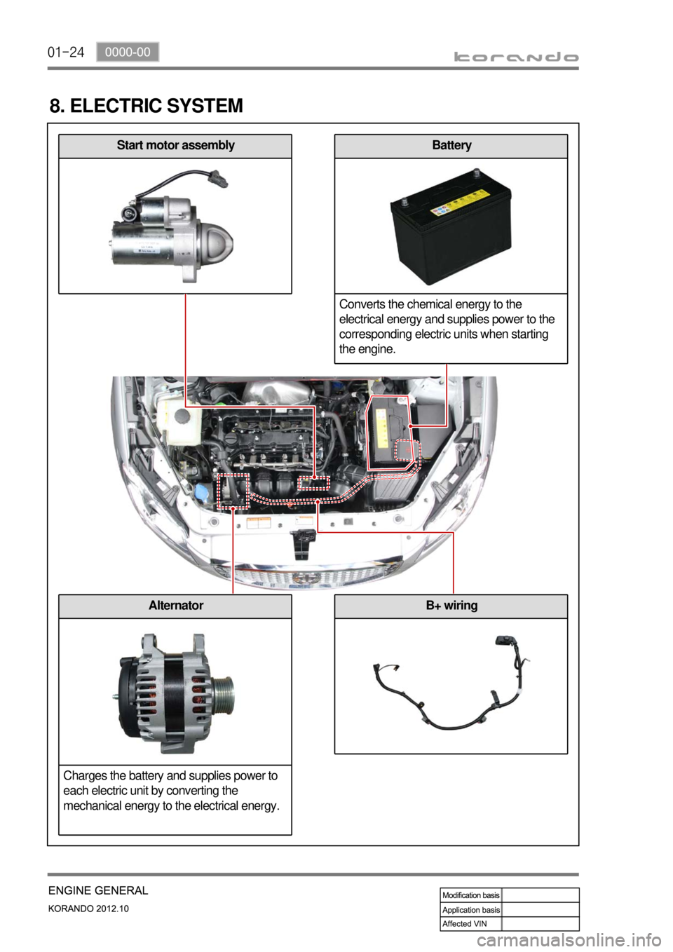
8. ELECTRIC SYSTEM
Start motor assemblyBattery
Converts the chemical energy to the
electrical energy and supplies power to the
corresponding electric units when starting
the engine.
B+ wiringAlternator
Charges the battery and supplies power to
each electric unit by converting the
mechanical energy to the electrical energy.
Page 351 of 1082

02-51116-01
Name Size Quantity Tightening torque
Intake manifold lower bracket bolt M8 X 1.25 X 16 425 ± 2.5 Nm
Exhaust manifold nut - 740 ± 5 Nm
Heat protector bolt M6 X 1.0 X 25 710 ± 1 Nm
Oil jet bolt - 410 ± 1 Nm
Oil pump bolt M8 X 1.25 X35 325 ± 2.5 Nm
Oil filter assembly assembly bolt M8 X 1.25 X30 325 ± 2.5 Nm
Oil filter assembly assembly bolt M8 X 1.25 X65 125 ± 2.5 Nm
Water pump bolt M6 X 1.0 X22 110 ± 1 Nm
Belt tensioner upper bolt M8 X 1.25 X30 125 ± 2.5 Nm
Belt tensioner lower bolt M10 X 1.5 X55 182 ± 5 Nm
Water pump pulley bolt M6 X 1.0 X12 410 ± 1 Nm
Thermostat bolt M6 X 1.0 X22 310 ± 1 Nm
Coolant outlet port bolt M6 X 1.0 X22 310 ± 1 Nm
Coolant pipe mounting bolt M6 X 1.0 X14 310 ± 1 Nm
Bypass hose clamp M24 23 ± 0.5 Nm
EPS idler pulley - 125 ± 2.5 Nm
Engine mountinf stud bolt - 250 ± 5.0 Nm
Engine front mounting bolt M10 X 45 360 ± 6.0 Nm
Engine front mounting bolt M10 X 77 160 ± 6.0 Nm
Engine front hanger bracket M8 X 1.25 X 20 225 ± 2.5 Nm
Engine rear hanger bracket M8 X 1.25 X 20 425 ± 2.5 Nm
A/C compressor bolt - 425 ± 2.5 Nm
Alternator bolt M10 445 ± 4.5 Nm
Start motor bolt M10 4 Max. 48Nm
Page 352 of 1082
02-6
3. GUIDELINES ON ENGINE SERVICE
G20DF engine is for FF (Front Engine Front Drive) type vehicle. Therefore, there are some deferent
maintenance and repair works compared to the engine for FR (Front Engine Rear Drive) type vehicle.
For safe and correct works, you must observe the working procedures and instructions in this manual.
And, use the designated tools as follow:
: Power train mounting stand / Engine hanger / Engine stand / Heavy duty engine jack.
Cautions before service works ▶
G20DF engine is FF (Front Engine Front Drive) type engine, and the engine and transmission are
integrated in a same module. Remember that there are many differences compared to
conventional engine in FR (Front Engine Rear Drive) type SUV vehicle.
To remove the engine, use the dedicated equipments such as engine jack, transmission jack,
engine stand and engine crane (1 ton).
To prevent the engine from abruptly starting during service in engine compartment, never allow
anybody to stay in the vehicle.
Make sure to disconnect the negative (-) cable from the battery to prevent any damage to electric
systems.
Make sure to clean the working area and to prepare the necessary tools before service works.
Always place the ignition switch to OFF position if not required. Otherwise, there could be
unexpected damage to electric devices or personal injuries due to short-circuit..
To prevent the foreign material from entering into the fuel injection system, completely seal the
inlets of HP pump, fuel hoses and high pressure pipes.
Do not remove the engine while supporting the oil pan with a jack. -
-
-
-
-
-
-
Lifting up the vehicle ▶
Before lifting up the vehicle with a lift, correctly support the lifting points.
To prevent the vehicle from rolling down, put the chocks under the tires (when using a 4-post lift).
Make sure to support the correct lifting points (when using a 2-post lift). -
-
-
