coolant SSANGYONG KORANDO 2012 User Guide
[x] Cancel search | Manufacturer: SSANGYONG, Model Year: 2012, Model line: KORANDO, Model: SSANGYONG KORANDO 2012Pages: 1082, PDF Size: 96.1 MB
Page 207 of 1082
08-4
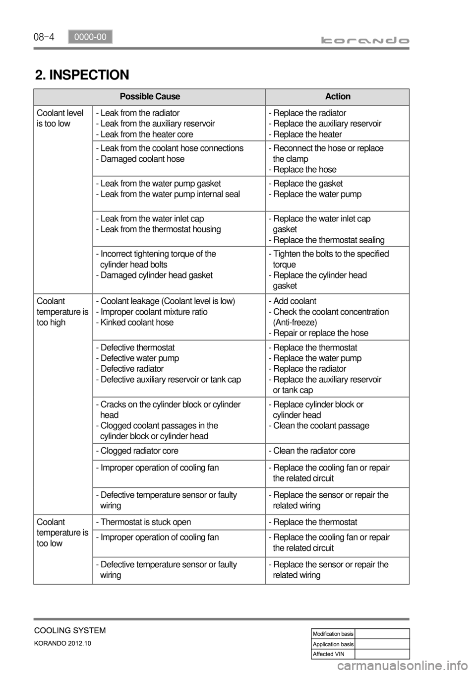
2. INSPECTION
Possible Cause Action
Coolant level
is too low- Leak from the radiator
- Leak from the auxiliary reservoir
- Leak from the heater core- Replace the radiator
- Replace the auxiliary reservoir
- Replace the heater
- Leak from the coolant hose connections
- Damaged coolant hose- Reconnect the hose or replace
the clamp
- Replace the hose
- Leak from the water pump gasket
- Leak from the water pump internal seal- Replace the gasket
- Replace the water pump
- Leak from the water inlet cap
- Leak from the thermostat housing- Replace the water inlet cap
gasket
- Replace the thermostat sealing
- Incorrect tightening torque of the
cylinder head bolts
- Damaged cylinder head gasket- Tighten the bolts to the specified
torque
- Replace the cylinder head
gasket
Coolant
temperature is
too high- Coolant leakage (Coolant level is low)
- Improper coolant mixture ratio
- Kinked coolant hose- Add coolant
- Check the coolant concentration
(Anti-freeze)
- Repair or replace the hose
- Defective thermostat
- Defective water pump
- Defective radiator
- Defective auxiliary reservoir or tank cap- Replace the thermostat
- Replace the water pump
- Replace the radiator
- Replace the auxiliary reservoir
or tank cap
- Cracks on the cylinder block or cylinder
head
- Clogged coolant passages in the
cylinder block or cylinder head- Replace cylinder block or
cylinder head
- Clean the coolant passage
- Clogged radiator core - Clean the radiator core
- Improper operation of cooling fan - Replace the cooling fan or repair
the related circuit
- Defective temperature sensor or faulty
wiring- Replace the sensor or repair the
related wiring
Coolant
temperature is
too low- Thermostat is stuck open - Replace the thermostat
- Improper operation of cooling fan - Replace the cooling fan or repair
the related circuit
- Defective temperature sensor or faulty
wiring- Replace the sensor or repair the
related wiring
Page 208 of 1082
08-50000-00
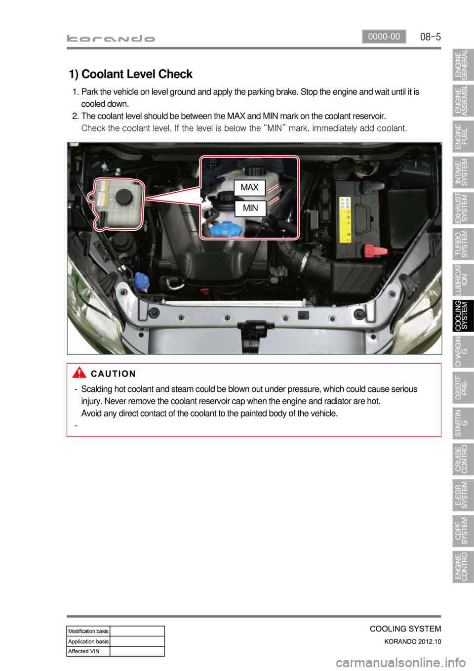
1) Coolant Level Check
Park the vehicle on level ground and apply the parking brake. Stop the engine and wait until it is
cooled down.
The coolant level should be between the MAX and MIN mark on the coolant reservoir.
Check the coolant level. If the level is below the “MIN” mark, immediately add coolant. 1.
2.
Scalding hot coolant and steam could be blown out under pressure, which could cause serious
injury. Never remove the coolant reservoir cap when the engine and radiator are hot.
Avoid any direct contact of the coolant to the painted body of the vehicle. -
-
MAX
MIN
Page 209 of 1082
08-6
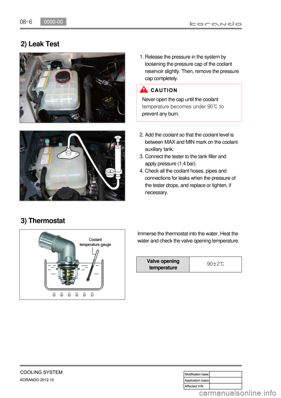
2) Leak Test
Release the pressure in the system by
loosening the pressure cap of the coolant
reservoir slightly. Then, remove the pressure
cap completely. 1.
Never open the cap until the coolant
temperature becomes under 90℃ to
prevent any burn.
Add the coolant so that the coolant level is
between MAX and MIN mark on the coolant
auxiliary tank.
Connect the tester to the tank filler and
apply pressure (1.4 bar).
Check all the coolant hoses, pipes and
connections for leaks when the pressure of
the tester drops, and replace or tighten, if
necessary. 2.
3.
4.
3) Thermostat
Immerse the thermostat into the water. Heat the
water and check the valve opening temperature.
Valve opening
temperature 90±2℃
Page 210 of 1082
08-70000-00
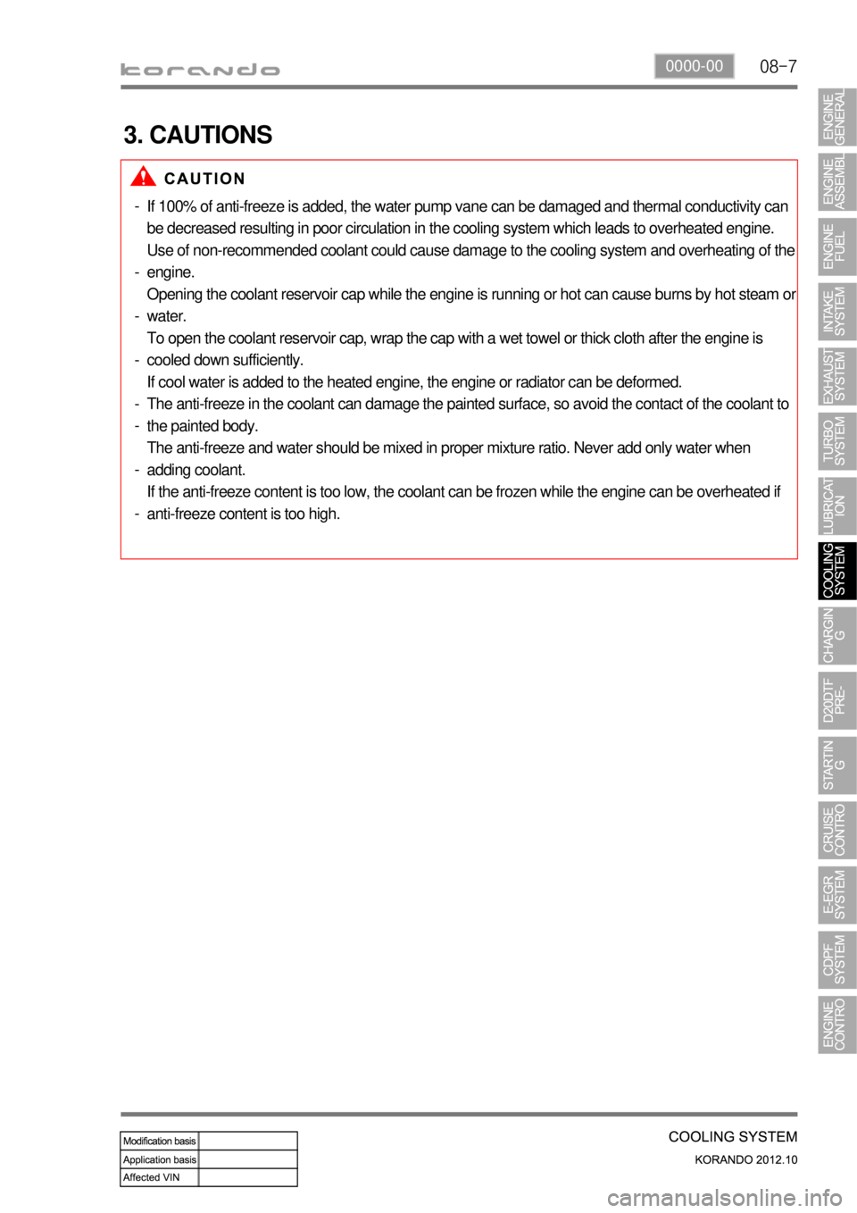
3. CAUTIONS
If 100% of anti-freeze is added, the water pump vane can be damaged and thermal conductivity can
be decreased resulting in poor circulation in the cooling system which leads to overheated engine.
Use of non-recommended coolant could cause damage to the cooling system and overheating of the
engine.
Opening the coolant reservoir cap while the engine is running or hot can cause burns by hot steam o
r
water.
To open the coolant reservoir cap, wrap the cap with a wet towel or thick cloth after the engine is
cooled down sufficiently.
If cool water is added to the heated engine, the engine or radiator can be deformed.
The anti-freeze in the coolant can damage the painted surface, so avoid the contact of the coolant to
the painted body.
The anti-freeze and water should be mixed in proper mixture ratio. Never add only water when
adding coolant.
If the anti-freeze content is too low, the coolant can be frozen while the engine can be overheated if
anti-freeze content is too high. -
-
-
-
-
-
-
-
Page 211 of 1082
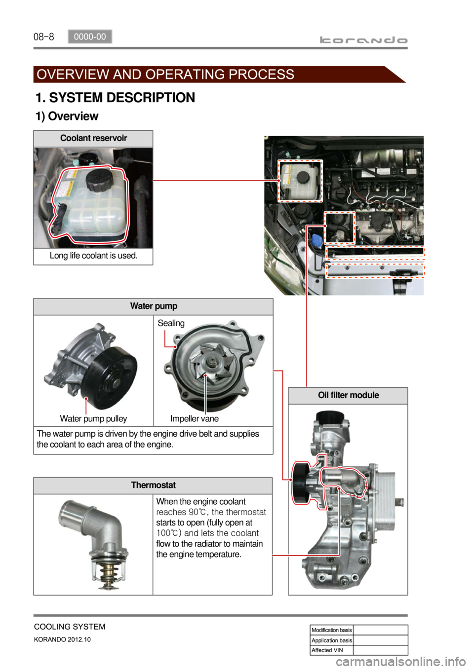
08-8
Thermostat
When the engine coolant
reaches 90℃, the thermostat
starts to open (fully open at
100℃) and lets the coolant
flow to the radiator to maintain
the engine temperature.
1. SYSTEM DESCRIPTION
1) Overview
Coolant reservoir
Long life coolant is used.
Water pump
The water pump is driven by the engine drive belt and supplies
the coolant to each area of the engine.
Oil filter module
Water pump pulley Impeller vaneSealing
Page 212 of 1082
08-90000-00
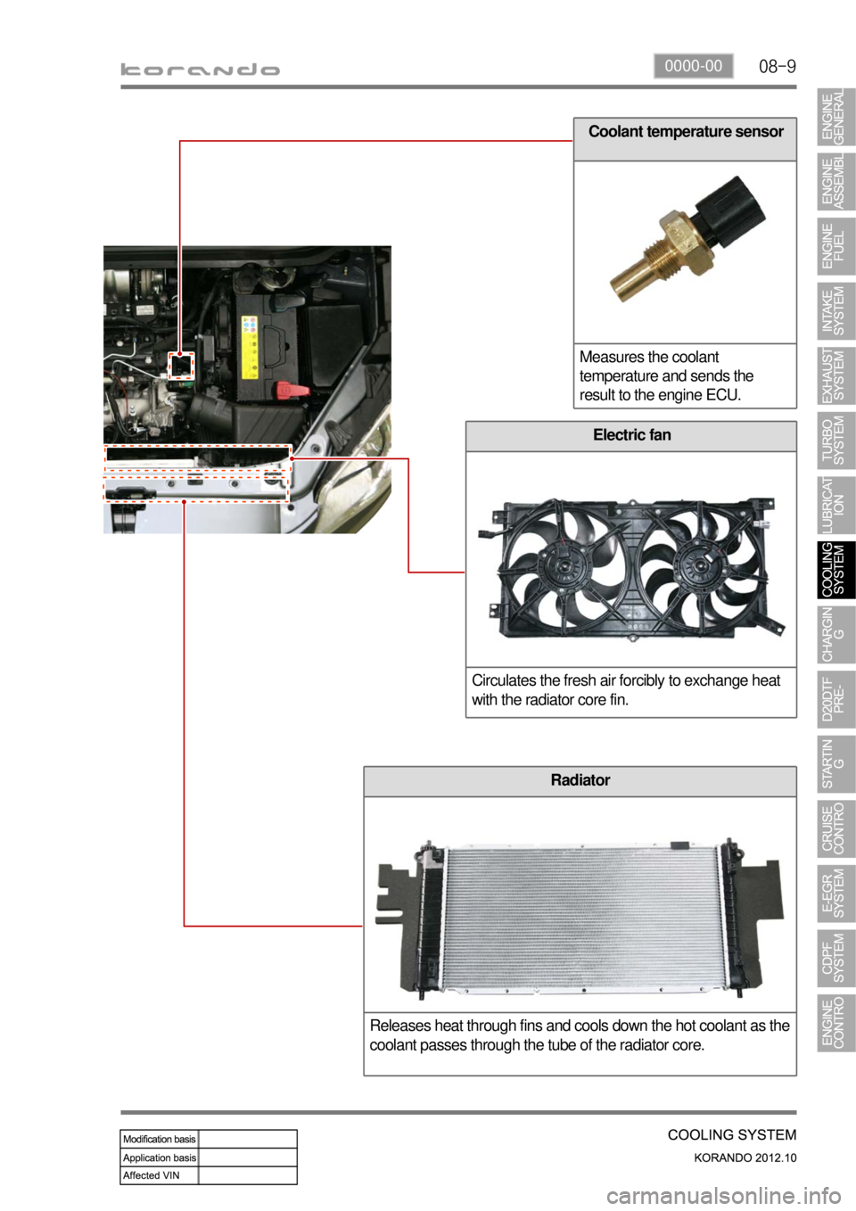
Coolant temperature sensor
Measures the coolant
temperature and sends the
result to the engine ECU.
Electric fan
Circulates the fresh air forcibly to exchange heat
with the radiator core fin.
Radiator
Releases heat through fins and cools down the hot coolant as the
coolant passes through the tube of the radiator core.
Page 229 of 1082
10-51413-00
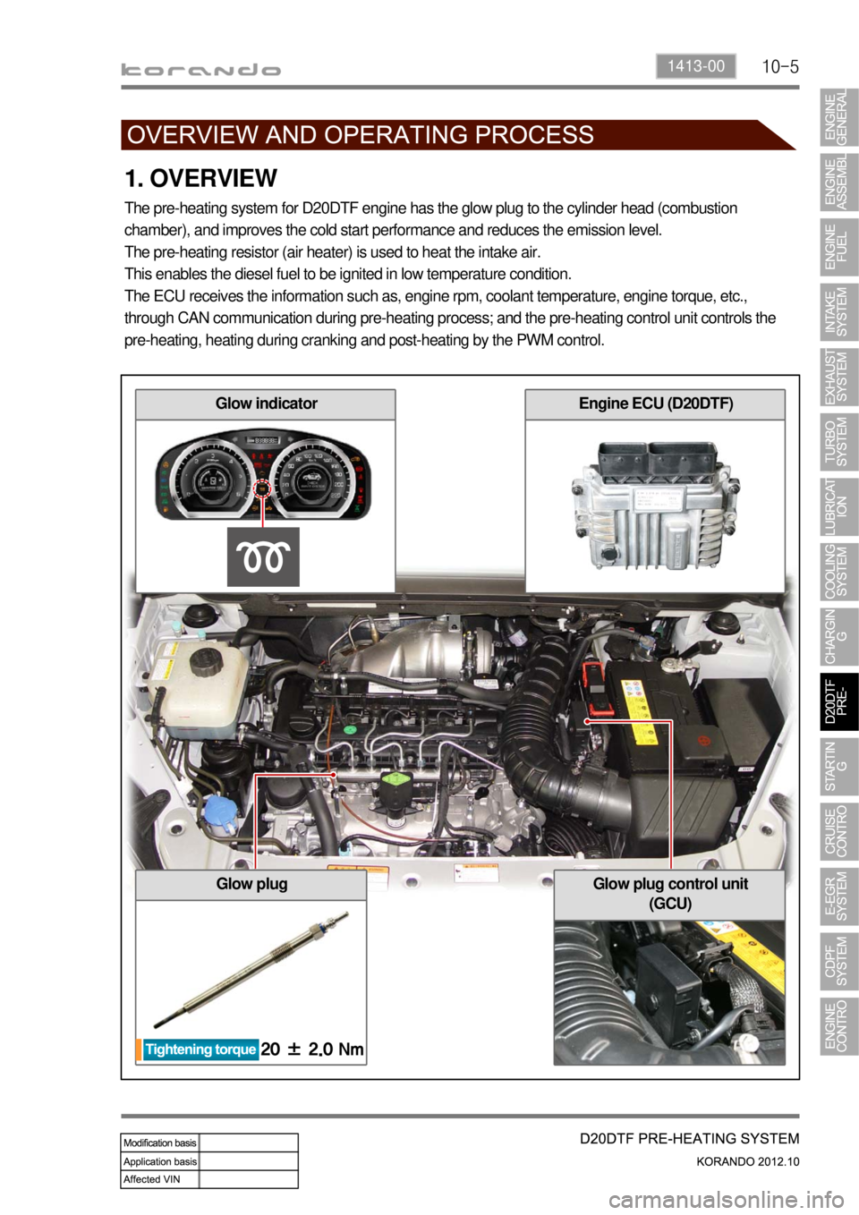
1. OVERVIEW
The pre-heating system for D20DTF engine has the glow plug to the cylinder head (combustion
chamber), and improves the cold start performance and reduces the emission level.
The pre-heating resistor (air heater) is used to heat the intake air.
This enables the diesel fuel to be ignited in low temperature condition.
The ECU receives the information such as, engine rpm, coolant temperature, engine torque, etc.,
through CAN communication during pre-heating process; and the pre-heating control unit controls the
pre-heating, heating during cranking and post-heating by the PWM control.
Glow plugGlow plug control unit
(GCU)
Glow indicatorEngine ECU (D20DTF)
Page 234 of 1082
10-10
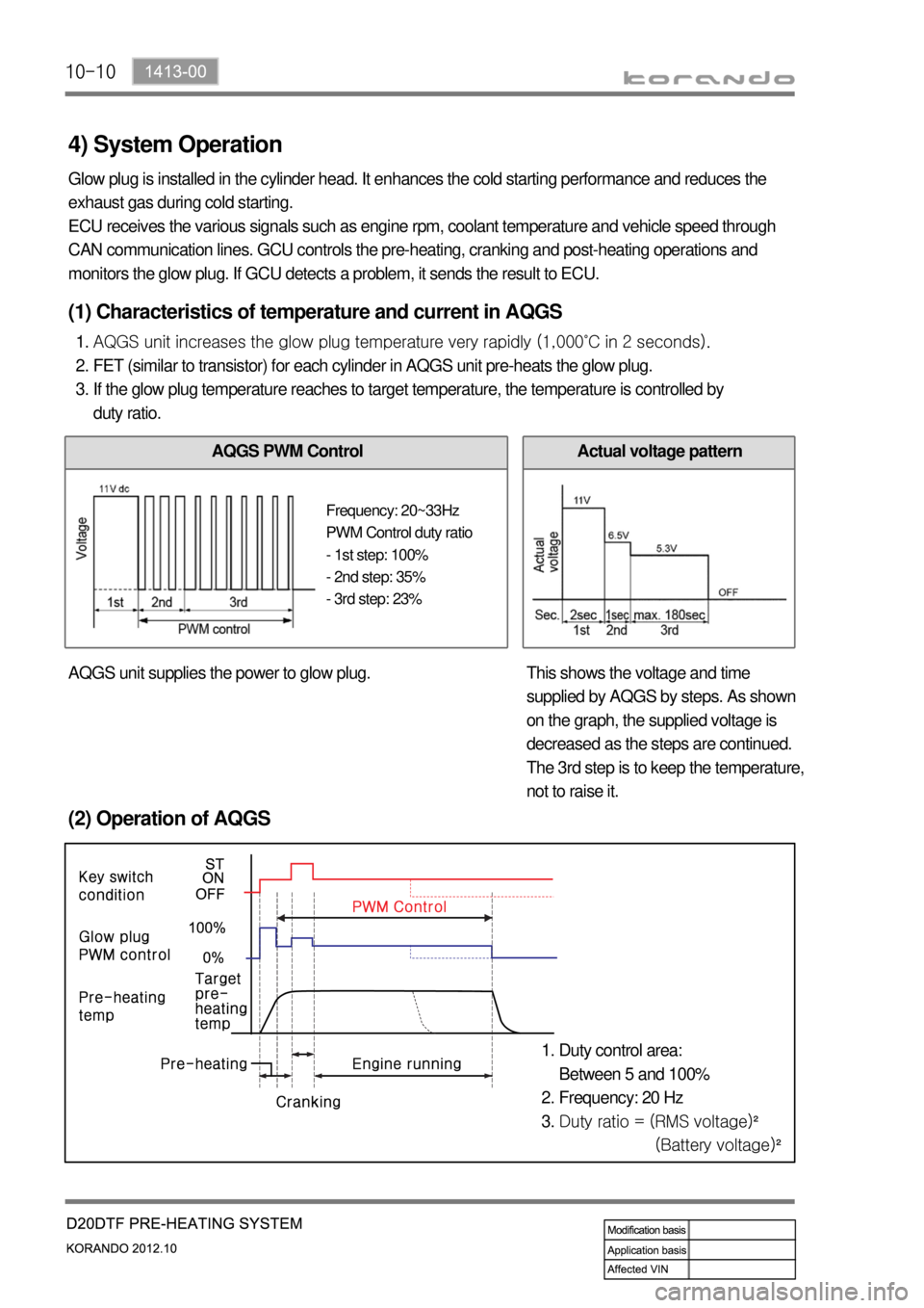
4) System Operation
Glow plug is installed in the cylinder head. It enhances the cold starting performance and reduces the
exhaust gas during cold starting.
ECU receives the various signals such as engine rpm, coolant temperature and vehicle speed through
CAN communication lines. GCU controls the pre-heating, cranking and post-heating operations and
monitors the glow plug. If GCU detects a problem, it sends the result to ECU.
(2) Operation of AQGS
Duty control area:
Between 5 and 100%
Frequency: 20 Hz
Duty ratio = (RMS voltage)²
(Battery voltage)² 1.
2.
3.
(1) Characteristics of temperature and current in AQGS
AQGS unit increases the glow plug temperature very rapidly (1,000˚C in 2 seconds).
FET (similar to transistor) for each cylinder in AQGS unit pre-heats the glow plug.
If the glow plug temperature reaches to target temperature, the temperature is controlled by
duty ratio. 1.
2.
3.
AQGS PWM ControlActual voltage pattern
AQGS unit supplies the power to glow plug. This shows the voltage and time
supplied by AQGS by steps. As shown
on the graph, the supplied voltage is
decreased as the steps are continued.
The 3rd step is to keep the temperature,
not to raise it.
Frequency: 20~33Hz
PWM Control duty ratio
- 1st step: 100%
- 2nd step: 35%
- 3rd step: 23%
Page 263 of 1082
13-51793-01
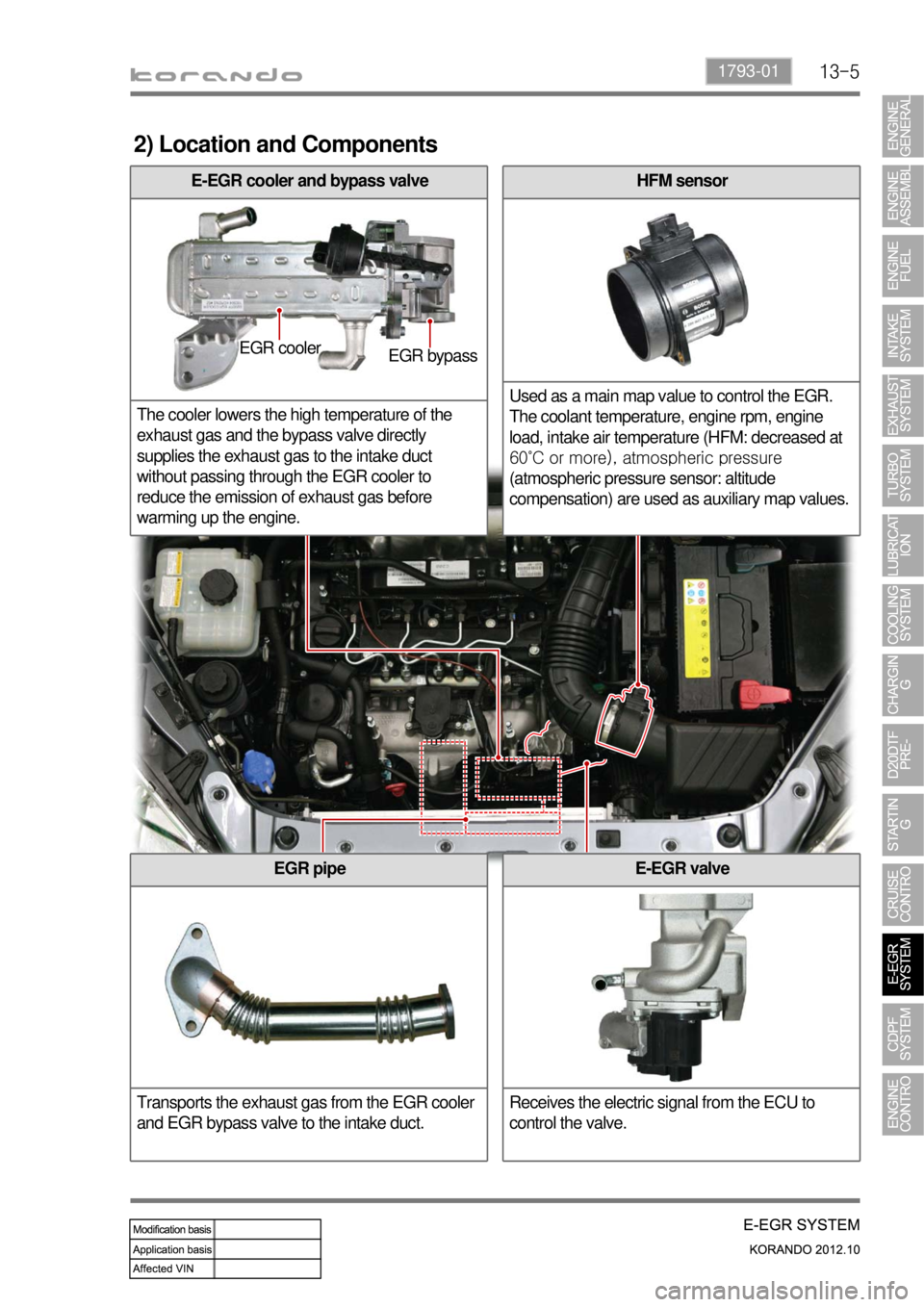
2) Location and Components
HFM sensor
Used as a main map value to control the EGR.
The coolant temperature, engine rpm, engine
load, intake air temperature (HFM: decreased at
60˚C or more), atmospheric pressure
(atmospheric pressure sensor: altitude
compensation) are used as auxiliary map values.
EGR pipe
Transports the exhaust gas from the EGR cooler
and EGR bypass valve to the intake duct.
E-EGR cooler and bypass valve
The cooler lowers the high temperature of the
exhaust gas and the bypass valve directly
supplies the exhaust gas to the intake duct
without passing through the EGR cooler to
reduce the emission of exhaust gas before
warming up the engine.
E-EGR valve
Receives the electric signal from the ECU to
control the valve.
EGR cooler
EGR bypass
Page 265 of 1082
13-71793-01
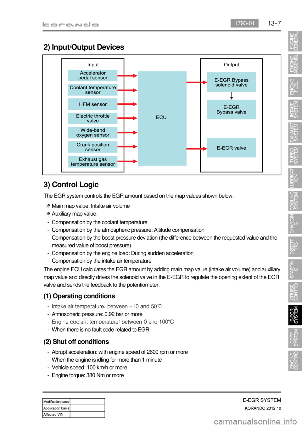
2) Input/Output Devices
3) Control Logic
The EGR system controls the EGR amount based on the map values shown below:
Main map value: Intake air volume
Auxiliary map value: ※
※
Compensation by the coolant temperature
Compensation by the atmospheric pressure: Altitude compensation
Compensation by the boost pressure deviation (the difference between the requested value and the
measured value of boost pressure)
Compensation by the engine load: During sudden acceleration
Compensation by the intake air temperature -
-
-
-
-
The engine ECU calculates the EGR amount by adding main map value (intake air volume) and auxiliary
map value and directly drives the solenoid valve in the E-EGR to regulate the opening extent of the EGR
valve and sends the feedback to the potentiometer.
(1) Operating conditions
Intake air temperature: between -10 and 50℃
Atmospheric pressure: 0.92 bar or more
Engine coolant temperature: between 0 and 100°C
When there is no fault code related to EGR -
-
-
-
(2) Shut off conditions
Abrupt acceleration: with engine speed of 2600 rpm or more
When the engine is idling for more than 1 minute
Vehicle speed: 100 km/h or more
Engine torque: 380 Nm or more -
-
-
-