coolant SSANGYONG KORANDO 2012 Service Manual
[x] Cancel search | Manufacturer: SSANGYONG, Model Year: 2012, Model line: KORANDO, Model: SSANGYONG KORANDO 2012Pages: 1082, PDF Size: 96.1 MB
Page 100 of 1082
01-4
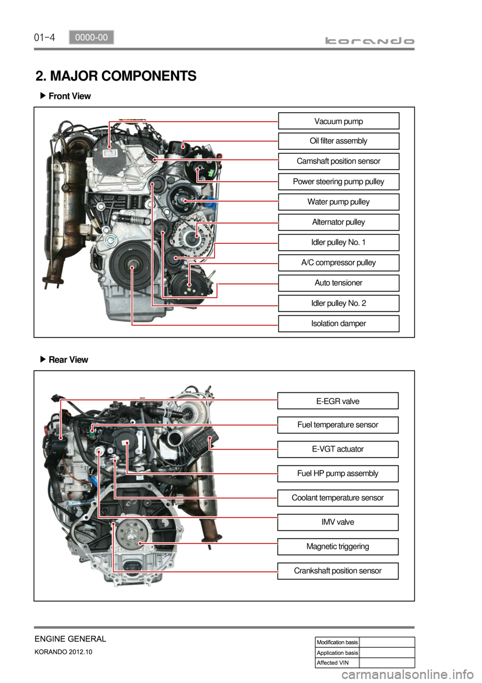
2. MAJOR COMPONENTS
Front View ▶
Vacuum pump
Oil filter assembly
Camshaft position sensor
Power steering pump pulley
Water pump pulley
Alternator pulley
Idler pulley No. 1
A/C compressor pulley
Auto tensioner
Idler pulley No. 2
Isolation damper
Rear View ▶
E-EGR valve
Fuel temperature sensor
Fuel HP pump assemblyE-VGT actuator
Coolant temperature sensor
IMV valve
Magnetic triggering
Crankshaft position sensor
Page 104 of 1082
01-8
4) Basic Inspection
(1) Horn operation
Listen for the horn sound when pressing the horn pad on the steering wheel. -
(2) Brake operation
Check if there is any abnormal noise, unusually long braking distance, or uneven braking force. If the
brake warning lamp does not go out even after starting the engien or are flashing during driving,
have the brake system checked immediately.
Check the brake pipes and hoses for connection, oil leak, crack or interference after changing the
position of tires. When replacing the tires, check the brake disc for surface condition and wear.
Check the parking brake cable and brake operation. Shorten the checking interval if the parking
brake is used frequently. -
-
-
(3) Exhaust system
Be aware to any changes in sound or smell from the exhaust system. These may be caused by leak or
overheat. Have the exhaust system checked and repaired immediately.
Inspect the exhaust system including catalytic converter. Inspect all the components and body frame
near the exhaust system. -
-
(4) Tires
Unusual vibration of the steering wheel and seats or pulling to one side on the straight and level roads
may indicates the uneven tire inflation pressure or poor wheel balance. -
(5) Steering and suspension system
Inspect the front and rear suspension and the steering system for damage, looseness or missing
parts, signs of wear or lack of lubrication. Inspect the power steering line and the hoses for
connection, leak, crack and chafing. Inspect the drive axle boot and seals for damage, tear or leak.
Replace or repair the system if necessary. -
(6) Engine oil
Check the oil level when the engine is still warm and add the specified engine oil if necessary. -
(7) Coolant
Check the coolant level in the coolant reservoir, coolant conditions (contamination, foreign material),
and hoses for damage and leak. Replace or add the Ssangyong genuine coolant, if needed. -
(8) Engine drive belt
Check all drive belts on the engine for wear, crack and looseness. Retighten or replace the belt, if
needed. -
Page 105 of 1082
01-90000-00
5) Guidelines on Engine Service
(1) Cautions before service works
Make sure to disconnect the negative (-) cable from the battery to prevent any damage to electric
systems.
Make sure to clean the working area and to prepare the necessary tools before service works.
Always place the ignition switch to OFF position if not required. Otherwise, there could be
unexpected damage to electric devices or personal injuries due to short-circuit.
To prevent the foreign material from entering into the fuel injection system, completely seal the inlets
of HP pump, fuel hoses and high pressure pipes.
To remoev the engine, use the dedicated equipments such as engine jack, transmission jack, engine
stand and engine crane. -
-
-
-
-
(2) Engine and accessories
When disassembling the engine, related parts (bolts, gaskets, etc.) should be stored as a set.
Clean the components completely with engine oil before assembling if needed.
Fully drain the engine oil, coolant and fuel from the vehicle and seal the inlets with the plugs before
removing the engine.
All the interference should be eliminated before removing the engine. -
-
-
-
(3) Electric devices
To prevent any damage to electric systems, make sure to disconnect the negative (-) cable from the
battery and place the ignition switch to OFF position before servicing.
Use only the specified parts with same ratings when replacing the electric devices. Check the
grounds and connections for looseness. -
- To prevent the personal injuries and vehicle damages that can be caused by mistakes during service
and to provide the optimized performance and safety after service works, the service technicials must
keep the basic cautions and service guidelines below. These could be easily forgotten during service
works.
Engine has a lot of precise components. The specified tightening torque and correct procedures should
be kept during service works. And, the working area is always clean and well prepared.
Extraordinary care should be taken when servicing the electric systems. Currently, the engine uses a lot
of electric devices. Short circuit and poor contact may cause the low engine performance, incomplete
combustion and other abnormalities.
Page 111 of 1082
02-4
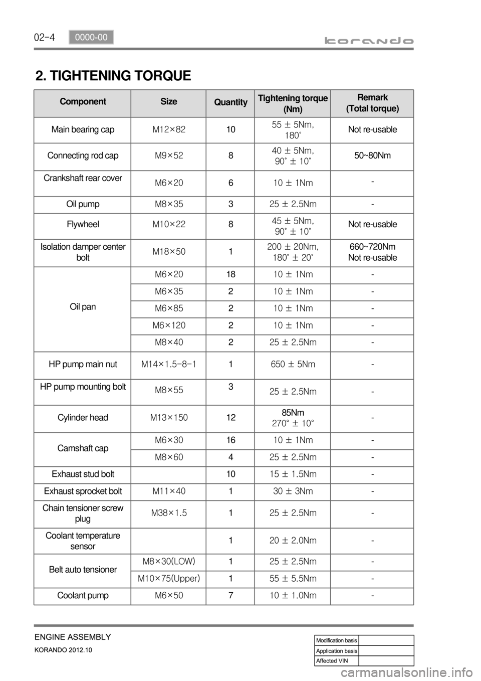
2. TIGHTENING TORQUE
Component Size
QuantityTightening torque
(Nm)Remark
(Total torque)
Main bearing capM12×821055 ± 5Nm,
180˚Not re-usable
Connecting rod capM9×52840 ± 5Nm,
90˚ ± 10˚50~80Nm
Crankshaft rear cover
M6×20610 ± 1Nm-
Oil pumpM8×35325 ± 2.5Nm-
FlywheelM10×22845 ± 5Nm,
90˚ ± 10˚Not re-usable
Isolation damper center
boltM18×501200 ± 20Nm,
180˚ ± 20˚660~720Nm
Not re-usable
Oil panM6×201810 ± 1Nm-
M6×35210 ± 1Nm-
M6×85210 ± 1Nm-
M6×120210 ± 1Nm-
M8×40225 ± 2.5Nm-
HP pump main nutM14×1.5-8-11650 ± 5Nm-
HP pump mounting bolt
M8×553
25 ± 2.5Nm-
Cylinder headM13×1501285Nm
270° ± 10°-
Camshaft capM6×301610 ± 1Nm-
M8×60425 ± 2.5Nm-
Exhaust stud bolt 1015 ± 1.5Nm-
Exhaust sprocket boltM11×40130 ± 3Nm-
Chain tensioner screw
plugM38×1.5125 ± 2.5Nm
-
Coolant temperature
sensor120 ± 2.0Nm-
Belt auto tensionerM8×30(LOW)125 ± 2.5Nm-
M10×75(Upper)155 ± 5.5Nm-
Coolant pumpM6×50710 ± 1.0Nm-
Page 121 of 1082
02-14
4. GUIDELINES ON ENGINE SERVICE
To prevent personal injuries and vehicle damages that can be caused by mistakes during engine and
unit inspection/repair and to secure optimum engine performance and safety after service works, basic
cautions and service work guidelines that can be easily forgotten during engine service works are
described in.
Cautions before service works
For safe and correct works, you must observe the working procedures and instructions in this
manual. And, use the designated tools as follow:
Engine stand / Heavy duty engine jack
To prevent the engine from starting abruptly, do not allow anybody to get in the vehicle while
servicing in engine compartment.
Before work on engine and each electrical equipment, be sure to disconnect battery negative (-)
terminal.
Before service works, be sure to prepare the works by cleaning and aligning work areas.
Do not allow the foreign material get into the fuel injection system.
When removing the engine, use only the safety hook on engine and engine hanger. Do not support
the bottom of oil pan with a jack.
Engine and accessories ▶
-
-
-
-
-
-
▶
Completely drain the engine oil, coolant and fuel from engine before removal.
Before disassembling/assembling the engine components, carefully read the working procedures in
this manual.
Make sure to keep the specified tightening torques during installation.
Clean and properly lubricate the parts before reassembly.
Carefully check that there are not any interference while servicing. -
-
-
-
- Engine has a lot of precise portions so tightening torque should be correct during disassembly/assembly
and removal/installation and service work should be done in clean ways during disassembly/assembly.
Maintaining working area clean and cautious service administration is essential element of service works
while working on the engine and each section of the vehicle. So the mechanics should well aware of it.
Page 152 of 1082
03-170000-00
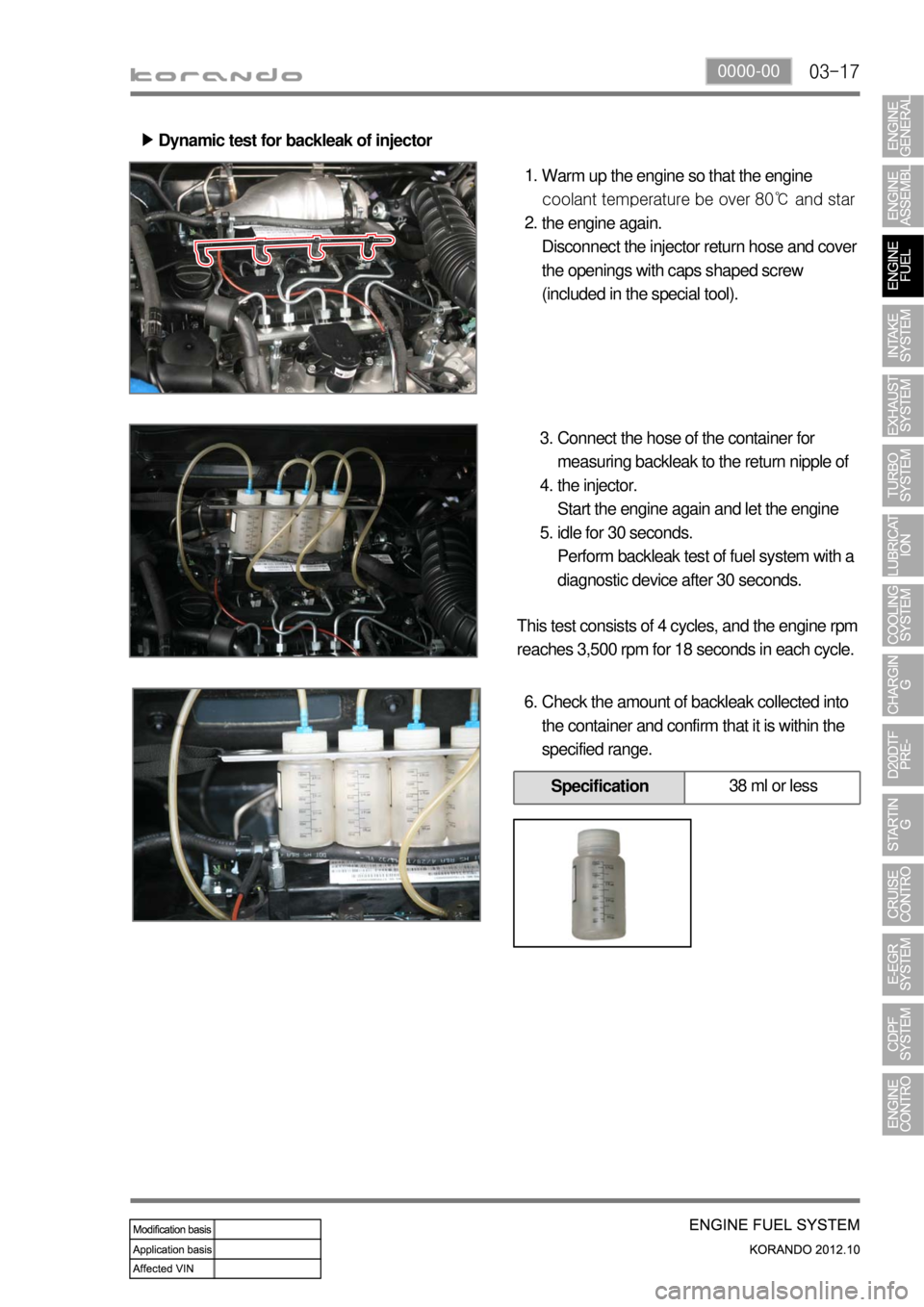
Dynamic test for backleak of injector ▶
Warm up the engine so that the engine
coolant temperature be over 80℃ and star
the engine again.
Disconnect the injector return hose and cover
the openings with caps shaped screw
(included in the special tool). 1.
2.
Connect the hose of the container for
measuring backleak to the return nipple of
the injector.
Start the engine again and let the engine
idle for 30 seconds.
Perform backleak test of fuel system with a
diagnostic device after 30 seconds. 3.
4.
5.
This test consists of 4 cycles, and the engine rpm
reaches 3,500 rpm for 18 seconds in each cycle.
Check the amount of backleak collected into
the container and confirm that it is within the
specified range. 6.
Specification38 ml or less
Page 163 of 1082
03-28
The engine ECU calculates the accelerator pedal based on the input signals from various sensors, and
controls the overall operation of the vehicle.
The ECU receives the signals from various sensor through data line, and performs effective air-fuel ratio
control based on these signals.
The crankshaft speed (position) sensor measures the engine speed, and the camshaft speed (position)
sensor determines the order of injections, and the ECU detects the amount of the accelerator pedal
depressed (driver's will) by receiving the electrical signals from the accelerator pedal sensor.
The mass air flow sensor detects the volume of intake air and sends the value to the ECU.
The major function of the ECU is controlling air-fuel ratio to reduce the emission level (EGR valve control)
by detecting instantaneous air flow change with the signals from the mass air flow sensor.
Also, the ECU uses the signals from the coolant temperature & air temperature sensors, booster pressure
sensor, atmospheric pressure sensor to: a) determine injection starting point and set value for pilot
injection, and b) deal with various operations and variable conditions.
Page 196 of 1082
06-190000-00
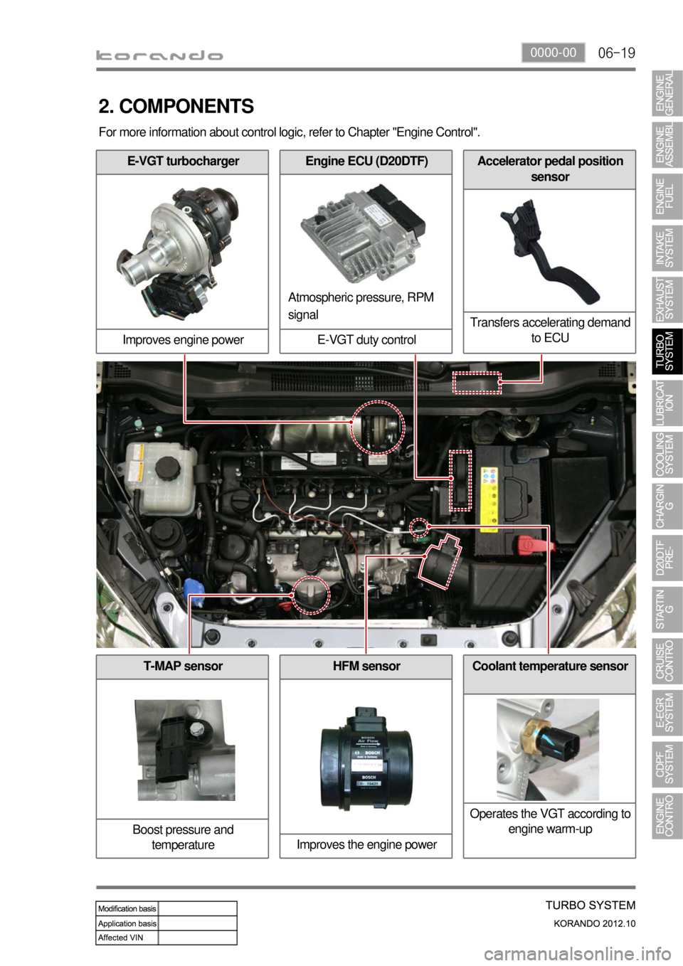
T-MAP sensor
Boost pressure and
temperature
E-VGT turbocharger
Improves engine power
2. COMPONENTS
Engine ECU (D20DTF)
E-VGT duty controlAccelerator pedal position
sensor
Transfers accelerating demand
to ECU
Atmospheric pressure, RPM
signal
HFM sensor
Improves the engine powerCoolant temperature sensor
Operates the VGT according to
engine warm-up
For more information about control logic, refer to Chapter "Engine Control".
Page 203 of 1082
07-6
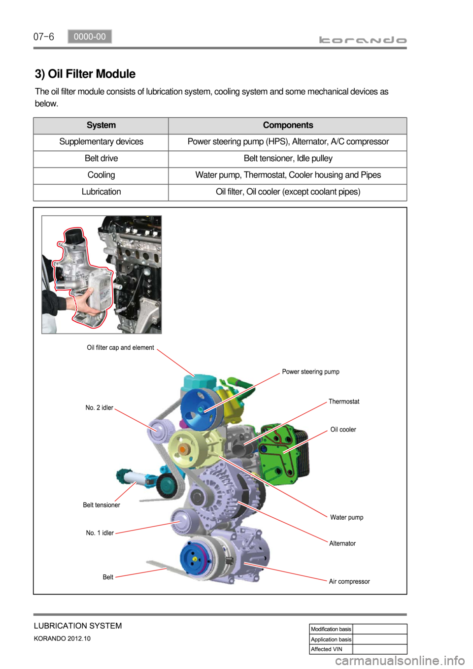
3) Oil Filter Module
The oil filter module consists of lubrication system, cooling system and some mechanical devices as
below.
System Components
Supplementary devices Power steering pump (HPS), Alternator, A/C compressor
Belt drive Belt tensioner, Idle pulley
Cooling Water pump, Thermostat, Cooler housing and Pipes
Lubrication Oil filter, Oil cooler (except coolant pipes)
Page 206 of 1082
08-30000-00
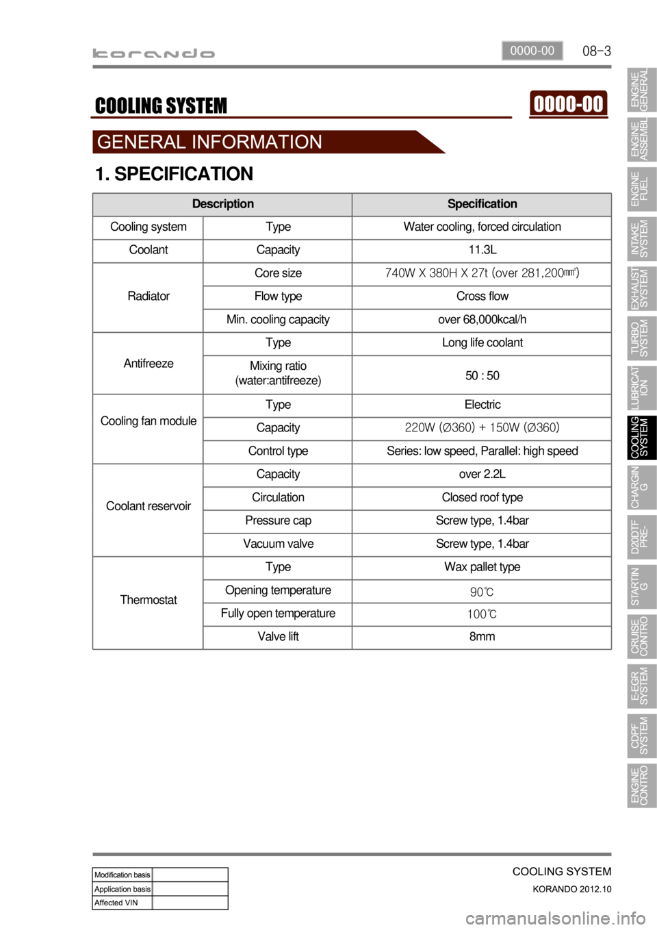
1. SPECIFICATION
Description Specification
Cooling system Type Water cooling, forced circulation
Coolant Capacity 11.3L
RadiatorCore size740W X 380H X 27t (over 281,200㎣)
Flow type Cross flow
Min. cooling capacity over 68,000kcal/h
AntifreezeType Long life coolant
Mixing ratio
(water:antifreeze)50 : 50
Cooling fan moduleType Electric
Capacity220W (Ø360) + 150W (Ø360)
Control type Series: low speed, Parallel: high speed
Coolant reservoirCapacity over 2.2L
Circulation Closed roof type
Pressure cap Screw type, 1.4bar
Vacuum valve Screw type, 1.4bar
ThermostatType Wax pallet type
Opening temperature
90℃
Fully open temperature
100℃
Valve lift 8mm