oil SSANGYONG KORANDO 2012 User Guide
[x] Cancel search | Manufacturer: SSANGYONG, Model Year: 2012, Model line: KORANDO, Model: SSANGYONG KORANDO 2012Pages: 1082, PDF Size: 96.1 MB
Page 121 of 1082
02-14
4. GUIDELINES ON ENGINE SERVICE
To prevent personal injuries and vehicle damages that can be caused by mistakes during engine and
unit inspection/repair and to secure optimum engine performance and safety after service works, basic
cautions and service work guidelines that can be easily forgotten during engine service works are
described in.
Cautions before service works
For safe and correct works, you must observe the working procedures and instructions in this
manual. And, use the designated tools as follow:
Engine stand / Heavy duty engine jack
To prevent the engine from starting abruptly, do not allow anybody to get in the vehicle while
servicing in engine compartment.
Before work on engine and each electrical equipment, be sure to disconnect battery negative (-)
terminal.
Before service works, be sure to prepare the works by cleaning and aligning work areas.
Do not allow the foreign material get into the fuel injection system.
When removing the engine, use only the safety hook on engine and engine hanger. Do not support
the bottom of oil pan with a jack.
Engine and accessories ▶
-
-
-
-
-
-
▶
Completely drain the engine oil, coolant and fuel from engine before removal.
Before disassembling/assembling the engine components, carefully read the working procedures in
this manual.
Make sure to keep the specified tightening torques during installation.
Clean and properly lubricate the parts before reassembly.
Carefully check that there are not any interference while servicing. -
-
-
-
- Engine has a lot of precise portions so tightening torque should be correct during disassembly/assembly
and removal/installation and service work should be done in clean ways during disassembly/assembly.
Maintaining working area clean and cautious service administration is essential element of service works
while working on the engine and each section of the vehicle. So the mechanics should well aware of it.
Page 122 of 1082
02-150000-00
Electrical equipment ▶
Electric devices should be handled more carefully.
Currently, the engine has a lot of electric devices. there could be poor engine performance, incomplete
combustion and other abnormal symptoms due to short circuit or poor contact.
Before work on engine and each electrical equipment, be sure to disconnect battery negative (-)
terminal.
When replacing the electric device, use only genuine part and check the conditions of connections
and grounds. Loosened connection or ground make cause a fire and personal injury. -
-Fuel and lubrication system ▶
Do not allow the fluid and engine oil to make contact with the body paintwork and hoses.
If work on the fluid system such as fuel and oil, working area should be well ventilated and smoking
should be prohibited.
Gasket or seal on the fuel/lubrication system should be replaced with new ones and bolts and nuts
should be tightened as specified.
After removal/installation works, be sure to check whether there is leak on the connecting section. -
-
-
-
If fine dust or foreign material enters into DI engine's fuel system, there can be serious damages in HP
pump and injectors. Thus, be sure to plug the inlets of removed fuel line components with cap and
protect removed parts not to be contaminated with dirt. (Refer to cleanness in this manual while working
on DI engine fuel system)
Page 123 of 1082
02-16
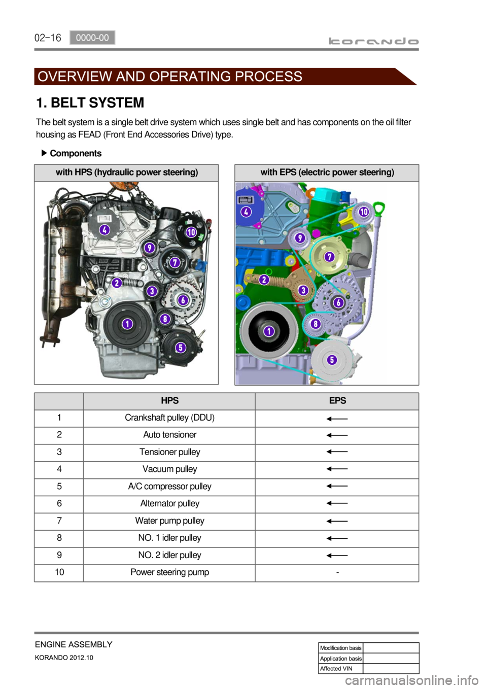
with EPS (electric power steering)
1. BELT SYSTEM
The belt system is a single belt drive system which uses single belt and has components on the oil filter
housing as FEAD (Front End Accessories Drive) type.
Components ▶
HPS EPS
1 Crankshaft pulley (DDU)
2 Auto tensioner
3 Tensioner pulley
4 Vacuum pulley
5 A/C compressor pulley
6 Alternator pulley
7 Water pump pulley
8 NO. 1 idler pulley
9 NO. 2 idler pulley
10 Power steering pump -
with HPS (hydraulic power steering)
Page 124 of 1082
02-170000-00
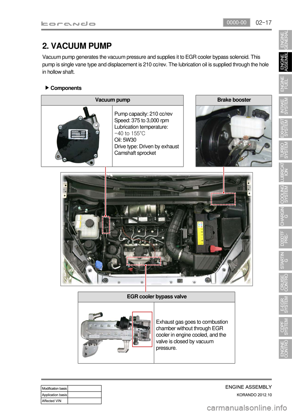
EGR cooler bypass valve
Exhaust gas goes to combustion
chamber without through EGR
cooler in engine cooled, and the
valve is closed by vacuum
pressure.
2. VACUUM PUMP
Vacuum pump generates the vacuum pressure and supplies it to EGR cooler bypass solenoid. This
pump is single vane type and displacement is 210 cc/rev. The lubrication oil is supplied through the hole
in hollow shaft.
Components ▶
Vacuum pump
Pump capacity: 210 cc/rev
Speed: 375 to 3,000 rpm
Lubrication temperature:
-40 to 155°C
Oil: 5W30
Drive type: Driven by exhaust
Camshaft sprocketBrake booster
Page 127 of 1082
02-20
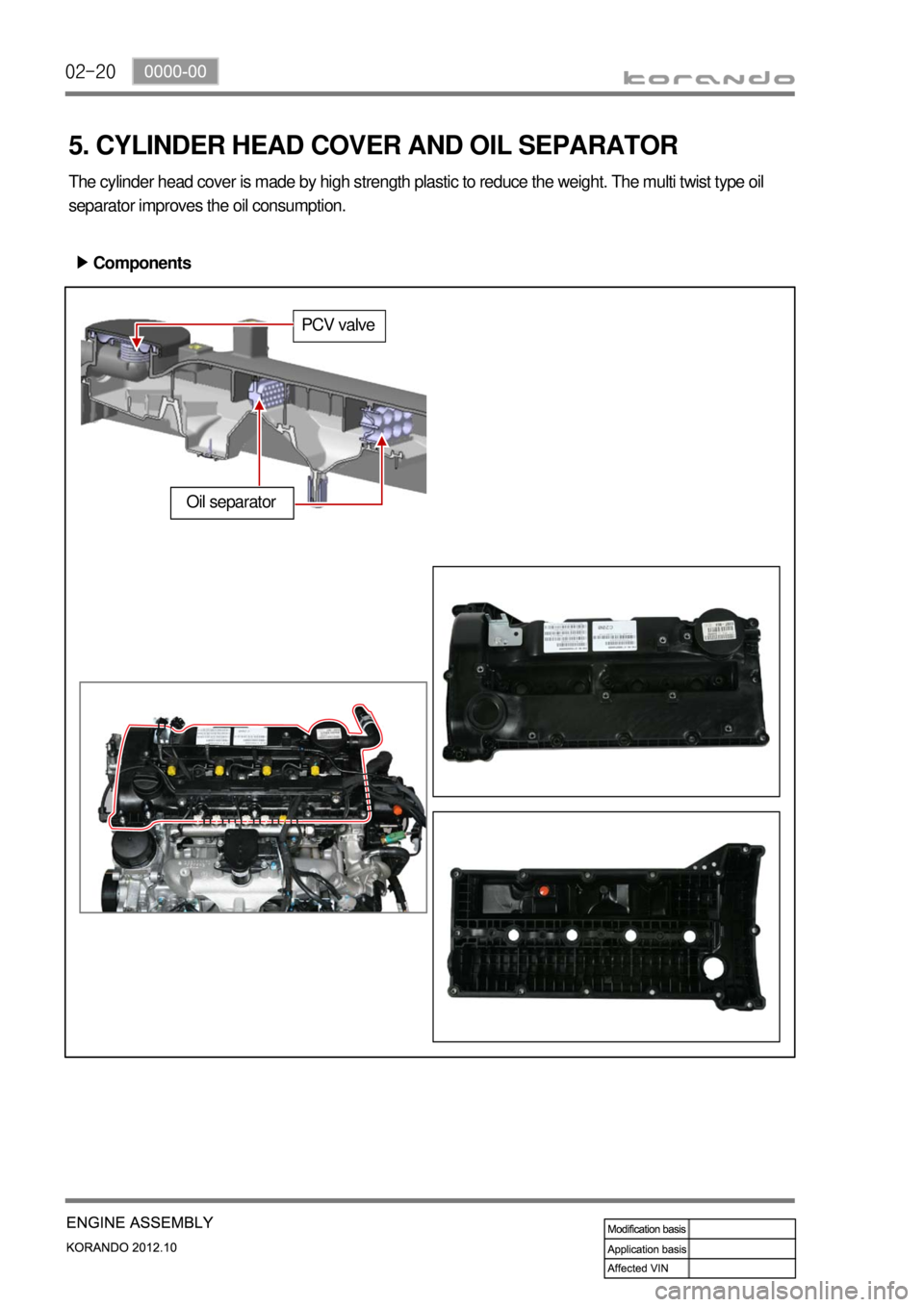
5. CYLINDER HEAD COVER AND OIL SEPARATOR
The cylinder head cover is made by high strength plastic to reduce the weight. The multi twist type oil
separator improves the oil consumption.
Components ▶
Oil separator
PCV valve
Page 130 of 1082
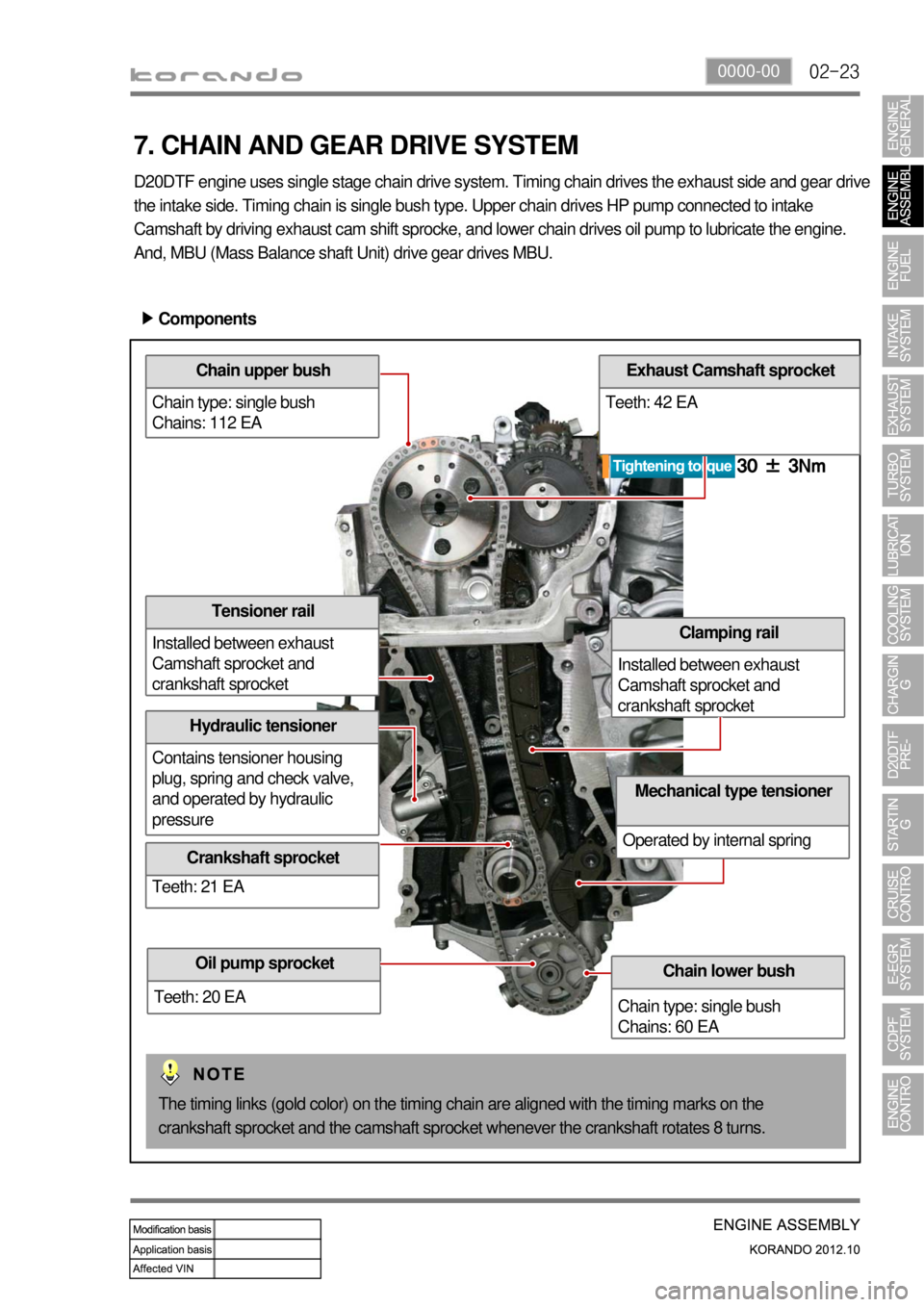
02-230000-00
Chain upper bush
Chain type: single bush
Chains: 112 EA
Tensioner rail
Installed between exhaust
Camshaft sprocket and
crankshaft sprocket
Hydraulic tensioner
Contains tensioner housing
plug, spring and check valve,
and operated by hydraulic
pressure
Crankshaft sprocket
Teeth: 21 EA
Exhaust Camshaft sprocket
Teeth: 42 EA
Clamping rail
Installed between exhaust
Camshaft sprocket and
crankshaft sprocket
7. CHAIN AND GEAR DRIVE SYSTEM
D20DTF engine uses single stage chain drive system. Timing chain drives the exhaust side and gear drive
the intake side. Timing chain is single bush type. Upper chain drives HP pump connected to intake
Camshaft by driving exhaust cam shift sprocke, and lower chain drives oil pump to lubricate the engine.
And, MBU (Mass Balance shaft Unit) drive gear drives MBU.
Components ▶
Chain lower bush
Chain type: single bush
Chains: 60 EAOil pump sprocket
Teeth: 20 EA
Mechanical type tensioner
Operated by internal spring
The timing links (gold color) on the timing chain are aligned with the timing marks on the
crankshaft sprocket and the camshaft sprocket whenever the crankshaft rotates 8 turns.
Page 132 of 1082
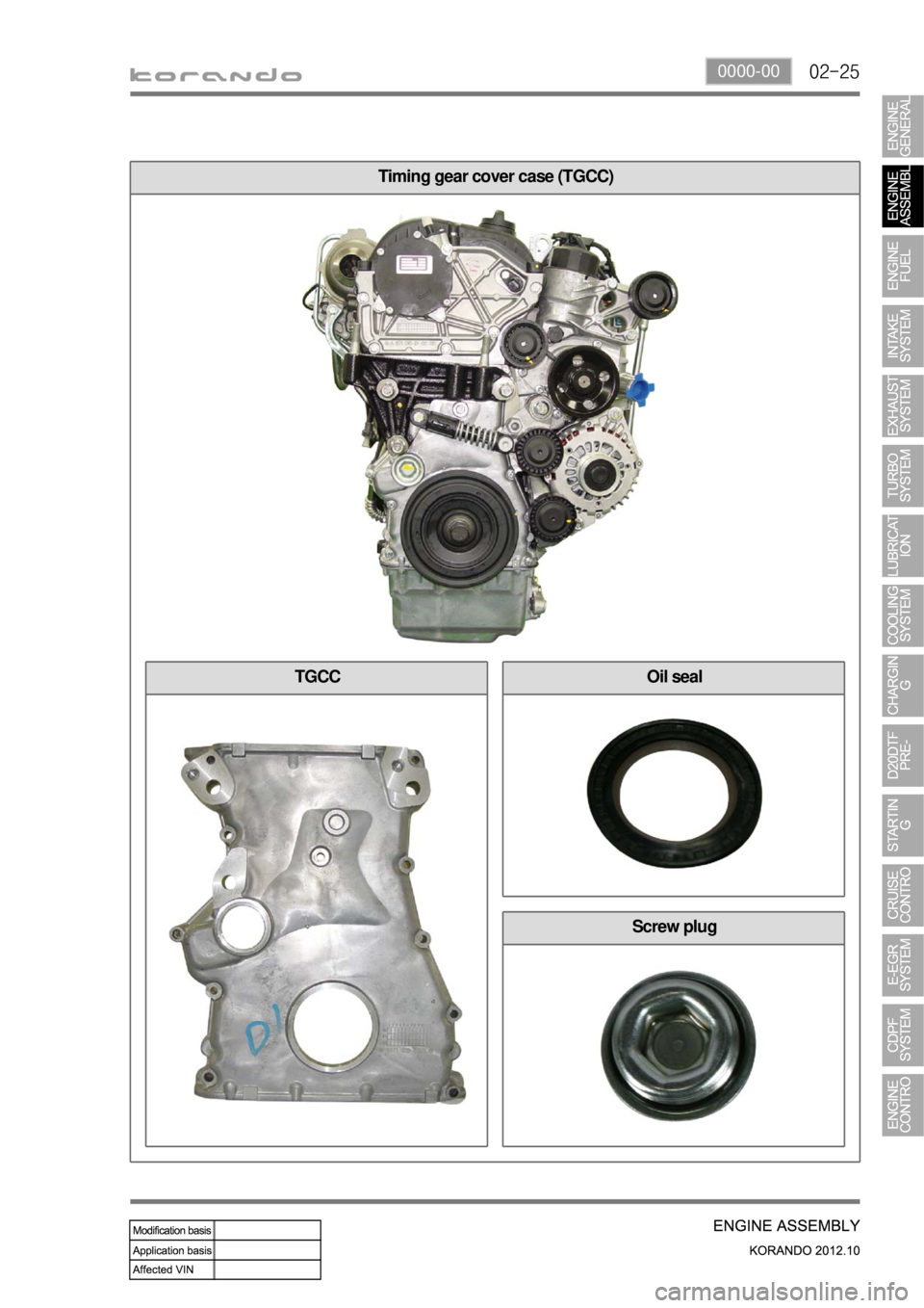
02-250000-00
Timing gear cover case (TGCC)
TGCCOil seal
Screw plug
Page 134 of 1082
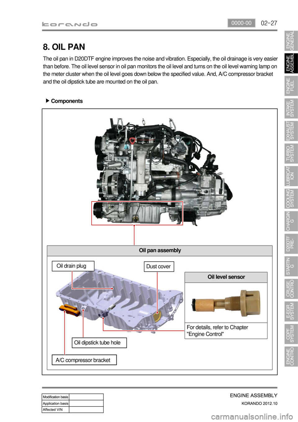
02-270000-00
Oil pan assembly
8. OIL PAN
The oil pan in D20DTF engine improves the noise and vibration. Especially, the oil drainage is very easier
than before. The oil level sensor in oil pan monitors the oil level and turns on the oil level warning lamp on
the meter cluster when the oil level goes down below the specified value. And, A/C compressor bracket
and the oil dipstick tube are mounted on the oil pan.
Components ▶
Oil drain plugDust cover
Oil dipstick tube hole
A/C compressor bracket
Oil level sensor
For details, refer to Chapter
"Engine Control"
Page 139 of 1082
03-4
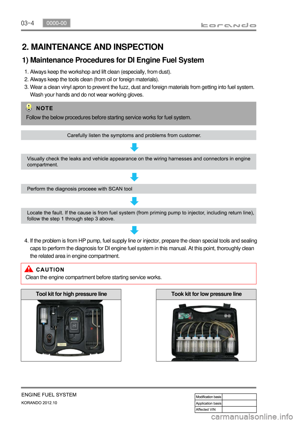
2. MAINTENANCE AND INSPECTION
1) Maintenance Procedures for DI Engine Fuel System
Always keep the workshop and lift clean (especially, from dust).
Always keep the tools clean (from oil or foreign materials).
Wear a clean vinyl apron to prevent the fuzz, dust and foreign materials from getting into fuel system.
Wash your hands and do not wear working gloves. 1.
2.
3.
Follow the below procedures before starting service works for fuel system.
If the problem is from HP pump, fuel supply line or injector, prepare the clean special tools and sealing
caps to perform the diagnosis for DI engine fuel system in this manual. At this point, thoroughly clean
the related area in engine compartment. 4.
Clean the engine compartment before starting service works.
Tool kit for high pressure lineTook kit for low pressure line
Page 157 of 1082
03-22
(2) Di engine and its expected problems and remedies can be caused by
water in fuel
System supplement against paraffin separation ▶
In case of Diesel fuel, paraffin, one of the elements, can be separated from fuel during winter and then
can stick on the fuel filter blocking fuel flow and causing difficult starting finally. Oil companies supply
summer fuel and winter fuel by differentiating mixing ratio of kerosene and other elements by region and
season. However, above phenomenon can be happened if stations have poor facilities or sell improper
fuel for the season. In case of DI engine, purity of fuel is very important factor to keep internal
preciseness of HP pump and injector.
Accordingly, more dense mesh than conventional fuel filter is used. To prevent fuel filter internal clogging
due to paraffin separation, SYMC is using fuel line that high pressure and temperature fuel injected by
injector returns through fuel filter to have an effect of built-in heater (see fuel system).
System supplement and remedy against water in fuel ▶
As mentioned above, some gas stations supply fuel with excessive than specified water. In the
conventional IDI engine, excessive water in the fuel only causes dropping engine power or engine
hunting. However, fuel system in the DI engine consists of precise components so water in the fuel can
cause malfunctions of HP pump due to poor lubrication of pump caused by poor coating film during high
speed pumping and bacterization (under long period parking). To prevent problems can be caused by
excessive water in fuel, water separator is installed inside of fuel filter. When fuel is passing filter, water
that has relatively bigger specific gravity is accumulated on the bottom of the filter.
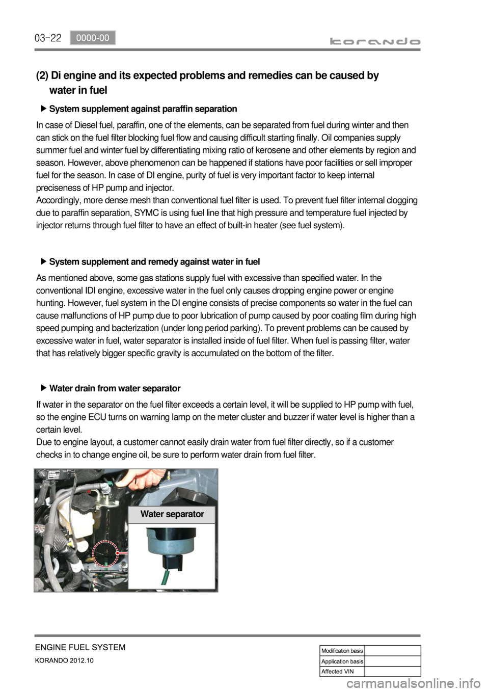
Water drain from water separator ▶
If water in the separator on the fuel filter exceeds a certain level, it will be supplied to HP pump with fuel,
so the engine ECU turns on warning lamp on the meter cluster and buzzer if water level is higher than a
certain level.
Due to engine layout, a customer cannot easily drain water from fuel filter directly, so if a customer
checks in to change engine oil, be sure to perform water drain from fuel filter.
Water separator