transmission SSANGYONG KORANDO 2012 User Guide
[x] Cancel search | Manufacturer: SSANGYONG, Model Year: 2012, Model line: KORANDO, Model: SSANGYONG KORANDO 2012Pages: 1082, PDF Size: 96.1 MB
Page 661 of 1082

04-278712-03
8) SKM Warning Control
(1) Smart key not found warning (Key out warning)
If no verified smart key is identified as being in the vehicle with IGN ON or ACC ON, the SKM sends the
signal, which identifies that there is no verified key inside the vehicle, to the BCM and instrument cluster
through the BCAN (Smart key not found warning). This warning continues for up to 10 sec. until the
warning condition is deactivated.
The SKM stops the warning immediately after the warning condition is deactivated.
Initial condition:
Operation by driver
<006b009600960099009a006100470063006b009600960099009a004700960097008c00950047008c009f008a008c0097009b0047008b00990090009d008c0099004e009a0047008b00960096009900650047004d00470063007b008800900093008e008800
9b008c004700960097008c0095006502e70047006300680093>l doors closed> &
SKM operation -
-
-
The SKM starts to identify a smart key by using the interior antenna after confirming that all the
doors are closed through CAN communication.
If no smart key is found it sends the signal for [Smart key not found warning].
* No cyclic smart key searching after transmission
If a smart key is found, no operation is performed.
- Smart key not found warning deactivation conditions
If below conditions are met, the SKM sends the signal for [Smart key not found warning]
to deactivate the warning.
:
2.
3. Smart key not found warning with ACC ON ▶
Smart key not found warning with IGN/ENGINE ON ▶
Initial condition:
Operation by driver
<006b009600960099006100470063006b009600960099004700960097008c009500650047004d00470063007b008800900093008e0088009b008c004700960097008c00950065004702e7004700630068009300930047008b009600960099009a0047008a00
930096009a008c008b00650047004d00470063007b00880090>lgate closed>
SKM operation -
-
-
The SKM starts to identify a smart key by using the interior antenna if the [Smart key not found
warning] signal is not output.
a. If no smart key is found it sends the signal for [Smart key not found warning].
b. If a smart key is found, no operation is performed.
The SKM searches for a smart key inside the vehicle at 3 sec. intervals while the [Smart key not
found warning] signal is output.
a. If no smart key is found it sends the signal for [Smart key not found warning].
b. If a smart key is found it sends the signal for [Smart key not found warning
deactivation] signal to deactivate the key out warning. 1.
2.
Page 663 of 1082
04-298712-03
(4) Smart key battery discharge warning (3) Smart key verification fail warning
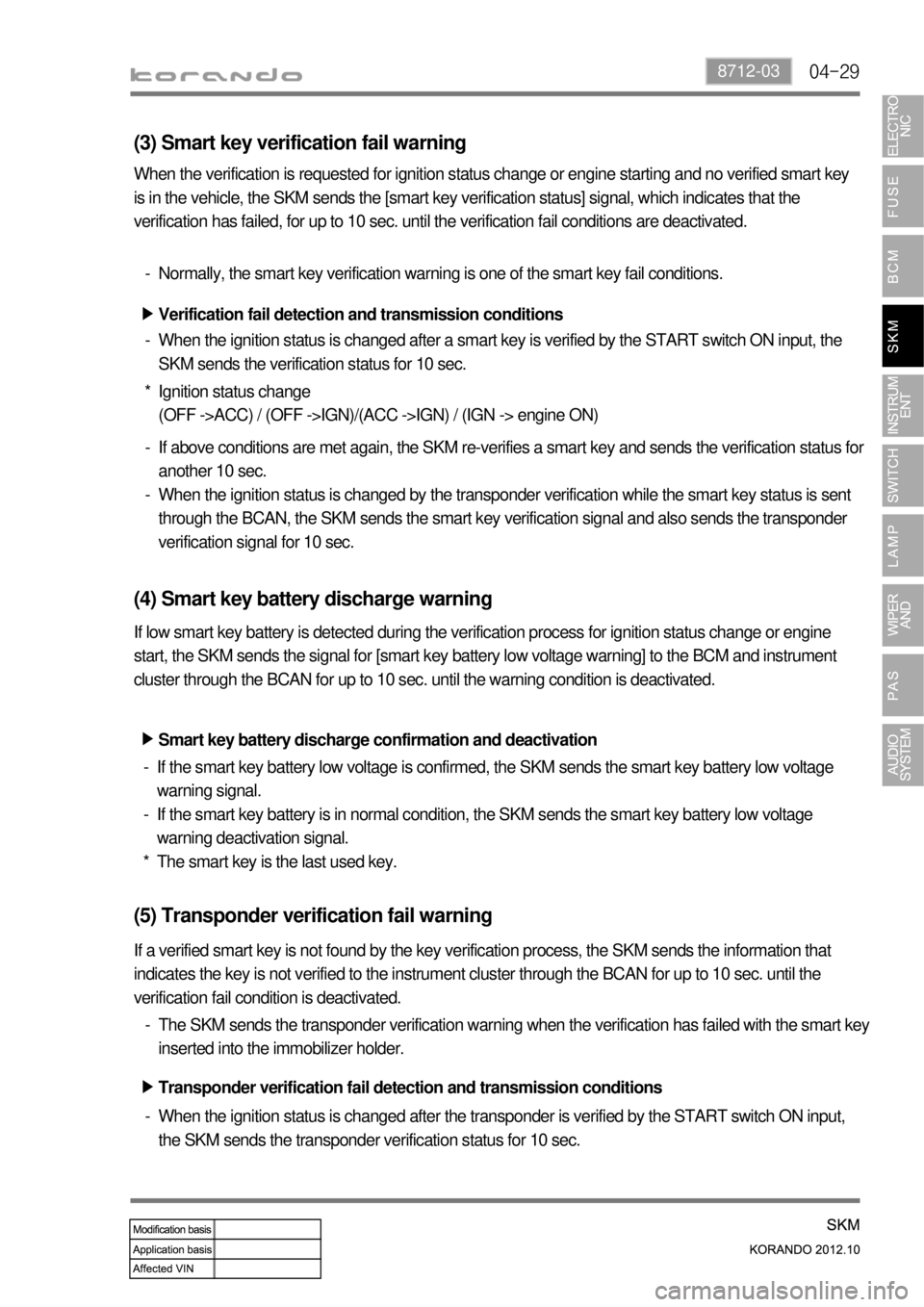
When the verification is requested for ignition status change or engine starting and no verified smart key
is in the vehicle, the SKM sends the [smart key verification status] signal, which indicates that the
verification has failed, for up to 10 sec. until the verification fail conditions are deactivated.
Verification fail detection and transmission conditions ▶
When the ignition status is changed after a smart key is verified by the START switch ON input, the
SKM sends the verification status for 10 sec. -Normally, the smart key verification warning is one of the smart key fail conditions. -
Ignition status change
(OFF ->ACC) / (OFF ->IGN)/(ACC ->IGN) / (IGN -> engine ON) *
If above conditions are met again, the SKM re-verifies a smart key and sends the verification status for
another 10 sec.
When the ignition status is changed by the transponder verification while the smart key status is sent
through the BCAN, the SKM sends the smart key verification signal and also sends the transponder
verification signal for 10 sec. -
-
If low smart key battery is detected during the verification process for ignition status change or engine
start, the SKM sends the signal for [smart key battery low voltage warning] to the BCM and instrument
cluster through the BCAN for up to 10 sec. until the warning condition is deactivated.
Smart key battery discharge confirmation and deactivation ▶
If the smart key battery low voltage is confirmed, the SKM sends the smart key battery low voltage
warning signal.
If the smart key battery is in normal condition, the SKM sends the smart key battery low voltage
warning deactivation signal.
The smart key is the last used key. -
-
*
(5) Transponder verification fail warning
If a verified smart key is not found by the key verification process, the SKM sends the information that
indicates the key is not verified to the instrument cluster through the BCAN for up to 10 sec. until the
verification fail condition is deactivated.
The SKM sends the transponder verification warning when the verification has failed with the smart key
inserted into the immobilizer holder. -
Transponder verification fail detection and transmission conditions ▶
When the ignition status is changed after the transponder is verified by the START switch ON input,
the SKM sends the transponder verification status for 10 sec. -
Page 664 of 1082

04-30
Ignition status change
(OFF ->ACC) / (OFF ->IGN)/(ACC ->IGN) / (IGN -> engine ON) *
If above conditions are met again, the SKM re-verifies the transponder and sends the verification
status for another 10 sec.
When the ignition status is changed by a smart key verification while the transponder verification is
processed, the SKM sends the signal for [transponder verification fail], and sends the smart key
verification status for 10 sec. -
-
(6) Transmission position warning
When the gear selector lever is in a position other than P or N with IGN ON and engine started, the
SKM sends the [gear position warning] signal to the instrument cluster through the BCAN for up to 10
sec. until the operating conditions are deactivated.
Transmission position warning deactivation ▶
When re-attempting to start with IGN1 ON and transmission in P or N -
(7) SKM error alert
The SKM sends the SKM error alert signal to the instrument cluster through the BCAN for up to 10 sec.
when an in ignition status related error or passive entry system error occurs.
SKM error transmission conditions ▶
When any of the following errors is detected and a DTC is set, the SKM sends the error alert signal for
10 sec.
B+ (power) low voltage
B+ (logic) low voltage
ACC ON fail
ACC OFF fail
IGN1 ON fail
IGN1 OFF fail
IGN2 ON fail
IGN2 OFF fail
Short circuit in START switch 1.
2.
3.
4.
5.
6.
7.
8.
9.
The SKM sends the corresponding signal only once for 10 sec. when any of the above errors is detected
with IGN OFF/ON. It sends the signal again when a new error occurs.
Page 665 of 1082
04-318712-03
(8) Brake not working alert
The SKM sends the brake not working alert signal for 10 sec. every time the ignition status is changed
after the 1st cycle (OFF-ACC-IGN-ACC-OFF) while the brake is not operated.
when the brake pedal is depressed, the system is reset and alert deactivation signal is sent.
when the 10 min. timer is terminated -
-
(9) Clutch not working alert
The SKM sends the clutch not working alert signal for 10 sec. every time the ignition status is changed
after the 1st cycle (OFF-ACC-IGN-ACC-OFF)
while the clutch is not operated.
when the clutch pedal is depressed, the system is reset and alert deactivation signal is sent.
when the 10 min. timer is terminated -
-
(10) Smart key slot detection alert
The SKM sends the smart key slot detection alert signal for 10 sec. when a smart key inserted into
the slot is detected with IGN OFF and the driver's door open. -
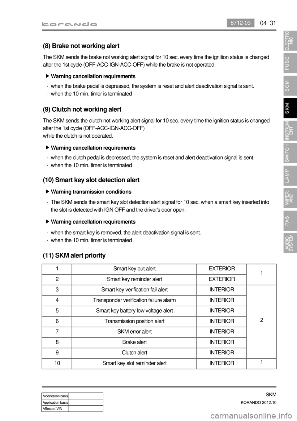
(11) SKM alert priority
1 Smart key out alert EXTERIOR
1
2 Smart key reminder alert EXTERIOR
3 Smart key verification fail alert INTERIOR
2 4 Transponder verification failure alarm INTERIOR
5 Smart key battery low voltage alert INTERIOR
6 Transmission position alert INTERIOR
7 SKM error alert INTERIOR
8 Brake alert INTERIOR
9 Clutch alert INTERIOR
10 Smart key slot reminder alert INTERIOR1
Warning cancellation requirements ▶
Warning cancellation requirements ▶
Warning transmission conditions ▶
Warning cancellation requirements ▶
when the smart key is removed, the alert deactivation signal is sent.
when the 10 min. timer is terminated -
-
Page 746 of 1082
06-358510-00
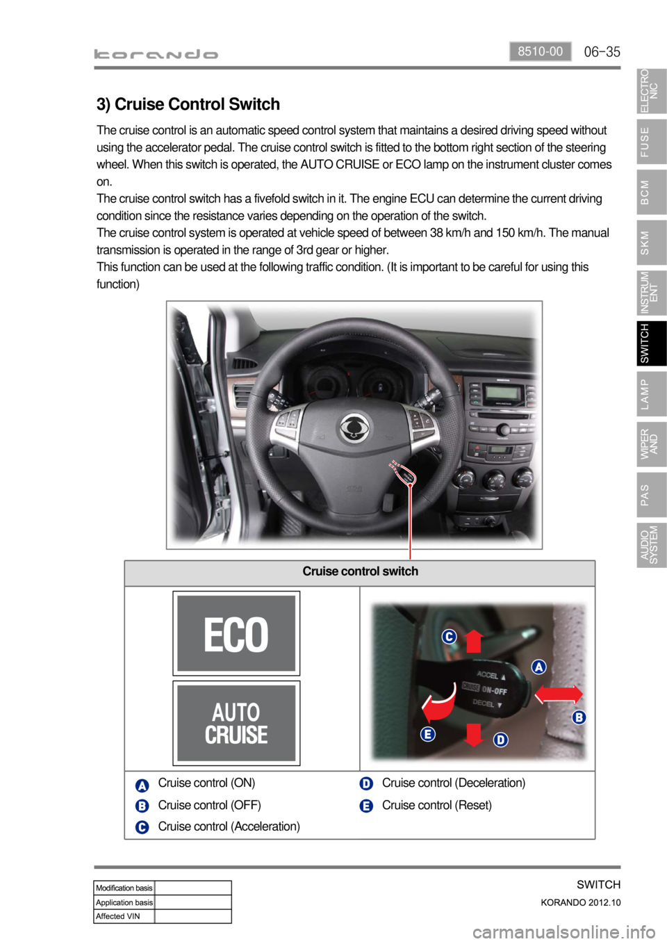
3) Cruise Control Switch
Cruise control switch
The cruise control is an automatic speed control system that maintains a desired driving speed without
using the accelerator pedal. The cruise control switch is fitted to the bottom right section of the steering
wheel. When this switch is operated, the AUTO CRUISE or ECO lamp on the instrument cluster comes
on.
The cruise control switch has a fivefold switch in it. The engine ECU can determine the current driving
condition since the resistance varies depending on the operation of the switch.
The cruise control system is operated at vehicle speed of between 38 km/h and 150 km/h. The manual
transmission is operated in the range of 3rd gear or higher.
This function can be used at the following traffic condition. (It is important to be careful for using this
function)
Cruise control (ON)
Cruise control (OFF)
Cruise control (Acceleration)Cruise control (Deceleration)
Cruise control (Reset)
Page 819 of 1082
01-90000-00
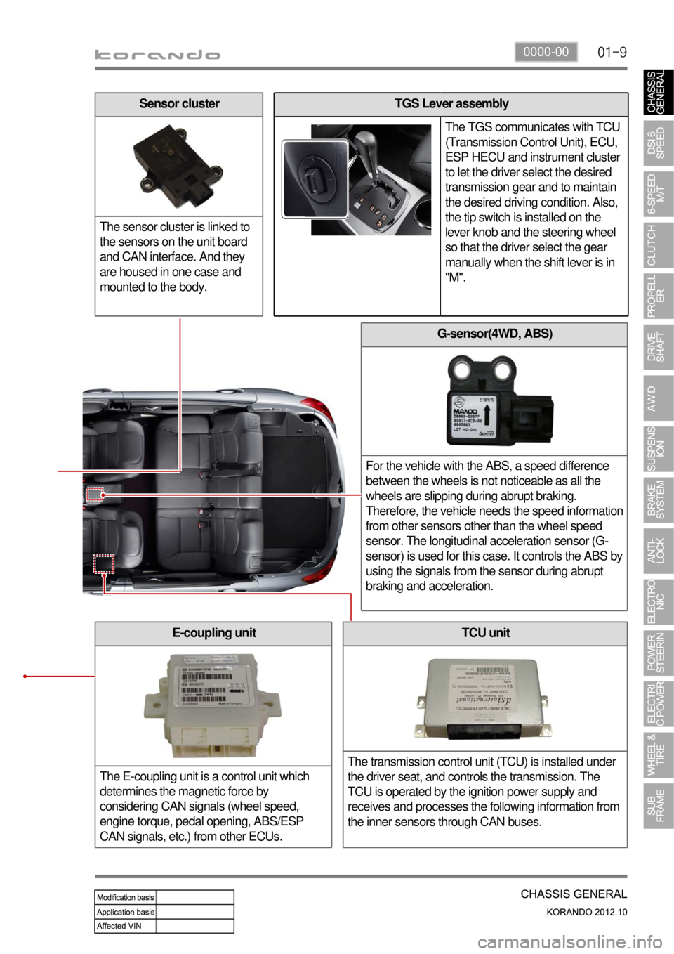
G-sensor(4WD, ABS)
For the vehicle with the ABS, a speed difference
between the wheels is not noticeable as all the
wheels are slipping during abrupt braking.
Therefore, the vehicle needs the speed information
from other sensors other than the wheel speed
sensor. The longitudinal acceleration sensor (G-
sensor) is used for this case. It controls the ABS by
using the signals from the sensor during abrupt
braking and acceleration.
TCU unit
The transmission control unit (TCU) is installed under
the driver seat, and controls the transmission. The
TCU is operated by the ignition power supply and
receives and processes the following information from
the inner sensors through CAN buses.E-coupling unit
The E-coupling unit is a control unit which
determines the magnetic force by
considering CAN signals (wheel speed,
engine torque, pedal opening, ABS/ESP
CAN signals, etc.) from other ECUs.
TGS Lever assembly
The TGS communicates with TCU
(Transmission Control Unit), ECU,
ESP HECU and instrument cluster
to let the driver select the desired
transmission gear and to maintain
the desired driving condition. Also,
the tip switch is installed on the
lever knob and the steering wheel
so that the driver select the gear
manually when the shift lever is in
"M".Sensor cluster
The sensor cluster is linked to
the sensors on the unit board
and CAN interface. And they
are housed in one case and
mounted to the body.
Page 820 of 1082
01-10
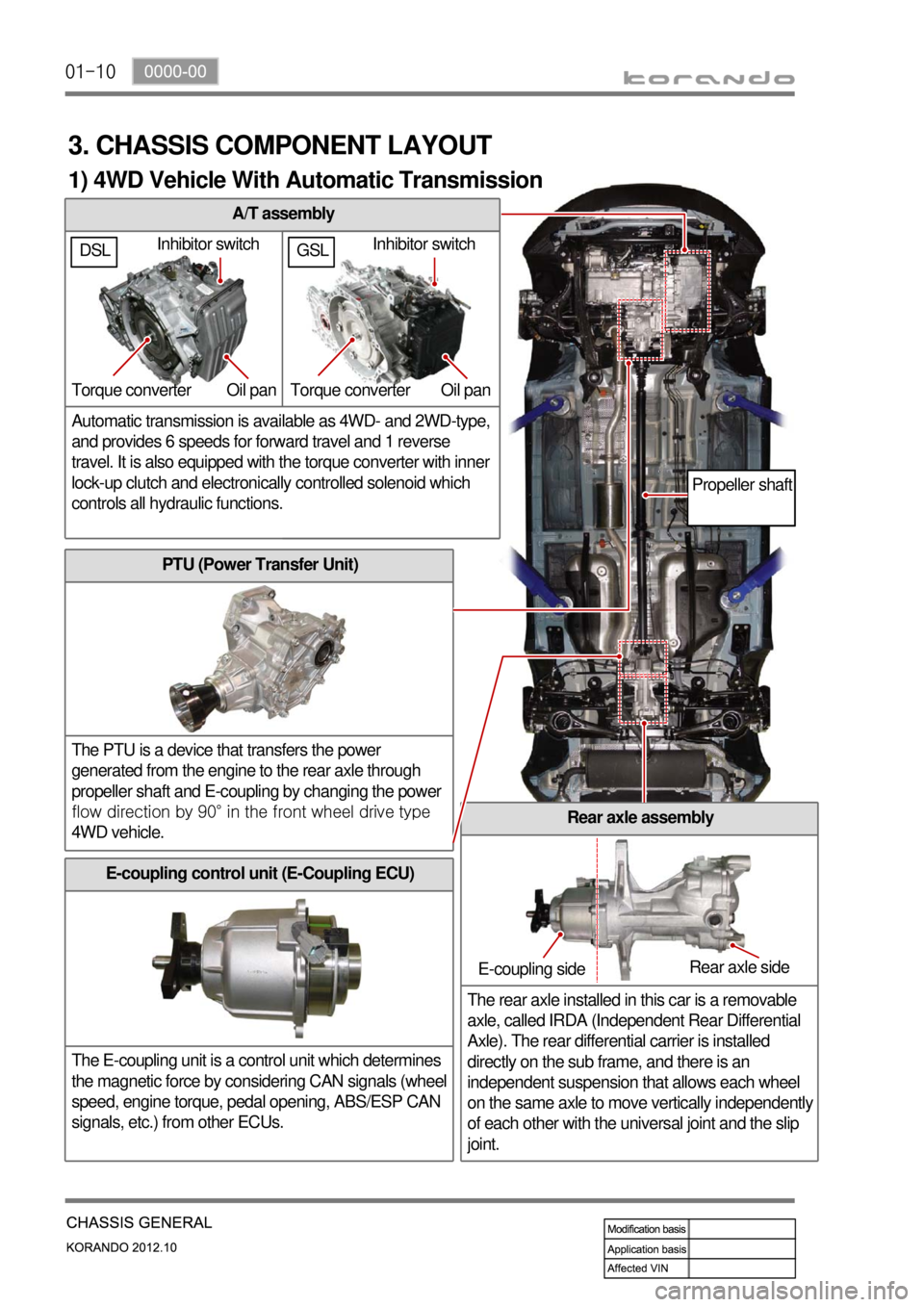
A/T assembly
Automatic transmission is available as 4WD- and 2WD-type,
and provides 6 speeds for forward travel and 1 reverse
travel. It is also equipped with the torque converter with inner
lock-up clutch and electronically controlled solenoid which
controls all hydraulic functions.
3. CHASSIS COMPONENT LAYOUT
PTU (Power Transfer Unit)
The PTU is a device that transfers the power
generated from the engine to the rear axle through
propeller shaft and E-coupling by changing the power
<008d00930096009e0047008b00900099008c008a009b0090009600950047008900a000470060005700b60047009000950047009b008f008c0047008d009900960095009b0047009e008f008c008c00930047008b00990090009d008c0047009b00a0009700
8c0047>
4WD vehicle.
Rear axle assembly
The rear axle installed in this car is a removable
axle, called IRDA (Independent Rear Differential
Axle). The rear differential carrier is installed
directly on the sub frame, and there is an
independent suspension that allows each wheel
on the same axle to move vertically independentl
y
of each other with the universal joint and the slip
joint.
E-coupling control unit (E-Coupling ECU)
The E-coupling unit is a control unit which determines
the magnetic force by considering CAN signals (wheel
speed, engine torque, pedal opening, ABS/ESP CAN
signals, etc.) from other ECUs.
Inhibitor switch
Torque converter Oil pan
E-coupling sideRear axle side
Propeller shaft
1) 4WD Vehicle With Automatic Transmission
GSLDSLInhibitor switch
Torque converter Oil pan
Page 821 of 1082
01-110000-00
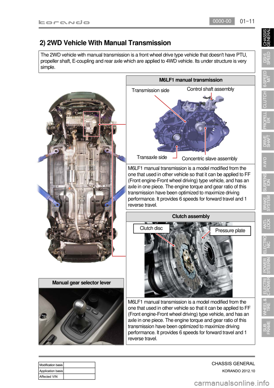
M6LF1 manual transmission
M6LF1 manual transmission is a model modified from the
one that used in other vehicle so that it can be applied to FF
(Front engine-Front wheel driving) type vehicle, and has an
axle in one piece. The engine torque and gear ratio of this
transmission have been optimized to maximize driving
performance. It provides 6 speeds for forward travel and 1
reverse travel.
Clutch assembly
M6LF1 manual transmission is a model modified from the
one that used in other vehicle so that it can be applied to FF
(Front engine-Front wheel driving) type vehicle, and has an
axle in one piece. The engine torque and gear ratio of this
transmission have been optimized to maximize driving
performance. It provides 6 speeds for forward travel and 1
reverse travel.
The 2WD vehicle with manual transmission is a front wheel drive type vehicle that doesn't have PTU,
propeller shaft, E-coupling and rear axle which are applied to 4WD vehicle. Its under structure is very
simple.
Manual gear selector lever
Transmission sideControl shaft assembly
Transaxle side
Concentric slave assembly
Pressure plate
2) 2WD Vehicle With Manual Transmission
Clutch disc
Page 822 of 1082

01-12
Front sub frame with HPS type steering gear box assembly
The front sub frame consists of 4 body bush mountings and 2 transmission
bush mountings which reduce the vibration from the powertrain and road,
and also control the torque. And the frame is equipped with hydraulic
pressure pipe of the HPS type steering gear box.
4. SUB FRAME AND STEERING GEAR BOX LAYOUT
Front sub frame with EPS type steering gear box assembly
This kind of front sub frame system has the same mounting structure with
the frame with HPS. But the EPS type steering gear box has no hydraulic
pressure pipe since it is driven by the electric motor.
Rear side
Front sideHPS type steering
gear box assembly
Front sub frame
assembly
Rear side
Front side
EPS type steering
gear box assembly
Front sub frame
assembly
Page 833 of 1082
01-230000-00
3) General Instructions
Before lifting up the vehicle with a lift, correctly support the lifting points.
When using a jack, park the vehicle on a level ground and place the wheel chocks under the tires.
Position the jack under the frame and lift up the vehicle and then support with chassis stand before
service work.
Make sure to disconnect the negative (-) cable from the battery to prevent any damage to electric
systems.
If you have to work on vehicle, cover the seats and floor with protection covers to avoid any
damage and contamination.
Brake fluid and anti-freeze can damage the painted surface of body. So carefully handle them
during service work.
To improve the efficiency of service work, use only recommended and specified tools.
Use only Ssangyong genuine spare parts.
Never reuse the cotter pin, gasket, O-ring, oil seal, lock washer and self-locking nut. Replace them
with new ones. If reused, normal functions cannot be maintained.
Store the disassembled parts as a set based on disassembly order and unit.
Pay particular attention not to miss or mix the fasteners.
If necessary, especially for inspection, clean the removed parts completely.
Apply the oil or grease on the running and sliding surfeces before installation. Use the specified
sealant and gasket to prevent leakage if necessary.
Tighten the fasteners to the specified tightening torque.
As a final stage of service work, check if the serviced system is working properly and the problem
has been eliminated clearly. (1)
(2)
(3)
(4)
(5)
(6)
(7)
(8)
(9)
(10)
(11)
(12)
(13)
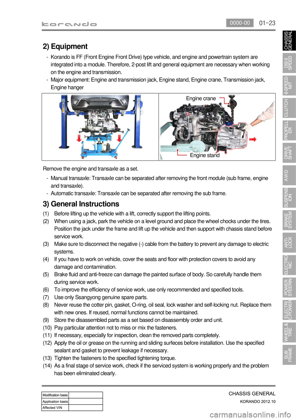
(14) Remove the engine and transaxle as a set.
Manual transaxle: Transaxle can be separated after removing the front module (sub frame, engine
and transaxle).
Automatic transaxle: Transaxle can be separated after removing the sub frame. -
-
2) Equipment
Korando is FF (Front Engine Front Drive) type vehicle, and engine and powertrain system are
integrated into a module. Therefore, 2-post lift and general equipment are necessary when working
on the engine and transmission.
Major equipment: Engine and transmission jack, Engine stand, Engine crane, Transmission jack,
Engine hanger -
-
Engine stand
Engine crane