oil temperature SSANGYONG KORANDO 2012 Owner's Manual
[x] Cancel search | Manufacturer: SSANGYONG, Model Year: 2012, Model line: KORANDO, Model: SSANGYONG KORANDO 2012Pages: 1082, PDF Size: 96.1 MB
Page 468 of 1082
15-31490-00
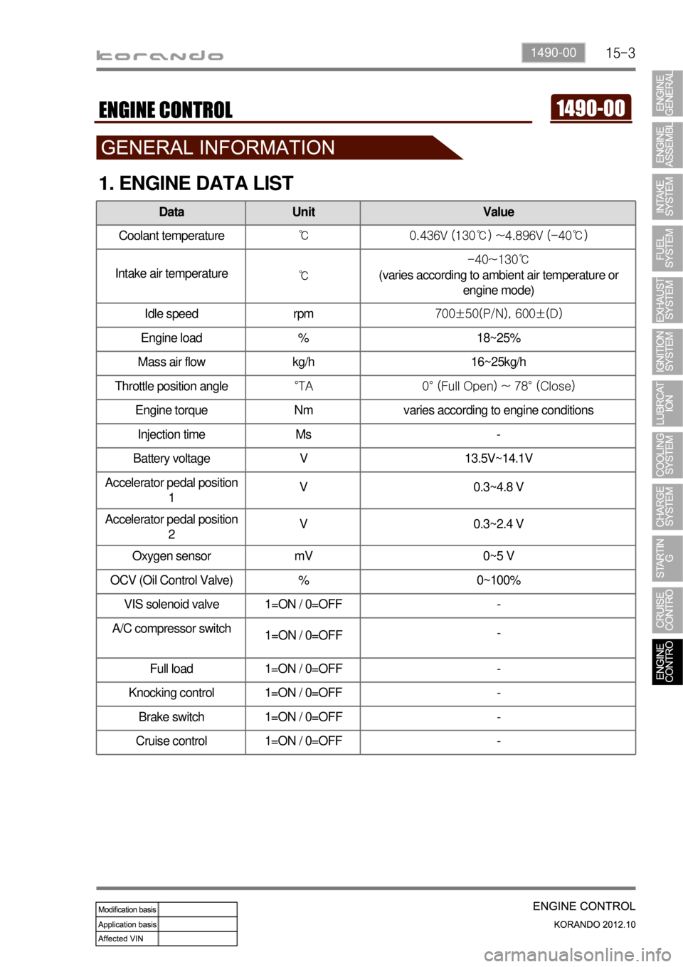
1. ENGINE DATA LIST
Data Unit Value
Coolant temperature℃ 0.436V (130℃) ~4.896V (-40℃)
Intake air temperature
℃-40~130℃
(varies according to ambient air temperature or
engine mode)
Idle speed rpm700±50(P/N), 600±(D)
Engine load % 18~25%
Mass air flow kg/h 16~25kg/h
Throttle position angle°TA 0° (Full Open) ~ 78° (Close)
Engine torque Nm varies according to engine conditions
Injection time Ms -
Battery voltage V 13.5V~14.1V
Accelerator pedal position
1V 0.3~4.8 V
Accelerator pedal position
2V 0.3~2.4 V
Oxygen sensor mV 0~5 V
OCV (Oil Control Valve) % 0~100%
VIS solenoid valve 1=ON / 0=OFF -
A/C compressor switch
1=ON / 0=OFF-
Full load 1=ON / 0=OFF -
Knocking control 1=ON / 0=OFF -
Brake switch 1=ON / 0=OFF -
Cruise control 1=ON / 0=OFF -
Page 472 of 1082
15-70000-00
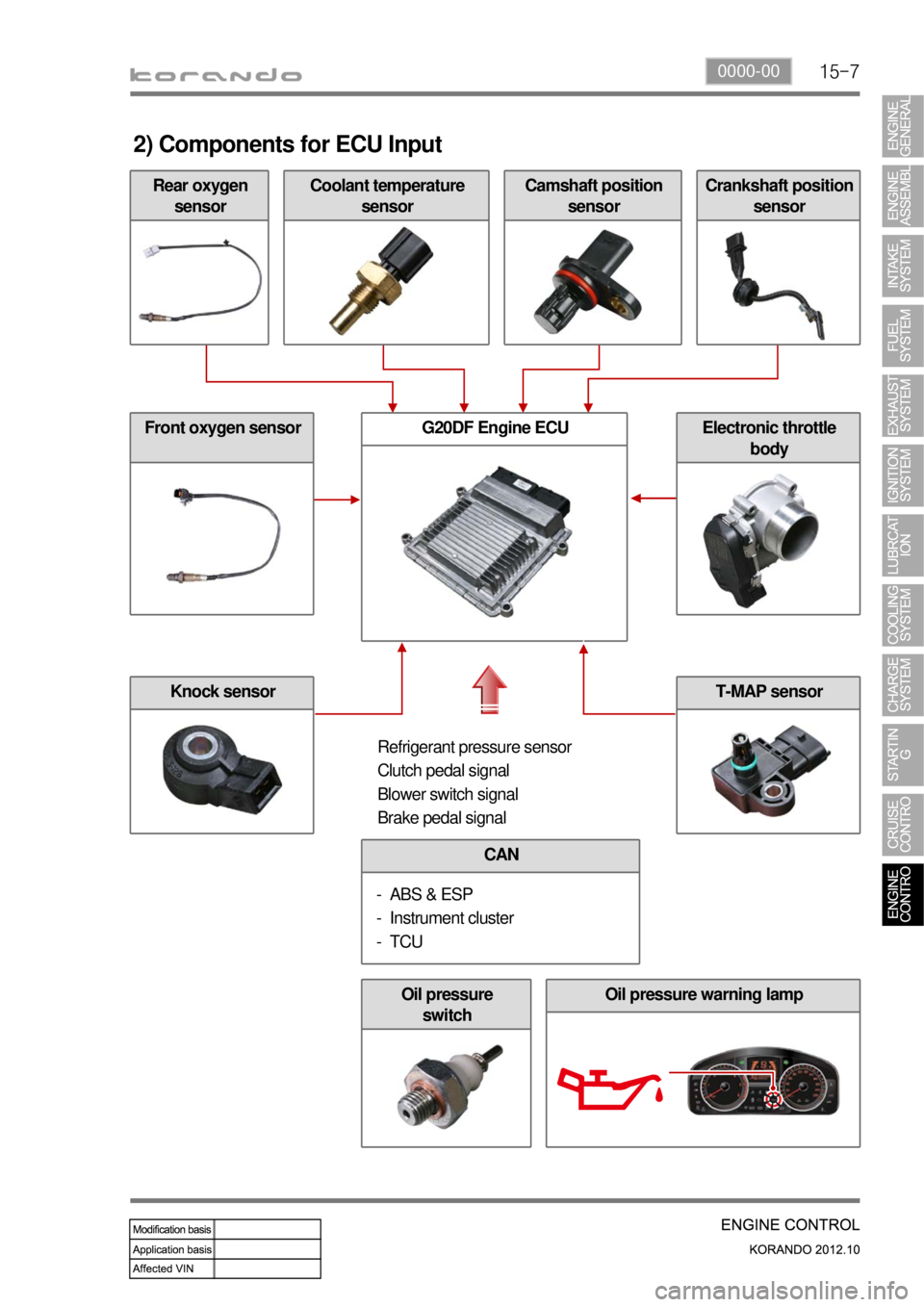
Rear oxygen
sensor
2) Components for ECU Input
Coolant temperature
sensorCamshaft position
sensorCrankshaft position
sensor
Front oxygen sensor
Knock sensor
G20DF Engine ECUElectronic throttle
body
Refrigerant pressure sensor
Clutch pedal signal
Blower switch signal
Brake pedal signal
CAN
ABS & ESP
Instrument cluster
TCU -
-
-
Oil pressure
switchOil pressure warning lamp
T-MAP sensor
Page 474 of 1082
15-91490-00
3. ECU CONTROL
1) Functions
ECU receives and analyzes signals from various sensors and then modifies those signals into
permissible voltage levels and analyzes to control respective actuators.
ECU microprocessor calculates injection period and injection timing proper for engine piston speed and
crankshaft angle based on input data and stored specific map to control the engine power and emission
gas.
Output signal of the ECU microprocessor activates the injector solenoid valve to control the fuel injection
period and injection timing; so controls various actuators in response to engine changes.
Auxiliary function of ECU has adopted to reduce emission gas, improve fuel economy and enhance
safety, comforts and conveniences. For example, there are autocruise and immobilizer and adopted
CAN communication to exchange data among electrical systems (automatic T/M and brake system) in
the vehicle fluently. And the diagnostic tool can be used to diagnose vehicle status and defectives.
<00760097008c00990088009b00900095008e0047009b008c00940097008c00990088009b009c0099008c0047009900880095008e008c00470096008d0047006c006a007c00470090009a0047009500960099009400880093009300a000470054005b005700
47009b009600470052005f005c00b6006a004700880095008b> protected from factors like oil,
water and electromagnetism and there should be no mechanical shocks.
2) Control Functions
Controls by operating stages:
To make optimum combustion under every operating stage, ECU should calculate proper injection
volume in each stage by considering various factors.
Starting injection volume control:
During initial starting, injecting fuel volume will be calculated by function of temperature and engine
cranking speed. Starting injection continues from when the ignition switch is turned to ignition
position to till the engine reaches to allowable minimum speed.
Driving mode control:
If the vehicle runs normally, fuel injection volume will be calculated by accelerator pedal travel and
engine rpm and the drive map will be used to match the drivers inputs with optimum engine power. -
-
-
Page 478 of 1082

15-130000-00
Coolant temperature
sensor
4) Ignition System Control
(1) Overview
G20DF engine is equipped with the single ignition system. Each spark plug is operated independently
by the ECU and one ignition coil and spark plug are provided for each cylinder.
(2) Components
Input Components ▶
Crankshaft position
sensorAccelerator pedal position
sensor
Knock sensorCamshaft position
sensorElectronic
throttle body
Output Components ▶
Page 483 of 1082
15-18
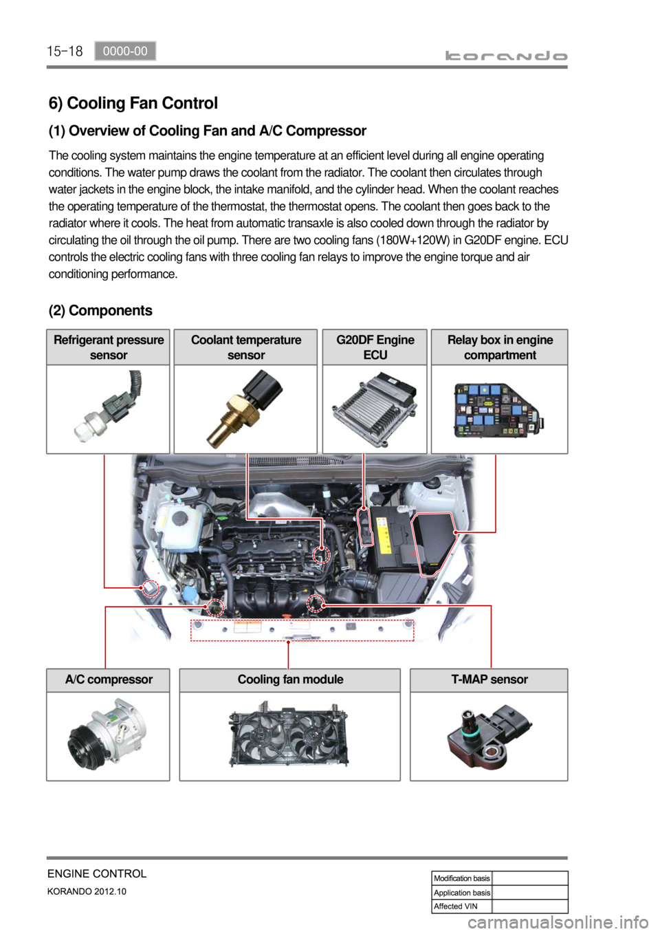
6) Cooling Fan Control
(1) Overview of Cooling Fan and A/C Compressor
The cooling system maintains the engine temperature at an efficient level during all engine operating
conditions. The water pump draws the coolant from the radiator. The coolant then circulates through
water jackets in the engine block, the intake manifold, and the cylinder head. When the coolant reaches
the operating temperature of the thermostat, the thermostat opens. The coolant then goes back to the
radiator where it cools. The heat from automatic transaxle is also cooled down through the radiator by
circulating the oil through the oil pump. There are two cooling fans (180W+120W) in G20DF engine. ECU
controls the electric cooling fans with three cooling fan relays to improve the engine torque and air
conditioning performance.
(2) Components
Refrigerant pressure
sensorCoolant temperature
sensorG20DF Engine
ECURelay box in engine
compartment
A/C compressorCooling fan moduleT-MAP sensor
Page 839 of 1082
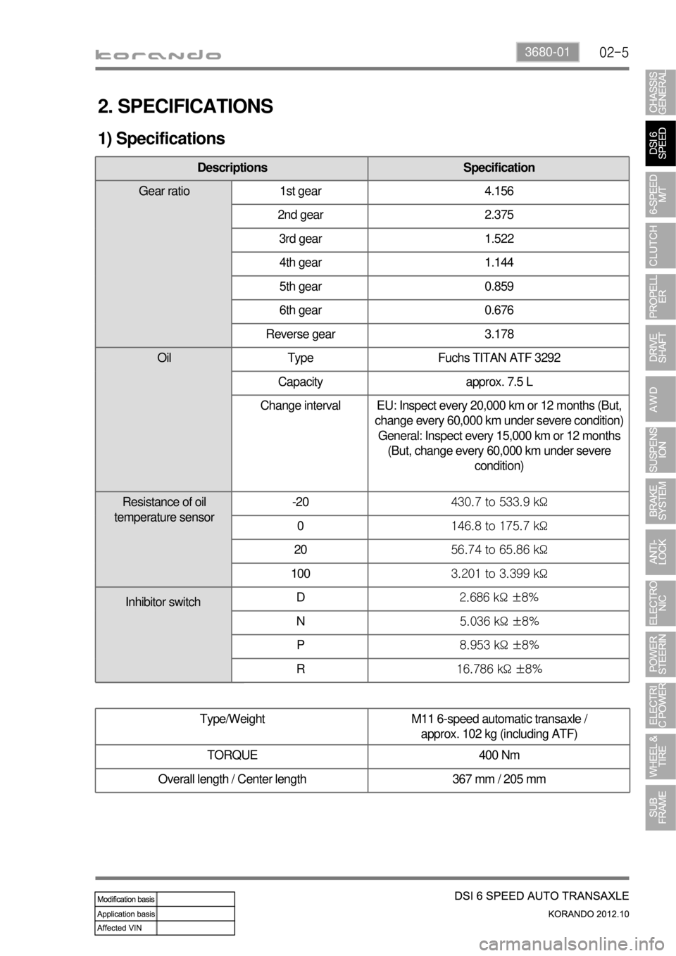
02-53680-01
2. SPECIFICATIONS
1) Specifications
Type/Weight M11 6-speed automatic transaxle /
approx. 102 kg (including ATF)
TORQUE 400 Nm
Overall length / Center length 367 mm / 205 mm
Descriptions Specification
Gear ratio 1st gear 4.156
2nd gear 2.375
3rd gear 1.522
4th gear 1.144
5th gear 0.859
6th gear 0.676
Reverse gear 3.178
Oil Type Fuchs TITAN ATF 3292
Capacity approx. 7.5 L
Change interval EU: Inspect every 20,000 km or 12 months (But,
change every 60,000 km under severe condition)
General: Inspect every 15,000 km or 12 months
(But, change every 60,000 km under severe
condition)
Resistance of oil
temperature sensor-20430.7 to 533.9 kΩ
0146.8 to 175.7 kΩ
2056.74 to 65.86 kΩ
1003.201 to 3.399 kΩ
D2.686 kΩ ±8%
N5.036 kΩ ±8%
P8.953 kΩ ±8%
R16.786 kΩ ±8%
Inhibitor switch
Page 842 of 1082
02-8
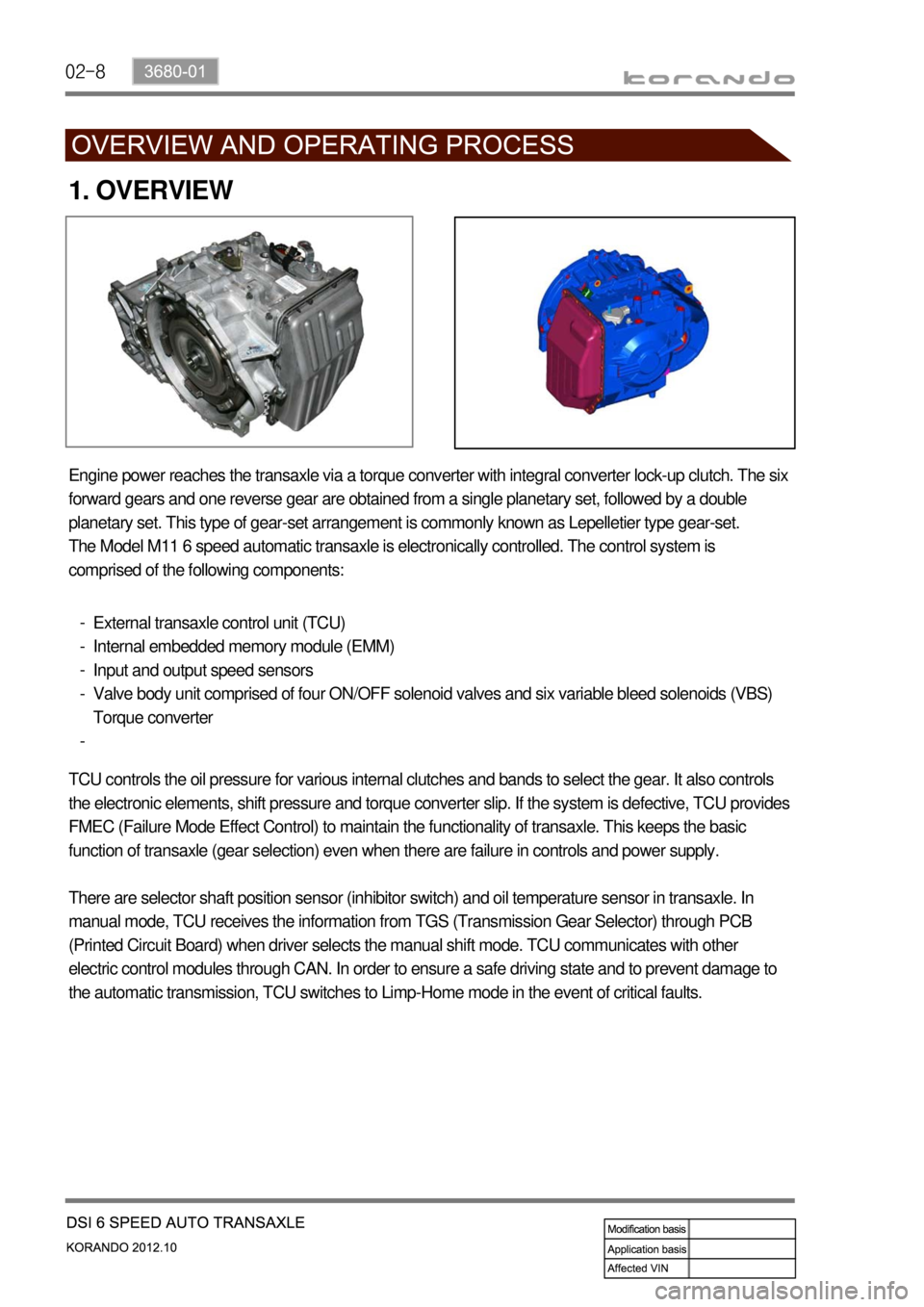
1. OVERVIEW
Engine power reaches the transaxle via a torque converter with integral converter lock-up clutch. The six
forward gears and one reverse gear are obtained from a single planetary set, followed by a double
planetary set. This type of gear-set arrangement is commonly known as Lepelletier type gear-set.
The Model M11 6 speed automatic transaxle is electronically controlled. The control system is
comprised of the following components:
External transaxle control unit (TCU)
Internal embedded memory module (EMM)
Input and output speed sensors
Valve body unit comprised of four ON/OFF solenoid valves and six variable bleed solenoids (VBS)
Torque converter -
-
-
-
-
TCU controls the oil pressure for various internal clutches and bands to select the gear. It also controls
the electronic elements, shift pressure and torque converter slip. If the system is defective, TCU provides
FMEC (Failure Mode Effect Control) to maintain the functionality of transaxle. This keeps the basic
function of transaxle (gear selection) even when there are failure in controls and power supply.
There are selector shaft position sensor (inhibitor switch) and oil temperature sensor in transaxle. In
manual mode, TCU receives the information from TGS (Transmission Gear Selector) through PCB
(Printed Circuit Board) when driver selects the manual shift mode. TCU communicates with other
electric control modules through CAN. In order to ensure a safe driving state and to prevent damage to
the automatic transmission, TCU switches to Limp-Home mode in the event of critical faults.
Page 848 of 1082
02-14
5. TRANSAXLE ELECTRONIC CONTROL SYSTEM
1) General Information
The transmission control unit (TCU) and its input/output network control the following transmission
operations:
Shift timing
Line pressure
Clutch pressure (shift feel)
Torque converter clutch -
-
-
-
also uses these signals when determining transaxle operating strategy. Using all of these input signals,
the TCU can determine when the time and conditions are right for a shift, or when to apply or release the
torque converter clutch. It will also determine the pressure needed to optimise shift feel. To accomplish
this, the TCU operates six variable bleed control solenoids and four on/off solenoids to control transaxle
operation.
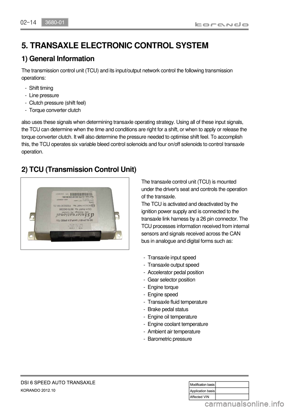
2) TCU (Transmission Control Unit)
The transaxle control unit (TCU) is mounted
under the driver's seat and controls the operation
of the transaxle.
The TCU is activated and deactivated by the
ignition power supply and is connected to the
transaxle link harness by a 26 pin connector. The
TCU processes information received from internal
sensors and signals received across the CAN
bus in analogue and digital forms such as:
Transaxle input speed
Transaxle output speed
Accelerator pedal position
Gear selector position
Engine torque
Engine speed
Transaxle fluid temperature
Brake pedal status
Engine oil temperature
Engine coolant temperature
Ambient air temperature
Barometric pressure -
-
-
-
-
-
-
-
-
-
-
-
Page 866 of 1082
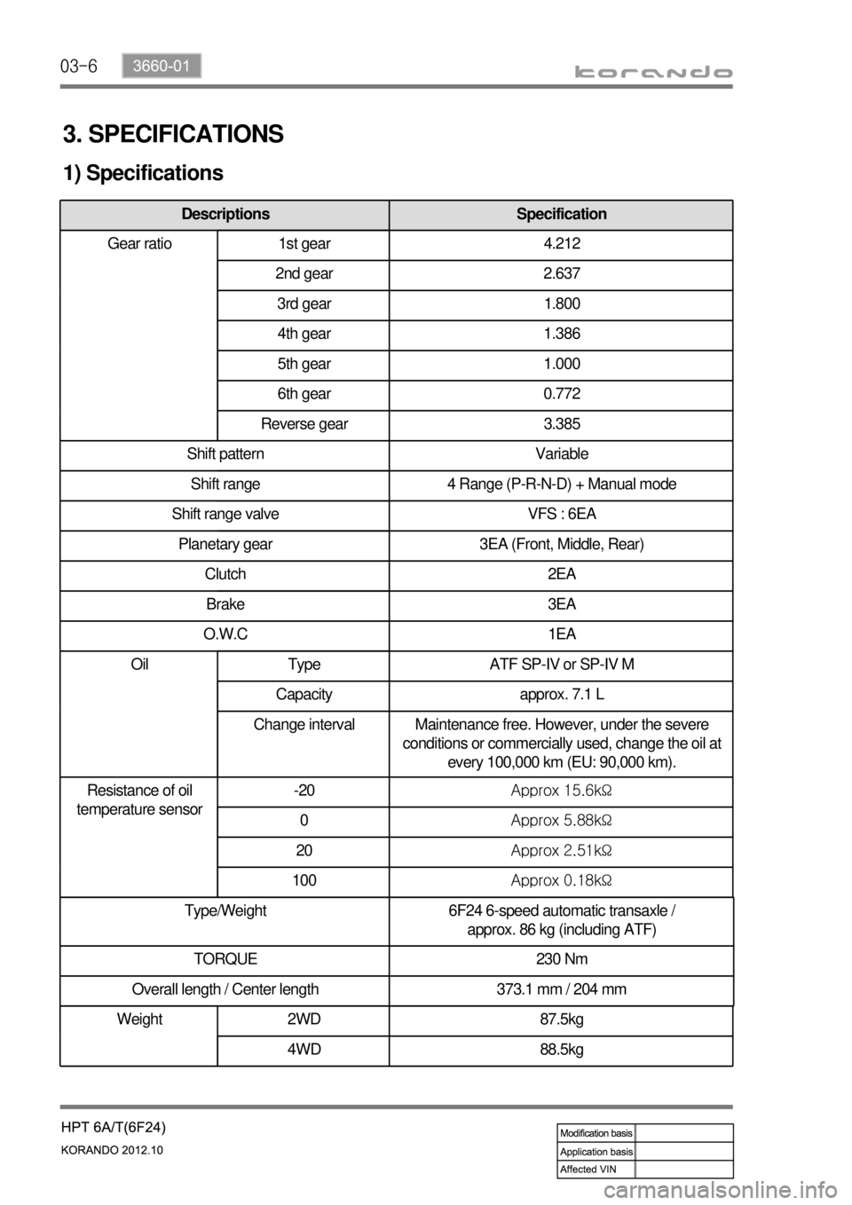
03-6
3. SPECIFICATIONS
1) Specifications
Type/Weight 6F24 6-speed automatic transaxle /
approx. 86 kg (including ATF)
TORQUE 230 Nm
Overall length / Center length 373.1 mm / 204 mm
Descriptions Specification
Gear ratio 1st gear 4.212
2nd gear 2.637
3rd gear 1.800
4th gear 1.386
5th gear 1.000
6th gear 0.772
Reverse gear 3.385
Shift pattern Variable
Shift range 4 Range (P-R-N-D) + Manual mode
Shift range valve VFS : 6EA
Planetary gear 3EA (Front, Middle, Rear)
Clutch 2EA
Brake 3EA
O.W.C 1EA
Oil Type ATF SP-IV or SP-IV M
Capacity approx. 7.1 L
Change interval Maintenance free. However, under the severe
conditions or commercially used, change the oil at
every 100,000 km (EU: 90,000 km).
Resistance of oil
temperature sensor-20Approx 15.6kΩ
0Approx 5.88kΩ
20Approx 2.51kΩ
100Approx 0.18kΩ
Weight 2WD 87.5kg
4WD 88.5kg
Page 868 of 1082

03-8
Automatic transaxle Bolt (engine) 17 mm X 4
14 mm X 1 85.0 ~ 100.0Nm
Bolt (start motor) 14 mm X 2 48.0 ~ 58.8Nm
Bolt (oil pan) 14 mm X 4 56.0 ~ 62.0Nm
Bolt (torque converter) 17 mm X 6 45.0 ~ 52.0Nm
Eye bolt 22 mm X 1 3.0 ~ 5.0Nm
Drain plug 24 mm X 1 34.0 ~ 44.0Nm
Nut (range select lever) 14 mm X 1 17.6 ~ 24.5Nm
Bolt (inhibitor switch) 10 mm X 2 9.8 ~ 11.7Nm
Bolt (oil pan) 10 mm X 19 12.0 ~ 14.0Nm
Bolt (solenoid harness) 10 mm X 6 9.8 ~ 11.7Nm
Bolt (oil temperature sensor) 10 mm X 1 9.8 ~ 11.7Nm
Bolt (input & output sensor) 10 mm X 2 9.8 ~ 11.7Nm
Bolt (detent spring) 12 mm X 1 12.0 ~ 16.0Nm
Bolt (valve body) 10 mm X 8 9.8 ~ 11.7Nm
Bolt (V/B solenoid bracket) H5 mm X 9 9.8 ~ 11.7Nm
Bolt (torque converter housing) 12 mm X 20 28.0 ~ 35.0Nm
Bolt (oil guide A) 10 mm X 3 9.8 ~ 11.7Nm
Bolt (oil guide B) 10 mm X 1 5.0 ~ 7.0Nm
Bolt (oil filter) H5 mm X 2 9.8 ~ 11.7Nm
5. TIGHTENING TORQUE
DescriptionsSize x
NumbersTightening torque
(Nm)
TGS lever Nut 12 mm X 4 17.6 ~ 21.6Nm
Nut (manual control lever) 13 mm X 1 14.0 ~ 20.0Nm
Nut (floor) 12 mm X 1 17.6 ~ 21.6Nm
Nut (dash panel) 12 mm X 2 17.6 ~ 21.6Nm
A/T bracket Bolt (left bracket) 17 mm X 3 88.2 ~ 107.8Nm
Bolt (right bracket) 17 mm X 4 88.2 ~ 107.8Nm
Bolt (upper bracket) 17 mm X 4 88.2 ~ 107.8Nm
TGS lever
TGS cable