rear wheel SSANGYONG KORANDO 2012 Owner's Manual
[x] Cancel search | Manufacturer: SSANGYONG, Model Year: 2012, Model line: KORANDO, Model: SSANGYONG KORANDO 2012Pages: 1082, PDF Size: 96.1 MB
Page 903 of 1082
04-70000-00
Operating Elements ▶
The clutch "release" system consists of the clutch pedal and clutch release cylinder.
This system directly releases the clutch by using hydraulic pressure while the conventional clutch system
releases the clutch by using release lever and release fork. This system provides higher efficiency than
conventional clutch system, and its durability is superior.
Clutch master cylinder (mounted on clutch pedal)
Concentric slave cylinder pipe (mounted inside of transmission) -
-Driving elements ▶
The driving elements consist of two flat surfaces machined to a smooth finish.
One of these is the rear face of the engine flywheel and the other is the clutch pressure plate. The clutch
pressure plate is fitted into a clutch steel cover, which is bolted to the flywheel.
Driven elements ▶
The driven element is the clutch disc with a splined hub which is free to slide lengthwise along the splines
of the input shaft.
The driving and driven elements are held in contact by spring pressure. This pressure is exerted by a
diaphragm spring in the clutch cover pressure plate assembly.
2) Overview
Page 912 of 1082
06-6
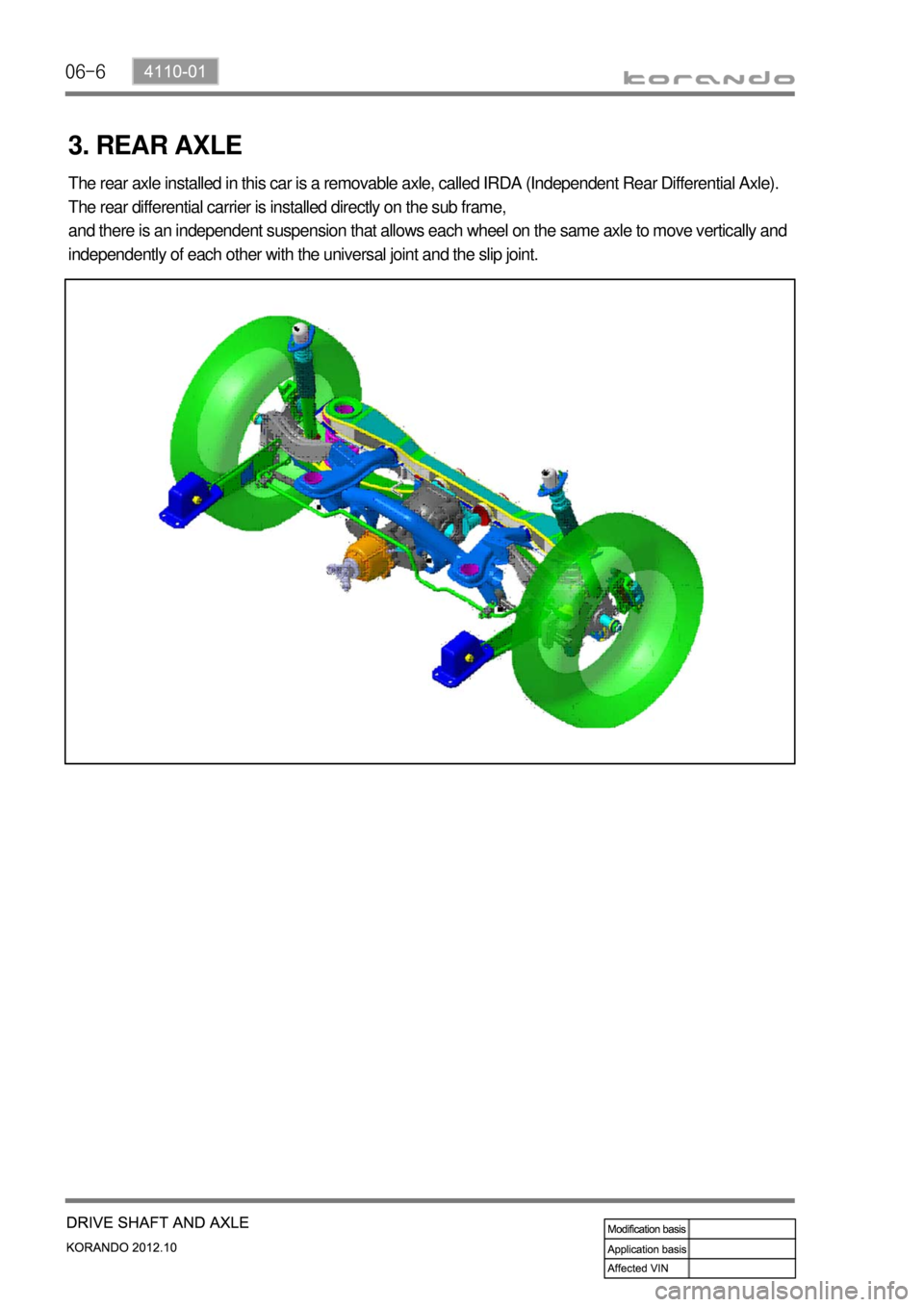
3. REAR AXLE
The rear axle installed in this car is a removable axle, called IRDA (Independent Rear Differential Axle).
The rear differential carrier is installed directly on the sub frame,
and there is an independent suspension that allows each wheel on the same axle to move vertically and
independently of each other with the universal joint and the slip joint.
Page 914 of 1082

07-4
1. OVERVIEW
The AWD system in this vehicle is the electronic 4WD system and controls the traction to rear wheels
according to the driving conditions.
1) Driving Mode
(1) AUTO mode (Normal driving mode)
Normally the vehicle is in 2WD mode.
Automatically change to this mode when the vehicle needs higher traction.
(2) LOCK mode (when pressing 4WD LOCK switch)
This mode provides the highest traction. Use
this mode when driving on unpaved, rugged,
steep, sandy, wet or slippery roads.
In 4WD LOCK mode, if the rear wheel speed
exceeds 40 km/h, 4WD LOCK mode is
canceled and 4WD AUTO mode is activated
(Indicator OFF). If the speed is decreased
below 35 km/h, 4WD LOCK mode is resumed
(Indicator ON again). -
-
Mode table ▶
4WD LOCK switch Vehicle speed Driving mode
Not pressed (4WD AUTO) No conditions 4WD AUTO
Pressed (4WD LOCK) over 40 km/h 4WD AUTO
Pressed (4WD LOCK) below 35 km/h 4WD LOCK
Page 915 of 1082

07-50000-00
2. SYSTEM LAYOUT
1) Components
(1) PTU (Power Transfer Unit)
<007b008f008c004700970096009e008c00990047009b009900880095009a008d008c00990047009c00950090009b0047009000950047009b008f008c0047008d009900960095009b0047009e008f008c008c00930047008b00990090009d008c0047009400
96008b008c00930047008a008f00880095008e008c009a0047>the angle of engine torque to 90°
and transfer it to E-coupling to distribute the torque to rear wheels.
(2) E-Coupling (Electronic Coupling)
E-Coupling transfer the engine torque from PTU to rear axle and controls to distribute it between front
wheels and rear wheels.
(3) E-Coupling Control Unit (ECU)
E-Coupling controls the current (clutch engagement force) of EMCD in E-Coupling according to CAN
signals (wheel speed, engine torque, pedal position, ABS/ESP signals).
* EMCD: Electro-Magnetic Control Device PTU assemblyE-coupling control unit
(located on the floor under driver seat)E-coupling
Page 917 of 1082

08-4
1) Wheel Alignment
System Description Specification
Front Ground clearance (A)76.8 ± 5 mm
Trim height : wheel
center ↔ Wheel
house433 mm
Camber (maintenance
free)-0.15 ± 0.5˚
Caster (maintenance
free)4.8 ± 0.5˚
Total toe-in0.0 ± 0.1˚
(adjust by tie rod)
King pin angle12.85˚
Rear Ground clearance (A)63.3 ± 5 mm
Trim height : wheel
center ↔ Wheel
house437 mm
Camber (maintenance
free)-0.5 ± 0.5˚
[ adjust by cam bolt on
upper arm ]
Total toe-in0.0 ± 0.1˚
[ adjust by cam bolt on
track rod ]
Page 924 of 1082

09-4
3) Parts Arrangement
Part nameVehicle with
CBSVehicle with ABS/EBDVehicle with
ESP
HECU
Not appliedAppliedApplied Front wheel speed sensor
Rear wheel speed sensor
ABS warning lamp
EBD indicator
Longitudinal G sensor 2WD: N/A, 4WD: Applied Not applied
Sensor cluster
(Yaw rate sensor,
lateral/longitudinal G sensor)
Not applied Applied
ESP indicator
ESP OFF switch and warning
lamp
Steering wheel angle sensor
Page 925 of 1082
09-54850-00
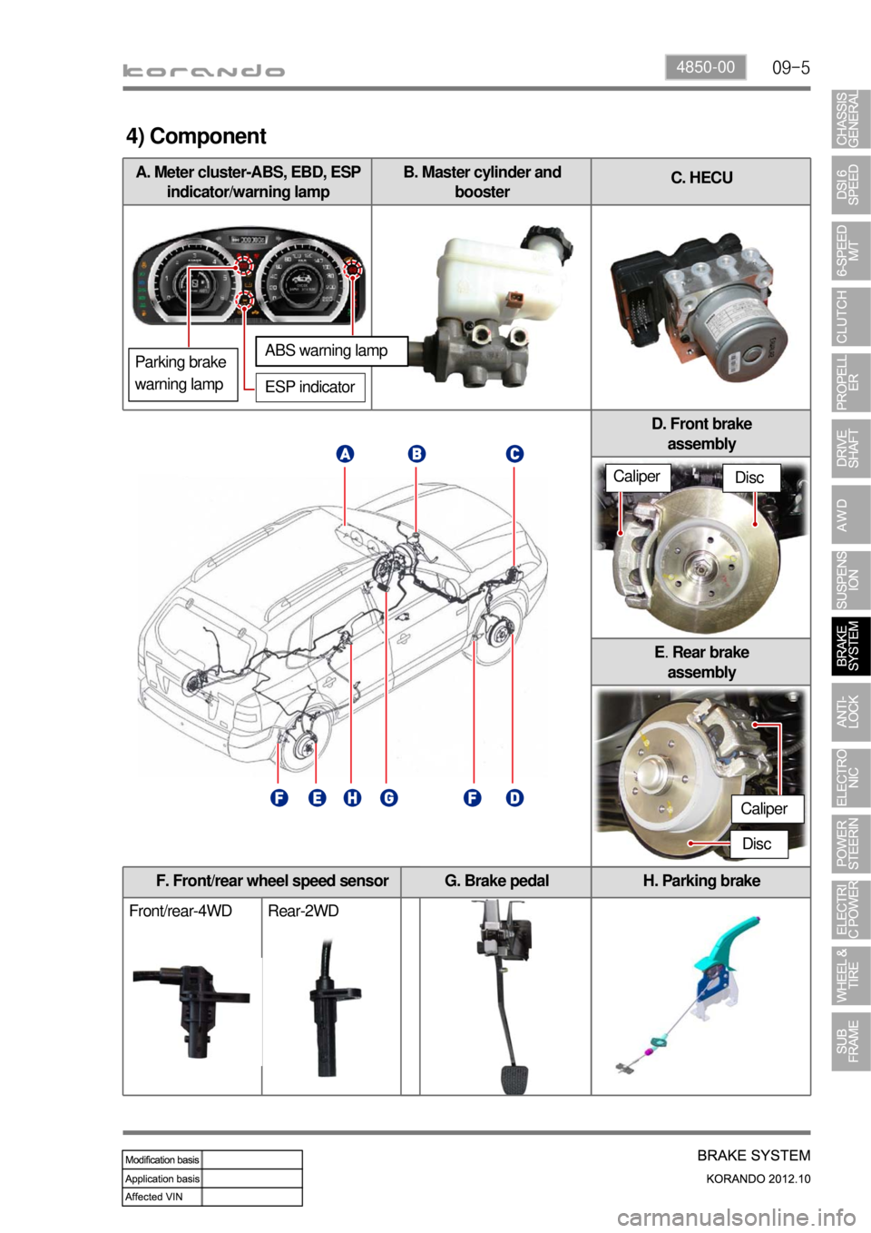
F. Front/rear wheel speed sensor
Front/rear-4WD Rear-2WDH. Parking brake
A. Meter cluster-ABS, EBD, ESP
indicator/warning lampB. Master cylinder and
boosterC. HECU
G. Brake pedal
4) Component
ABS warning lamp
ESP indicator
D. Front brake
assembly
E. Rear brake
assembly
Disc
Disc
Parking brake
warning lamp
Caliper
Caliper
Page 927 of 1082
09-74850-00
1. OVERVIEW
Even though a driver cuts off the power, while driving, the vehicle continues to move due to the law of
inertia. Therefore, a braking device is needed to stop the vehicle. The brake system normally uses the
frictional discs that converts the kinetic energy to the thermal energy by frictional operation. The brake
system consists of the brake disc (front wheel), brake disc or drum (rear wheel), parking brake
(mechanical type), master cylinder, booster, pedal and supply lines (pipes and hoses).
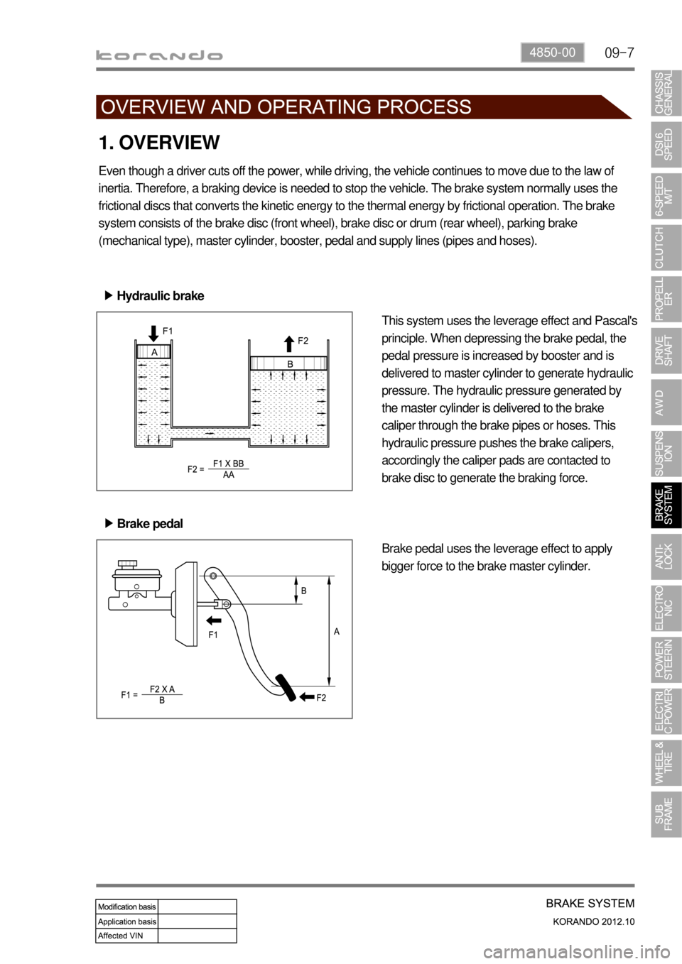
Hydraulic brake ▶
Brake pedal ▶This system uses the leverage effect and Pascal's
principle. When depressing the brake pedal, the
pedal pressure is increased by booster and is
delivered to master cylinder to generate hydraulic
pressure. The hydraulic pressure generated by
the master cylinder is delivered to the brake
caliper through the brake pipes or hoses. This
hydraulic pressure pushes the brake calipers,
accordingly the caliper pads are contacted to
brake disc to generate the braking force.
Brake pedal uses the leverage effect to apply
bigger force to the brake master cylinder.
Page 929 of 1082

09-94850-00
Rear disc brake ▶
Caliper
Brake hose
Brake disc
KnuckleWheel disc
Brake hub
Brake disc
Fastener Tightening torque Remark
Brake pad guide bolt 25.5 ~ 30.4Nm 14 mm x 2EA
Brake caliper mounting bolt 52.9 ~ 63.7Nm 17 mm x 2EA
Brake hose bolt 19.6 ~ 29.4Nm 12mm
Brake hose bracket mounting bolt 9.8 ~ 12.8Nm 12mm
Air breather screw 8.8 ~ 10.8Nm -
1) Tightening torque
Page 937 of 1082
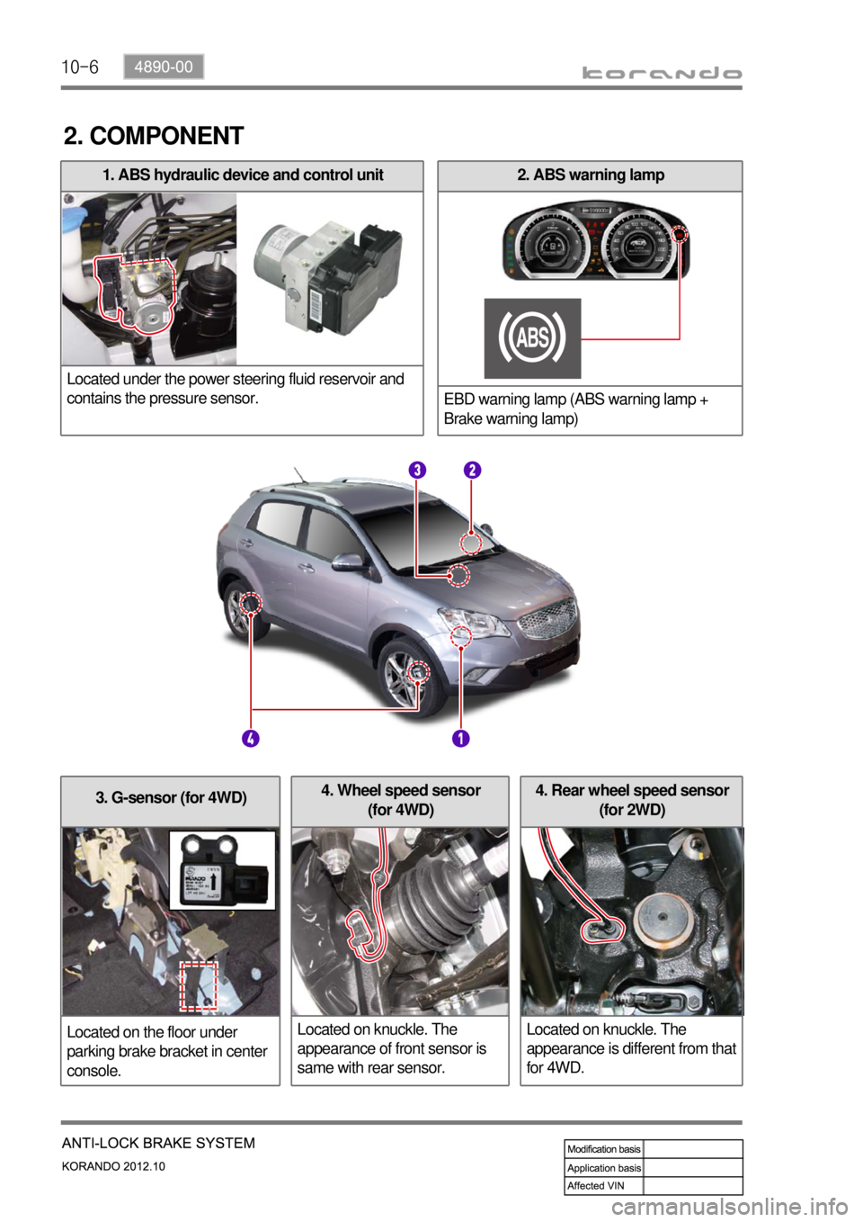
10-6
3. G-sensor (for 4WD)
Located on the floor under
parking brake bracket in center
console.4. Rear wheel speed sensor
(for 2WD)
Located on knuckle. The
appearance is different from that
for 4WD.4. Wheel speed sensor
(for 4WD)
Located on knuckle. The
appearance of front sensor is
same with rear sensor.
2. ABS warning lamp
EBD warning lamp (ABS warning lamp +
Brake warning lamp)1. ABS hydraulic device and control unit
Located under the power steering fluid reservoir and
contains the pressure sensor.
2. COMPONENT