reset SSANGYONG KORANDO 2012 Owner's Manual
[x] Cancel search | Manufacturer: SSANGYONG, Model Year: 2012, Model line: KORANDO, Model: SSANGYONG KORANDO 2012Pages: 1082, PDF Size: 96.1 MB
Page 876 of 1082

03-16
4. LIMP HOME MODE
When the transaxle is defective ▶
In the event of a system fault, the TCU also provides for failure mode effect control (FMEC) to maintain
maximum functional operation of the transaxle. (There are 3 FMEC modes, mechanical limp-home
mode, electrical limp-home mode, limp-home mode C.)
In the event of a total loss of control or electrical power, the basic transaxle functions (Park, Reverse,
Neutral and Drive) are retained. The 4th and reverse gear ratios with the torque converter clutch in the
unlocked state are the retained gear states the hydraulic system supports without any electrical
assistance. (Mechanical limp-home)
If the speed sensor circuit is failed, the gear is fixed to 4th gear, but manual shifting
<004f00590095008b02e9005a0099008b02e9005b009b008f005000470090009a00470088009d008800900093008800890093008c0055004f006c0093008c008a009b00990090008a00880093004700930090009400970047008f00960094008c0047009400
96008b008c0050>
If the inhibitor switch signals are invalid, shifting to1st and 2nd gear is forbidden. (Limp-home C)
The TCU communicates with other vehicle electronic control modules by the controller area network
(CAN). If a major fault is developed, the transaxle may not accomplish the intelligent shift control. The
TCU controls the transaxle with preset values.
The TCU also provides for transaxle diagnostics, which meet the requirements of OBD II regulation,
monitoring all components which may effect vehicle emissions. 1.
2.
3.
4.
5.
6.
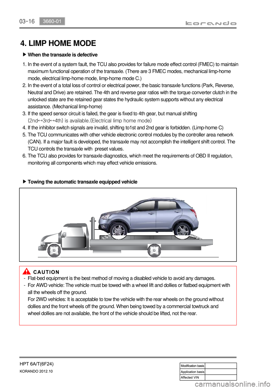
Towing the automatic transaxle equipped vehicle ▶
Flat-bed equipment is the best method of moving a disabled vehicle to avoid any damages.
For AWD vehicle: The vehicle must be towed with a wheel lift and dollies or flatbed equipment with
all the wheels off the ground.
For 2WD vehicles: It is acceptable to tow the vehicle with the rear wheels on the ground without
dollies and the front wheels off the ground. When being towed by a commercial towtruck and
wheel dollies are not available, the front of the vehicle should be lifted, not the rear. -
-
Page 1032 of 1082

02-16
3) CAN Communication Interface (FIS and SIS)
The CAN communication interface uses the PWM for the supply current and the current loop and
communicates with the SDM to transmit the information. The serial communication and power for the
satellite are supplied through the communication line.
Stage FIS SIS
Initial stage Tracking/Check (Self test) Same as FIS
Normal operation Checks the FIS condition and sends the result as
"OK" or "NOK", and also sends the "severity" of the
crash. Same as FIS
Voltage The FIS hardware reset was performed under 5 V,
communication voltage low Same as FIS
Fault The fault is found in the current ignition cycle but the
fault is deactivated in the next ignition cycle. Multiple faults can be found
and deactivated in the same
ignition cycle.
The FIS moves to the initial stage if 'leakage to GND' is occurred in normal operating stage to shut down
the power and prevent abnormal operation.
※ FIS: Front Impact Sensor
SIS: Side Air bag Sensor
Page 1040 of 1082

04-37340-00
1. SPECIFICATIONS
2. CAUTIONS WHEN WORKING
Wear clean work clothes and gloves.
Replace and wash the gloves frequently.
Any unauthorized modification or operational test is not allowed since the sunroof motor and control
unit are preset at the factory.
You can use basic tools, e.g. a 25T/10T star screwdriver, flat-bladed and cross-tip screwdrivers. Do
not use any similar tool.
Take care not to drop the sunroof assembly when removing it and do not keep it right up. 1.
2.
3.
4.
5.
Operating voltage 9 to 16 V
Operating current (open & close) Max. 6 A
At no load Approx. 3 A
Leakage current Max. 1 mA or less
Roof motor operating speed
(at opening and closing)1.4 ± 0.5 sec./100 mm
Motor overload stop conditionsCurrent for 25 A or higher and torque (load) for 7.5 Nm
or higher
2-step opening amount1st step sliding open: 370 ± 5 mm
2nd step sliding open: 450 ± 5 mm
Vertical/horizontal tolerance for
sunroof glass panel± 2 mm
Page 1047 of 1082

04-10
4. ZERO POINT SETTING
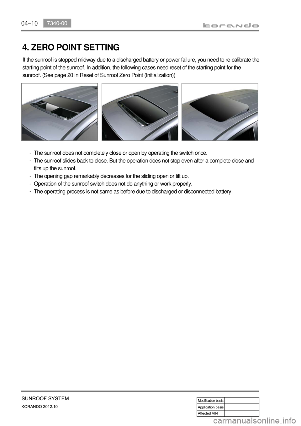
If the sunroof is stopped midway due to a discharged battery or power failure, you need to re-calibrate the
starting point of the sunroof. In addition, the following cases need reset of the starting point for the
sunroof. (See page 20 in Reset of Sunroof Zero Point (Initialization))
The sunroof does not completely close or open by operating the switch once.
The sunroof slides back to close. But the operation does not stop even after a complete close and
tilts up the sunroof.
The opening gap remarkably decreases for the sliding open or tilt up.
Operation of the sunroof switch does not do anything or work properly.
The operating process is not same as before due to discharged or disconnected battery. -
-
-
-
-