service SSANGYONG KORANDO 2012 Owner's Manual
[x] Cancel search | Manufacturer: SSANGYONG, Model Year: 2012, Model line: KORANDO, Model: SSANGYONG KORANDO 2012Pages: 1082, PDF Size: 96.1 MB
Page 497 of 1082

01-90000-00
4. SCHEDULED MAINTENANCE SERVICES
Page 502 of 1082
02-30000-00
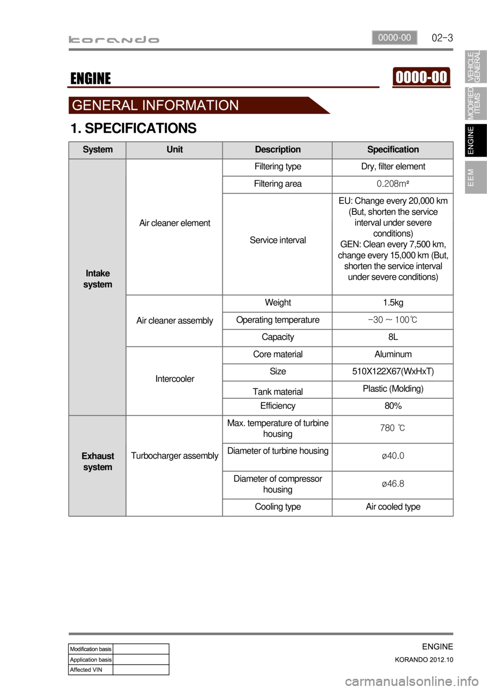
1. SPECIFICATIONS
System Unit Description Specification
Intake
systemAir cleaner elementFiltering type Dry, filter element
Filtering area0.208m²
Service intervalEU: Change every 20,000 km
(But, shorten the service
interval under severe
conditions)
GEN: Clean every 7,500 km,
change every 15,000 km (But,
shorten the service interval
under severe conditions)
Air cleaner assemblyWeight 1.5kg
Operating temperature-30 ~ 100℃
Capacity 8L
IntercoolerCore material Aluminum
Size 510X122X67(WxHxT)
Tank materialPlastic (Molding)
Efficiency 80%
Exhaust
systemTurbocharger assemblyMax. temperature of turbine
housing780 ℃
Diameter of turbine housing
ø40.0
Diameter of compressor
housingø46.8
Cooling type Air cooled type
Page 807 of 1082
10-58910-05
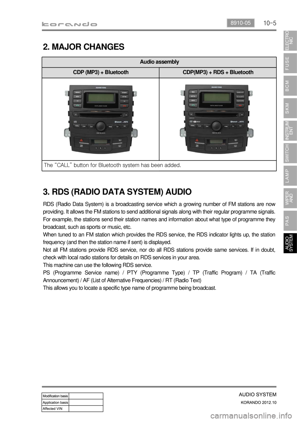
Audio assembly
CDP (MP3) + Bluetooth CDP(MP3) + RDS + Bluetooth
<007b008f008c004702c8006a00680073007302c900470089009c009b009b009600950047008d00960099004700690093009c008c009b00960096009b008f0047009a00a0009a009b008c00940047008f0088009a00470089008c008c009500470088008b00
8b008c008b0055>
2. MAJOR CHANGES
RDS (Radio Data System) is a broadcasting service which a growing number of FM stations are now
providing. It allows the FM stations to send additional signals along with their regular programme signals.
For example, the stations send their station names and information about what type of programme they
broadcast, such as sports or music, etc.
When tuned to an FM station which provides the RDS service, the RDS indicator lights up, the station
frequency (and then the station name if sent) is displayed.
Not all FM stations provide RDS service, nor do all RDS stations provide same services. If in doubt,
check with local radio stations for details on RDS services in your area.
This machine can use the following RDS service.
PS (Programme Service name) / PTY (Programme Type) / TP (Traffic Program) / TA (Traffic
Announcement) / AF (List of Alternative Frequencies) / RT (Radio Text)
This allows you to locate a specific type name of programme being broadcast.
3. RDS (RADIO DATA SYSTEM) AUDIO
Page 832 of 1082

01-22
1. GUIDELINES FOR SERVICE WORKS
1) For Safety
To perform the service works easily ans safely, the service technicians must keep the proper working
procedures and rules.
This manual provides the useful instructions to the service technicians so that they can perform the
servive works with standard working process, skills, tips in time.
Please read this manual and follow the instructions carefully.
Signal words such as “WARNING”, “CAUTION” and “NOTE” have special meanings.
indicates information to assist maintenance and instructions.
However, above references and cautions cannot be inclusive measures, so should have habits of
paying attentions and cautions based on common senses.
indicates a potentially hazardous situation which, if not avoided, may result in minor or moderate
injury or property damage.
indicates a potentially hazardous situation which, if not avoided, could result in death or serious
injury.
Page 833 of 1082
01-230000-00
3) General Instructions
Before lifting up the vehicle with a lift, correctly support the lifting points.
When using a jack, park the vehicle on a level ground and place the wheel chocks under the tires.
Position the jack under the frame and lift up the vehicle and then support with chassis stand before
service work.
Make sure to disconnect the negative (-) cable from the battery to prevent any damage to electric
systems.
If you have to work on vehicle, cover the seats and floor with protection covers to avoid any
damage and contamination.
Brake fluid and anti-freeze can damage the painted surface of body. So carefully handle them
during service work.
To improve the efficiency of service work, use only recommended and specified tools.
Use only Ssangyong genuine spare parts.
Never reuse the cotter pin, gasket, O-ring, oil seal, lock washer and self-locking nut. Replace them
with new ones. If reused, normal functions cannot be maintained.
Store the disassembled parts as a set based on disassembly order and unit.
Pay particular attention not to miss or mix the fasteners.
If necessary, especially for inspection, clean the removed parts completely.
Apply the oil or grease on the running and sliding surfeces before installation. Use the specified
sealant and gasket to prevent leakage if necessary.
Tighten the fasteners to the specified tightening torque.
As a final stage of service work, check if the serviced system is working properly and the problem
has been eliminated clearly. (1)
(2)
(3)
(4)
(5)
(6)
(7)
(8)
(9)
(10)
(11)
(12)
(13)
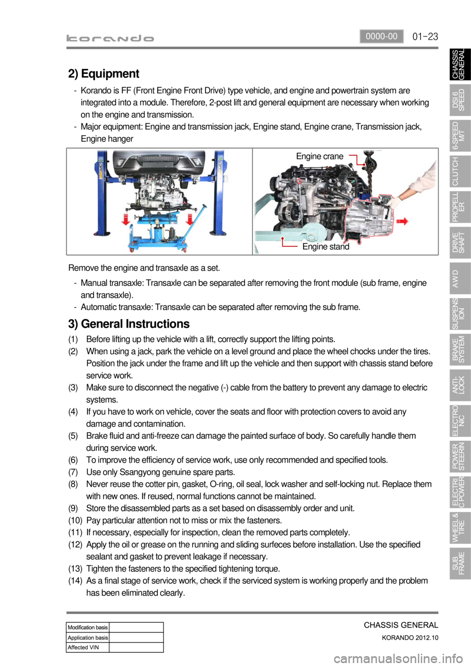
(14) Remove the engine and transaxle as a set.
Manual transaxle: Transaxle can be separated after removing the front module (sub frame, engine
and transaxle).
Automatic transaxle: Transaxle can be separated after removing the sub frame. -
-
2) Equipment
Korando is FF (Front Engine Front Drive) type vehicle, and engine and powertrain system are
integrated into a module. Therefore, 2-post lift and general equipment are necessary when working
on the engine and transmission.
Major equipment: Engine and transmission jack, Engine stand, Engine crane, Transmission jack,
Engine hanger -
-
Engine stand
Engine crane
Page 849 of 1082
02-153680-01
This information is used by the TCU to decide which shift pattern to select and for shift energy
management. Electro-hydraulic solenoid valves and variable bleed solenoids control the transaxle gear
changes.
Six variable bleed solenoids and four on/off solenoids are used to direct transaxle fluid flow to control the
fluid pressure within the three clutches and two bands. Separate pressure regulators are used
exclusively for torque converter clutch control and main transaxle line pressure.
The TCU monitors all TCU inputs and outputs to confirm correct system operation. If a fault occurs the
TCU is able to perform default action and inform the driver of the problem through the instrument cluster
warning lights. Detailed information is available via trouble codes which can be read with the service tool.
Page 870 of 1082
03-10
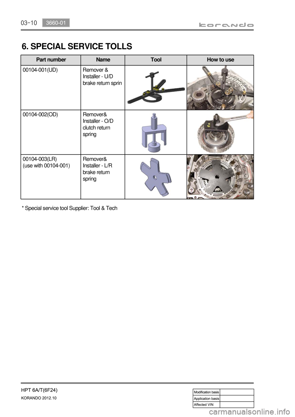
6. SPECIAL SERVICE TOLLS
Part number Name Tool How to use
00104-001(UD) Remover &
Installer - U/D
brake return sprin
00104-002(OD) Remover&
Installer - O/D
clutch return
spring
00104-003(LR)
(use with 00104-001)Remover&
Installer - L/R
brake return
spring
* Special service tool Supplier: Tool & Tech
Page 877 of 1082
03-173660-01
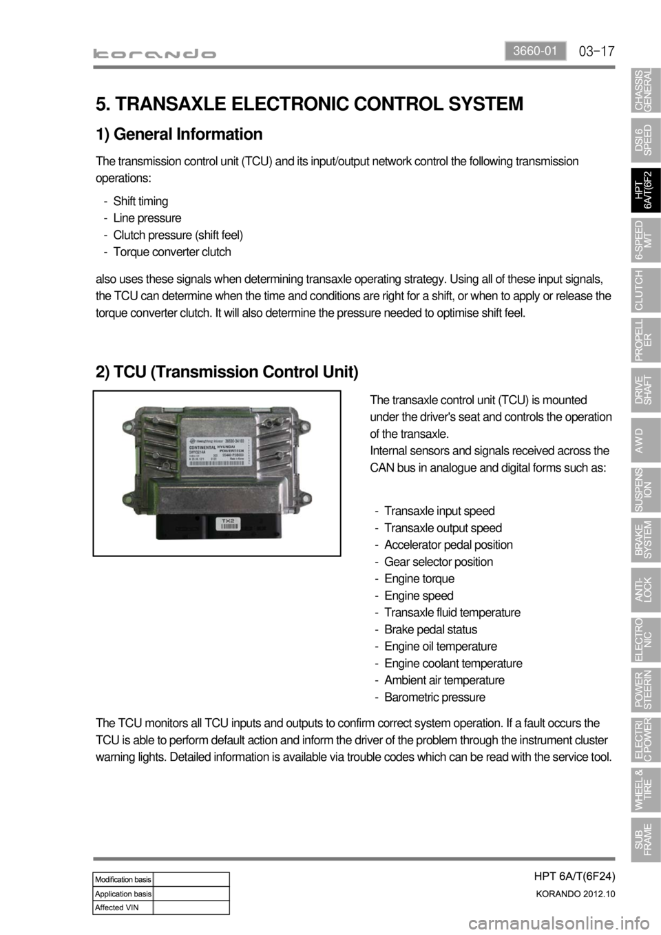
5. TRANSAXLE ELECTRONIC CONTROL SYSTEM
1) General Information
The transmission control unit (TCU) and its input/output network control the following transmission
operations:
Shift timing
Line pressure
Clutch pressure (shift feel)
Torque converter clutch -
-
-
-
also uses these signals when determining transaxle operating strategy. Using all of these input signals,
the TCU can determine when the time and conditions are right for a shift, or when to apply or release the
torque converter clutch. It will also determine the pressure needed to optimise shift feel.
2) TCU (Transmission Control Unit)
The transaxle control unit (TCU) is mounted
under the driver's seat and controls the operation
of the transaxle.
Internal sensors and signals received across the
CAN bus in analogue and digital forms such as:
Transaxle input speed
Transaxle output speed
Accelerator pedal position
Gear selector position
Engine torque
Engine speed
Transaxle fluid temperature
Brake pedal status
Engine oil temperature
Engine coolant temperature
Ambient air temperature
Barometric pressure -
-
-
-
-
-
-
-
-
-
-
-
The TCU monitors all TCU inputs and outputs to confirm correct system operation. If a fault occurs the
TCU is able to perform default action and inform the driver of the problem through the instrument cluster
warning lights. Detailed information is available via trouble codes which can be read with the service tool.
Page 926 of 1082
09-6
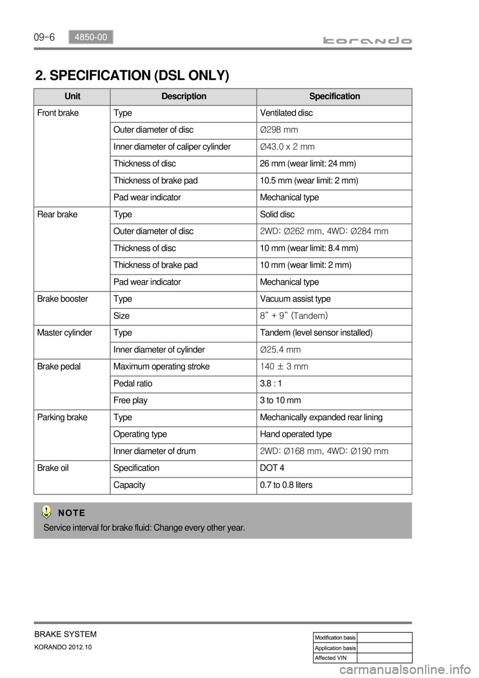
2. SPECIFICATION (DSL ONLY)
Unit Description Specification
Front brake Type Ventilated disc
Outer diameter of discØ298 mm
Inner diameter of caliper cylinderØ43.0 x 2 mm
Thickness of disc 26 mm (wear limit: 24 mm)
Thickness of brake pad 10.5 mm (wear limit: 2 mm)
Pad wear indicator Mechanical type
Rear brake Type Solid disc
Outer diameter of disc2WD: Ø262 mm, 4WD: Ø284 mm
Thickness of disc 10 mm (wear limit: 8.4 mm)
Thickness of brake pad 10 mm (wear limit: 2 mm)
Pad wear indicator Mechanical type
Brake booster Type Vacuum assist type
Size8” + 9” (Tandem)
Master cylinder Type Tandem (level sensor installed)
Inner diameter of cylinderØ25.4 mm
Brake pedal Maximum operating stroke140 ± 3 mm
Pedal ratio 3.8 : 1
Free play 3 to 10 mm
Parking brake Type Mechanically expanded rear lining
Operating type Hand operated type
Inner diameter of drum2WD: Ø168 mm, 4WD: Ø190 mm
Brake oil Specification DOT 4
Capacity 0.7 to 0.8 liters
Service interval for brake fluid: Change every other year.
Page 1022 of 1082

02-6
Seldom oeprate ▶The air bag deploys when: ▶
The air bag can deploy when: ▶a severe oblique collision occurs with a specific severity, angle, speed, and position. -
A collision with oblique impact to the front seat direction or a front collision to the diagonal
direction occurs.
a frontal or rear collision occurs.
The vehicle rolls over or tips over sideward with minor impact.
The air bag warning lamp is on. -
-
-
-the vehicle rolls over or tips over sideward with a severe impact.
The vehicle is stationary or a front collision occurs with low speed.
A rear collision occurs.
The impact of the collision is low enough for the seat belt to protect the occupant properly. -
-
-
-
Seldom oeprate ▶The air bag deploys when: ▶
The air bag can deploy when: ▶
The air bag does not deploy when: ▶
The vehicle is stationary or a front collision occurs with low speed.
A rear collision occurs.
The impact of the collision is low enough for the seat belt to protect the occupant properly. -
-
-
C. General Warnings for Air Bag
Do not check the circuits with a circuit tester. Do not attempt to modify any air bag component
including the steering wheel, air bag mountings and related wirings.
Do not subject any air bag component, such as the steering wheel, air bag mountings, wirings, to
impacts. You might get severely injured by sudden deployment of the air bag.
As the air bag/seat belt pretensioner parts are very hot after being deployed. Allow them to cool
down sufficiently before touching them.
The deployed air bag/seat belt pretensioner cannot deploy again. It will work when an additional
impact is applied. The components of the deployed air bag/seat belt pretensioner are non-reusable
parts. Therefore, remove or replace them as a unit.
The air bag and seat belt pretensioner systems contain explosive charges, so handle carefully when
disposing or replacing them.
Incorrect inspection can result in serious injuries or malfunctions in the air bag and seat belt
pretensioner system.
The air bag warning lamp is illuminated for 3 to 7 sec. after the engine is started to check the system.
Drive the vehicle after this warning lamp is turned off. If this warning lamp stays ON, the system may
be defective. Have the air bag system checked immediately by Ssangyong Dealer or Ssangyong
Authorized Service Center. -
-
-
-
-
-
-