air condition SSANGYONG KORANDO 2012 Owner's Guide
[x] Cancel search | Manufacturer: SSANGYONG, Model Year: 2012, Model line: KORANDO, Model: SSANGYONG KORANDO 2012Pages: 1082, PDF Size: 96.1 MB
Page 713 of 1082

05-50
5. SELF DIAGNOSIS
1. Self diagnosis for gauge
Speedometer: Check the whole speed range (minimum to maximum).
Tachometer: Check the whole rpm range (minimum to maximum). -
-
2. Self diagnosis for symbols
All symbols ON
(except the wired type symbols: air bag, passenger air bag, turn signal indicators, hazard warning
lamp, high beam, front fog lamp) -
3. ETC
When entering into the self diagnosis mode, the instrument cluster illumination output will be 100%.
All the remaining segments are ON.
The spanner symbol goes off if CAN messages to the instrument cluster are OK. If not, it blinks.
The mode and illumination switch inputs are overridden. -
-
-
-
6. VARIANT CODING
The instrument cluster enables all functions by receiving the vehicle's variant codes through CAN
communication when turning the ignition switch to ON position.
The systems verified by variant code performs the pre-warning and time-out operation. If not
confirmed, all data for the systems, even exiting in CAN network, are overridden. -
- 4. Diagnosis mode deactivation condition
The diagnosis mode is deactivated when the ignition switch is turned to "OFF" position or the
engine is running. -
Page 714 of 1082
06-38510-01
1. MAJOR CHANGES
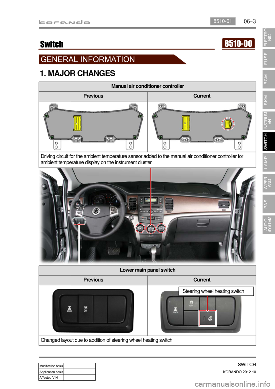
Manual air conditioner controller
Previous Current
Driving circuit for the ambient temperature sensor added to the manual air conditioner controller for
ambient temperature display on the instrument cluster
Lower main panel switch
Previous Current
Changed layout due to addition of steering wheel heating switch
Steering wheel heating switch
Page 731 of 1082

06-20
Temperature dial
In full AUTO mode, the FATC receives various signals
such as the indoor temperature, ambient temperature,
engine coolant temperature, sunlight, from different
sensors to control the A/C compressor, mode door, intake
actuator assembly, air mix door, blower motors, etc. to
keep indoor environments fresh.
Fan speed dial
In full AUTO mode, the blower
motor is controlled
automatically according to the
set temperature. The blower
motor speed can also be
controlled manually.Mode dial
You can choose a desired
mode from the 5 modes by
turning the mode as required.
The dial indicator for the
selected mode comes on to
inform the operator.
Air source mode switch
When you press this switch,
recirculation indicator comes on and
the system is changed into the
recirculation mode. (However, under
defroster
mode or defroster/floor mode, it stays
in the fresh air mode.)
A/C switch
When pressing this switch, the
air conditioner operates in
manual mode and A/C ON
indicator comes on.
The A/C starts automatically
when the defroster mode is
selected.
Page 834 of 1082
01-24
4) Basic Inspection
(1) Horn operation
Listen for the horn sound when pressing the horn pad on the steering wheel. -
(2) Brake operation
Check if there is any abnormal noise, unusually long braking distance, or uneven braking force. If the
brake warning lamp does not go out even after starting the engien or are flashing during driving,
have the brake system checked immediately.
Check the brake pipes and hoses for connection, oil leak, crack or interference after changing the
position of tires. When replacing the tires, check the brake disc for surface condition and wear.
Check the parking brake cable and brake operation. Shorten the checking interval if the parking
brake is used frequently. -
-
-
(3) Exhaust system
Be aware to any changes in sound or smell from the exhaust system. These may be caused by leak or
overheat. Have the exhaust system checked and repaired immediately.
Inspect the exhaust system including catalytic converter. Inspect all the components and body frame
near the exhaust system. -
-
(4) Tires
Unusual vibration of the steering wheel and seats or pulling to one side on the straight and level roads
may indicates the uneven tire inflation pressure or poor wheel balance. -
(5) Steering and suspension system
Inspect the front and rear suspension and the steering system for damage, looseness or missing
parts, signs of wear or lack of lubrication. Inspect the power steering line and the hoses for
connection, leak, crack and chafing. Inspect the drive axle boot and seals for damage, tear or leak.
Replace or repair the system if necessary. -
(6) Engine oil
Check the oil level when the engine is still warm and add the specified engine oil if necessary. -
(7) Coolant
Check the coolant level in the coolant reservoir, coolant conditions (contamination, foreign material),
and hoses for damage and leak. Replace or add the Ssangyong genuine coolant, if needed. -
(8) Engine drive belt
Check all drive belts on the engine for wear, crack and looseness. Retighten or replace the belt, if
needed. -
Page 848 of 1082
02-14
5. TRANSAXLE ELECTRONIC CONTROL SYSTEM
1) General Information
The transmission control unit (TCU) and its input/output network control the following transmission
operations:
Shift timing
Line pressure
Clutch pressure (shift feel)
Torque converter clutch -
-
-
-
also uses these signals when determining transaxle operating strategy. Using all of these input signals,
the TCU can determine when the time and conditions are right for a shift, or when to apply or release the
torque converter clutch. It will also determine the pressure needed to optimise shift feel. To accomplish
this, the TCU operates six variable bleed control solenoids and four on/off solenoids to control transaxle
operation.
2) TCU (Transmission Control Unit)
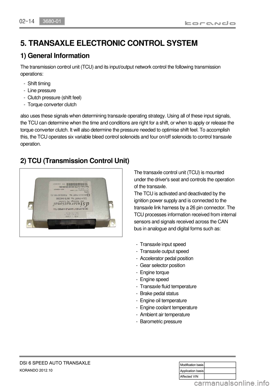
The transaxle control unit (TCU) is mounted
under the driver's seat and controls the operation
of the transaxle.
The TCU is activated and deactivated by the
ignition power supply and is connected to the
transaxle link harness by a 26 pin connector. The
TCU processes information received from internal
sensors and signals received across the CAN
bus in analogue and digital forms such as:
Transaxle input speed
Transaxle output speed
Accelerator pedal position
Gear selector position
Engine torque
Engine speed
Transaxle fluid temperature
Brake pedal status
Engine oil temperature
Engine coolant temperature
Ambient air temperature
Barometric pressure -
-
-
-
-
-
-
-
-
-
-
-
Page 877 of 1082
03-173660-01
5. TRANSAXLE ELECTRONIC CONTROL SYSTEM
1) General Information
The transmission control unit (TCU) and its input/output network control the following transmission
operations:
Shift timing
Line pressure
Clutch pressure (shift feel)
Torque converter clutch -
-
-
-
also uses these signals when determining transaxle operating strategy. Using all of these input signals,
the TCU can determine when the time and conditions are right for a shift, or when to apply or release the
torque converter clutch. It will also determine the pressure needed to optimise shift feel.
2) TCU (Transmission Control Unit)
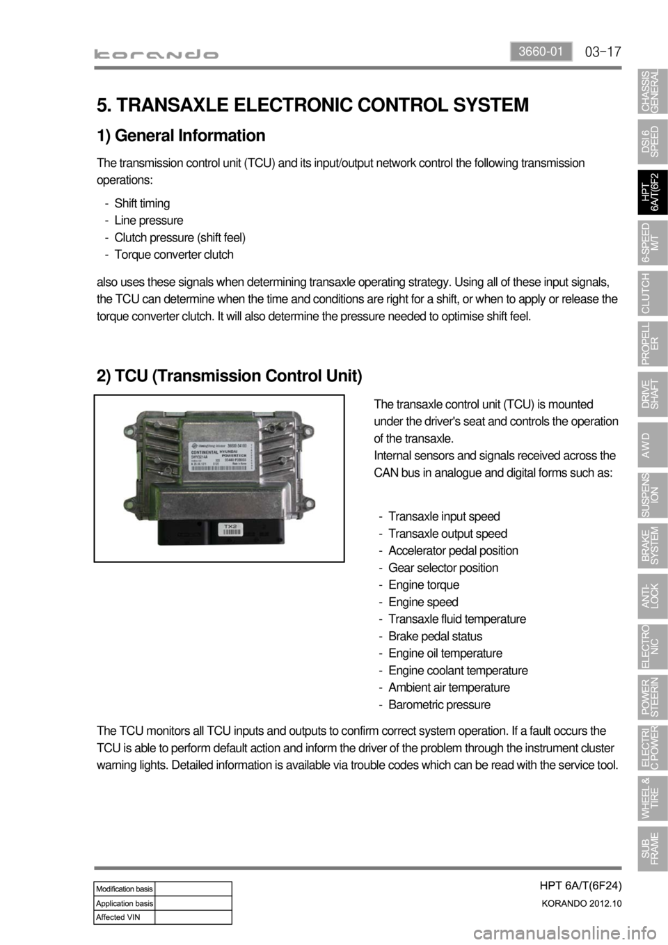
The transaxle control unit (TCU) is mounted
under the driver's seat and controls the operation
of the transaxle.
Internal sensors and signals received across the
CAN bus in analogue and digital forms such as:
Transaxle input speed
Transaxle output speed
Accelerator pedal position
Gear selector position
Engine torque
Engine speed
Transaxle fluid temperature
Brake pedal status
Engine oil temperature
Engine coolant temperature
Ambient air temperature
Barometric pressure -
-
-
-
-
-
-
-
-
-
-
-
The TCU monitors all TCU inputs and outputs to confirm correct system operation. If a fault occurs the
TCU is able to perform default action and inform the driver of the problem through the instrument cluster
warning lights. Detailed information is available via trouble codes which can be read with the service tool.
Page 1006 of 1082

01-56810-00
2) Manual A/C Controller
Manual air conditioner controller
Previous Current
The driving circuit for the ambient temperature sensor is added to the manual air conditioner controller
for ambient temperature display on the instrument cluster.
Connector added
Pin No. Function
B1 -
B2 -
B3 -
B4 Water temp. signal
B5 -
B6 -
B7 -
B8 -
B9 -
B10 Sun-load sensor signal
B11 Ambient temp. sensor signal
B12 -
Page 1010 of 1082

01-96810-00
Incar sensor
This sensor detects the inside temperature and
installed in PCB.Face-Level
(vent mode)Face/Foot-Level
(bi-level mode)Foot-Level
(foot mode)
Foot/Defrost-level
(foot/defrost mode)
Defroster switch
Use this switch to remove for or
ice from the windshield. When
choosing this mode, the airflow
direction will be changed to the
windshield and side glasses, the
air conditioner operates
automatically, and fresh air
comes in. The air flow direction can be controlled by turning the dial. -
Airflow is changed
automatically according to the
setting temperature.
Fan speed dial
Manual control
Fan speed is manually controlled b
y
this dial. The increment is 1℃.
Auto control
Fan speed is automatically
controlled by temperature setting.
The blower motor operates in a
stepless mode. -
-
A/C switch
When pressing this switch,
the air conditioner operates
in manual mode and A/C
ON indicator comes on.
Fan speed dial ▶Mode dial ▶
Page 1013 of 1082

01-12
3. A/C COOLING CYCLE
1) System flow
Condition: Gas/Liquid
Function: Keeps the refrigerant free from moisture by separating/collecting the moisture from it. -
-"Compression -> Condensation -> Expansion -> Evaporation" -
Condition: Liquefied gas/Gas
Function: Cools the air by absorbing the heat from the air around the evaporator. -
-Condition: Liquid/Liquefied gas
Function: Performs adiabatic expansion and flow control for easier evaporation. -
-Condition: Gas/Liquid
Function: Cools and condenses the refrigerant by using ambient air to liquefy it under high pressure. -
-Condition: Gas
Function: Circulates the refrigerant and increases the pressure and temperature for easier
evaporation. -
- 2) Functions
(2) Condenser
(3) Receiver drier
(4) Expansion valve
(5) Evaporator
(1) Compressor
Page 1014 of 1082
01-136810-00
The refrigerant is converted from liquid to gas in the evaporator.
(The refrigerant in the form of fog in the evaporator is vaporized actively)
At this time the refrigerant, in the form of liquid, absorbs the heat in the air which is need for
evaporation (latent heat) and is cooled down. Then the blower blows the cooled air inside the vehicle
to lower the temperature.
There are liquid refrigerant from the expansion valve and evaporated refrigerant in the evaporator.
The evaporation temperature can be predicted from the evaporation pressure (i.e. relationship
between saturation pressure and saturation temperature).
It is important to keep the pressure inside the evaporator low, so that the refrigerant is evaporated at
low temperature to make sure the completely evaporated refrigerant is entered into the compressor. -
-
-
-
- (4) Evaporator (3) Expansion (2) Condensation
The liquid refrigerant lowers the pressure making its evaporation easily accomplished.
This process (lowering the pressure to the level at which evaporation easily takes place before the
liquid refrigerant is sent to the evaporator) is called
"Adiabatic Expansion".
During adiabatic expansion, the expansion valve lowers the pressure of the refrigerant and
determines the correct amount of refrigerant going into the air conditioning evaporator.
That is, the amount of heat, which is needed to stop the evaporation, is determined according to the
cooling load.
The expansion valve detects this and regulates the amount of the refrigerant exactly. -
-
-
-
-The high pressure and high temperature gas (refrigerant) from the compressor is cooled down by
the fresh air entered into the condenser. Then, this gas is converted to liquid and collected in the
receiver drier.
The heat generated from the high pressure refrigerant is dissipated to the ambient air, and it is called
"heat of condensation".
The heat of condensation is the summation of the heat of vaporization (heat that the refrigerant
absorbs from the inside of the vehicle) and the calorific value converted from the amount of work
which is needed to compress. -
- 3) Description for Each Cycle
(1) Compression
The evaporated refrigerant in the evaporator enters to the compressor. And the refrigerant gas is
compressed until it can be liquefied at ambient temperature.
Thus, the low refrigerant pressure is maintained so that the liquid refrigerant can be evaporated
actively at low temperature (around 0℃). -
-