SSANGYONG KORANDO 2012 Service Manual
KORANDO 2012
SSANGYONG
SSANGYONG
https://www.carmanualsonline.info/img/67/57504/w960_57504-0.png
SSANGYONG KORANDO 2012 Service Manual
Trending: inflation pressure, sunroof, hood open, catalytic converter, coolant capacity, ad blue, Gasoline
Page 891 of 1082
03-6
3. MAJOR CHANGES IN MANUAL TRANSAXLE
1) Gear Shift Lever and Cable
Gear shift lever assembly
Old New
The gear shift lever bracket has been changed to adopt the premium console.
Gear shift cable assembly
Old New
The connection and socket to lever has been changed.
Gear shift lever
bracket
Page 892 of 1082
03-73190-01
Front view Rear view
1. OVERVIEW
This vehicle is equipped with WM6F1 M/T (Manual Transmission). This transmission is integrated with an
axle and designed to maximize the driving performance by optimizing the gear ratio according to the
engine torque.
WM6F1 M/T assembly
Page 893 of 1082
03-8
1) Characteristics of WM6F1 M/T
Both Forward and Reverse gears use the helical gear and are made of high-strength material.
Drives the clutch with a concentric slave cylinder mounting bolt.
Shifting the transmission gears is performed through the remote control cable.
A pull type clutch is used for Reverse gear shifting.
Features triple/double/single synchronization. -
-
-
-
-
Clutch housing
Transmission case
Input shaft
Concentric slave cylinder
Shift lever
Selector lever
Wiring bracket
Neutral switch
Backup lamp switch
Reverse idle shaft mounting bolt 1.
2.
3.
4.
5.
6.
7.
8.
9.
10.Control guide bolt
Oil filler plug (for servicing)
Oil drain plug
Oil filler plug (for manufacturing)
Air breather
Detent pin (for securing shift fork)
Oil seal (RH)
Oil seal (LH)
Control housing 11.
12.
13.
14.
15.
16.
17.
18.
19.
Page 894 of 1082
03-93190-01
2) Internal Configuration
Page 895 of 1082
03-10
3) Schematic Diagram
4) Gear Ratio
ItemSpeed gear Final gear
Total gear
ratio Number of
teethGear ratioNumber of
teethGear ratio
Input Output Input Output
1st 13 46 3.538
13 59 4.53816.059
2nd 22 42 1.909 8.664
3rd 28 33 1.179 5.349
4th 43 35 0.814 3.694
5th 38 28 0.737
15 59 3.9332.898
6th 43 27 0.628 2.47
Reverse13 17
3.91 15.377
24 36
One input gear is used for 1st forward driving and back-up driving.
One input gear is used for 4th and 6th forward driving. -
-
Page 896 of 1082
03-113190-01
2. POWER FLOWS
1st speed gear
2nd speed gear3rd speed gear
Sectional view of WM6F1 M/T
Page 897 of 1082
03-12
Reverse gear
4th speed gear5th speed gear
6th speed gear
Page 898 of 1082
03-133190-01
3. SHIFTING MECHANISM
Control shaft Shift lever
Selector lever
5th/6th speed gear shift lug
Reverse gear shift fork
5th/6th speed gear shift fork
5th/6th speed gear & Reverse
shift rail
1st/2nd speed gear shift fork
3rd/4th speed gear shift fork
1st/2nd, 3rd/4th speed gear shift rail 3rd/4th speed
gear shift lug
Page 899 of 1082
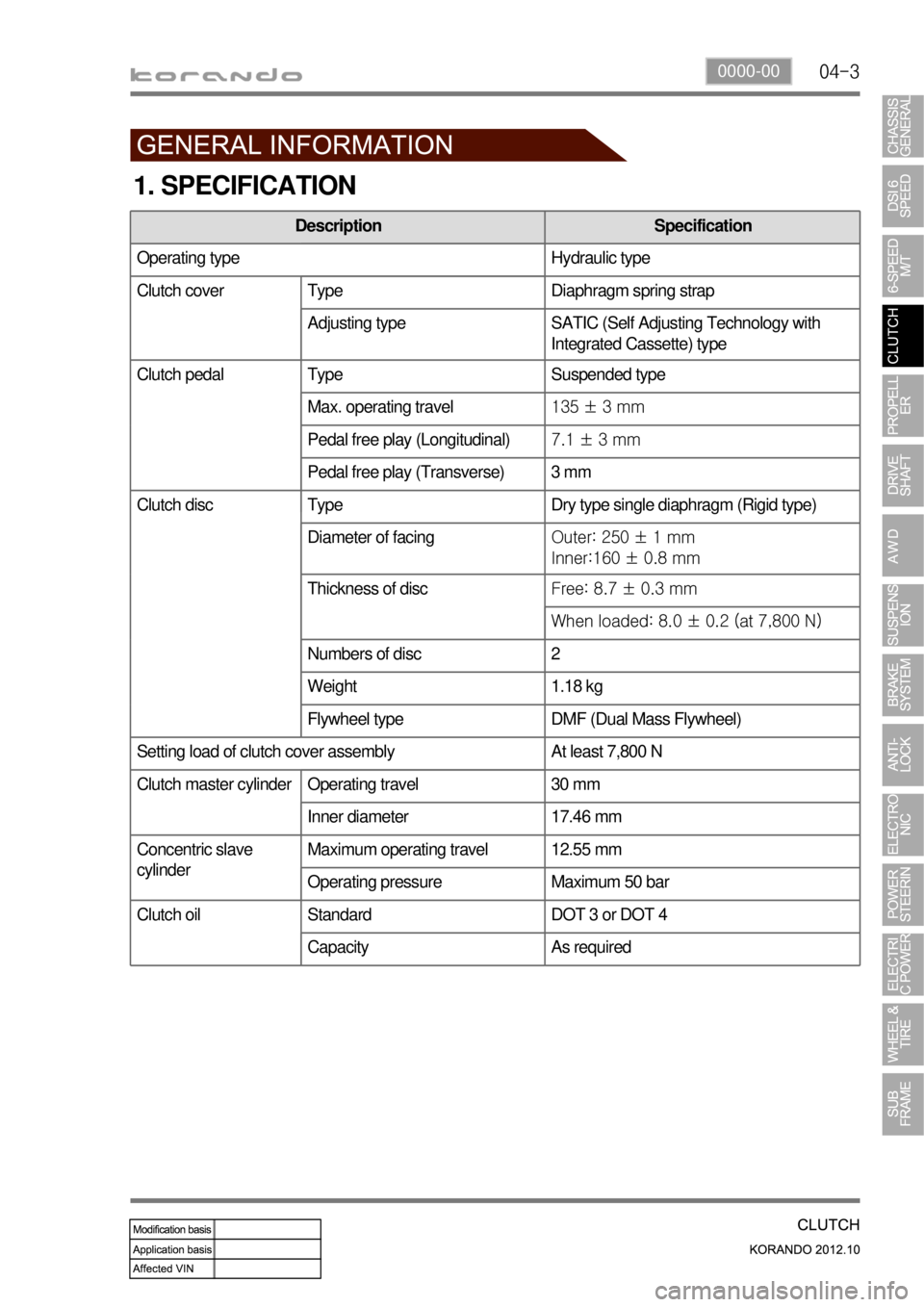
04-30000-00
1. SPECIFICATION
Description Specification
Operating type Hydraulic type
Clutch cover Type Diaphragm spring strap
Adjusting type SATIC (Self Adjusting Technology with
Integrated Cassette) type
Clutch pedal Type Suspended type
Max. operating travel135 ± 3 mm
Pedal free play (Longitudinal)7.1 ± 3 mm
Pedal free play (Transverse) 3 mm
Clutch disc Type Dry type single diaphragm (Rigid type)
Diameter of facingOuter: 250 ± 1 mm
Inner:160 ± 0.8 mm
Thickness of discFree: 8.7 ± 0.3 mm
When loaded: 8.0 ± 0.2 (at 7,800 N)
Numbers of disc 2
Weight 1.18 kg
Flywheel type DMF (Dual Mass Flywheel)
Setting load of clutch cover assembly At least 7,800 N
Clutch master cylinder Operating travel 30 mm
Inner diameter 17.46 mm
Concentric slave
cylinderMaximum operating travel 12.55 mm
Operating pressure Maximum 50 bar
Standard DOT 3 or DOT 4
Capacity As required
Clutch oil
Page 900 of 1082
04-4
2. TIGHTENING TORQUE
DescriptionTightening torque
Amount
Clutch housing boltUpper (17 mm) 85.0 to 100 Nm 2
Front (14 mm)54.0 Nm + 20°1
Rear (14 mm) 51.3 to 56.7 Nm 2
Lower (14 mm) 56.0 to 62.0 Nm 4
Pressure plate assembly bolt (Hexagon 6 mm) 21.0 to 27.0 Nm 6
Concentric slave cylinder bolt (Hexagon 5 mm) 10 to 16 Nm 3
Concentric slave cylinder oil pipe nut 24.5 to 28.4 Nm Remove the nut if it is
necessary. (Once
removed, apply the
Loctite on the thread
before installation.)
Master cylinder nut (12 mm) 7.8 to 17.6 Nm
Master cylinder oil pipe nut (10 mm) 14.7 to 17.6 Nm
Master cylinder push rod lock nut 8.8 to 13.7 Nm
Clutch oil chamber screw and bolt (10 mm) 3.9 to 7.8 Nm
Oil pipe nut (10 mm) 14.7 to 17.6 Nm
Clutch pedal mounting nut (12 mm) 7.8 to 17.6 Nm
Stopper bolt 16 to 22 Nm
Trending: fuse box, fuel pressure, oil filter, wheel bolts, maintenance, automatic trans, clock


