G20df SSANGYONG KORANDO 2012 Service Manual
[x] Cancel search | Manufacturer: SSANGYONG, Model Year: 2012, Model line: KORANDO, Model: SSANGYONG KORANDO 2012Pages: 1082, PDF Size: 96.1 MB
Page 352 of 1082
02-6
3. GUIDELINES ON ENGINE SERVICE
G20DF engine is for FF (Front Engine Front Drive) type vehicle. Therefore, there are some deferent
maintenance and repair works compared to the engine for FR (Front Engine Rear Drive) type vehicle.
For safe and correct works, you must observe the working procedures and instructions in this manual.
And, use the designated tools as follow:
: Power train mounting stand / Engine hanger / Engine stand / Heavy duty engine jack.
Cautions before service works ▶
G20DF engine is FF (Front Engine Front Drive) type engine, and the engine and transmission are
integrated in a same module. Remember that there are many differences compared to
conventional engine in FR (Front Engine Rear Drive) type SUV vehicle.
To remove the engine, use the dedicated equipments such as engine jack, transmission jack,
engine stand and engine crane (1 ton).
To prevent the engine from abruptly starting during service in engine compartment, never allow
anybody to stay in the vehicle.
Make sure to disconnect the negative (-) cable from the battery to prevent any damage to electric
systems.
Make sure to clean the working area and to prepare the necessary tools before service works.
Always place the ignition switch to OFF position if not required. Otherwise, there could be
unexpected damage to electric devices or personal injuries due to short-circuit..
To prevent the foreign material from entering into the fuel injection system, completely seal the
inlets of HP pump, fuel hoses and high pressure pipes.
Do not remove the engine while supporting the oil pan with a jack. -
-
-
-
-
-
-
Lifting up the vehicle ▶
Before lifting up the vehicle with a lift, correctly support the lifting points.
To prevent the vehicle from rolling down, put the chocks under the tires (when using a 4-post lift).
Make sure to support the correct lifting points (when using a 2-post lift). -
-
-
Page 353 of 1082
02-71116-01
Engine and accessories ▶
Engine has a lot of precise components. The specified tightening torque and correct procedures should
be kept during service works. And, the working area is always clean and well prepared.
When disassembling the engine, related parts (bolts, gaskets, etc.) should be stored as a set.
Carefully read the disassembly and reassembly procedures in this manual before starting the
works.
Clean the components completely with engine oil before assembling if needed.
Fully drain the engine oil, coolant and fuel from the vehicle and seal the inlets with the plugs before
removing the engine.
All the interference should be eliminated before removing the engine. -
-
-
-
Tightening the fastener ▶
When reassembling the parts to G20DF, use the angle tightening as a final step.
1. Clean the mating surfaces before tightening.
2. Place the marks with paint to tighten by angle if the angle wrench is not available.Exhaust system ▶
Wear the protective gloves before removing the exhaust pipe.
The exhaust pipe is very hot immediately after stopping th engine. Check if the exhaust pipe is fully
cooled down before servicing the exhaust system. -
-
Cooling system ▶
Scalding hot coolant and steam could be blown out under pressure, which could cause serious
injury. Never remove the coolant reservoir cap when the engine and the radiator are hot. -
The position and direction of the componets is based on the rear view.
Do not tighten the fasteners with excessive force. Especially, the threads of cylinder block could be
damaged.
The self screw bolt makes the thread itself when tightening it. Do not apply excessive force.
Do not reuse the bolt that has been tightened with angle tightening method.
Page 356 of 1082

02-10
2) Hydraulic Tensioner Assembly
The hydraulic tensioner maintains the belt tension to minimize the slip and vibration and provides long
life span of the belt. Hydraulic tensioner consists of hydraulic tension spring, hydraulic damper, lever arm
and tension pulley.
To transfer the tension to the belt from the hydraulic tensioner in small working space in G20DF engine,
the belt system uses the longer lever arm.Overview ▶
Location and Components ▶
Hydraulic tensioner assembly
Components
No Name
1 Tensioner pulley cap
2 Tensioner pulley mounting bolt
3 Tensioner pulley
4 Lever arm
5 Hydraulic tensioner bolt
6 Hydraulic tensioner
Page 369 of 1082
02-231311-01
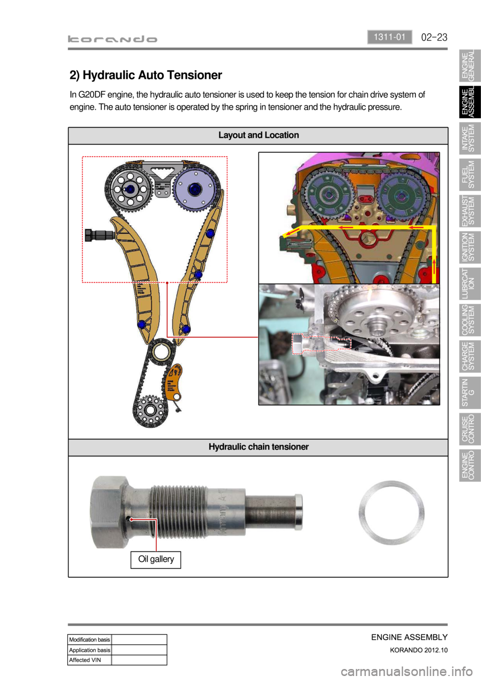
Layout and Location
Hydraulic chain tensioner
In G20DF engine, the hydraulic auto tensioner is used to keep the tension for chain drive system of
engine. The auto tensioner is operated by the spring in tensioner and the hydraulic pressure.
2) Hydraulic Auto Tensioner
Oil gallery
Page 372 of 1082

02-26
Clamping rail
Installed between intake
camshaft sprocket and
crankshaft sprocket
5) Chain Rails
The chain rails are used for optimizing the movement of chain drive system. And they also prevent the
chain from contacting each other when the chain is loose, and reduces the chain wear. The chain rail is
normally made of PA (Polyamide nylon), and PA66 and PA46 are used for the chain rails in G20DF
engine. For the tensioner rail, PA46 is used to provide high anti-wear function and high strength since
the load to the rail is huge. Ther is an open area for shoulder bolt hole in the clamping rail. The chain
rails are installed by shoulder bolts.
Tensioner rail
Installed between
exhaust camshaft
sprocket and crankshaft
sprocket
Page 413 of 1082

06-51443-01
1. OVERVIEW
The ignition system is to supply high voltage generated from the ignition coil to the spark plug. The
G20DF engine is equipped with the independent type direct ignition system that the ignition coil is
installed in each cylinder.
The basic ignition timing in each cylinder is determined by the signals from camshaft position sensor and
crankshaft position sensor.
This ignition system controls the electronic ignition timing received from the engine ECU. To control the
ignition timing precisely, the ECU use the information below:
Engine load
Coolant temperature
Intake air temperature
Engine rpm
Camshaft position sensor (CPS)
Crankshaft position sensor (CKS) -
-
-
-
-
-
If the signal from the camshaft position sensor is not delivered to the engine ECU, the ignition coil and
fuel system cannot be operated.
Page 470 of 1082

15-50000-00
Purge control
solenoid valve
G20DF engine
ECUCoolant Temp
sensorCamshaft position
sensor
Crankshaft position
sensor
T-MAP sensorVIS solenoid valveElectronic throttle
bodyMagnetic trigger
ring
Front oxygen
sensor
Page 472 of 1082
15-70000-00
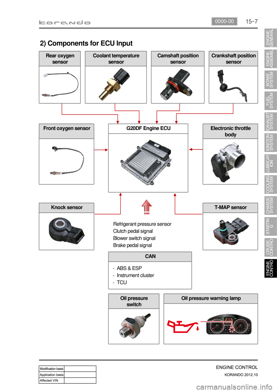
Rear oxygen
sensor
2) Components for ECU Input
Coolant temperature
sensorCamshaft position
sensorCrankshaft position
sensor
Front oxygen sensor
Knock sensor
G20DF Engine ECUElectronic throttle
body
Refrigerant pressure sensor
Clutch pedal signal
Blower switch signal
Brake pedal signal
CAN
ABS & ESP
Instrument cluster
TCU -
-
-
Oil pressure
switchOil pressure warning lamp
T-MAP sensor
Page 473 of 1082
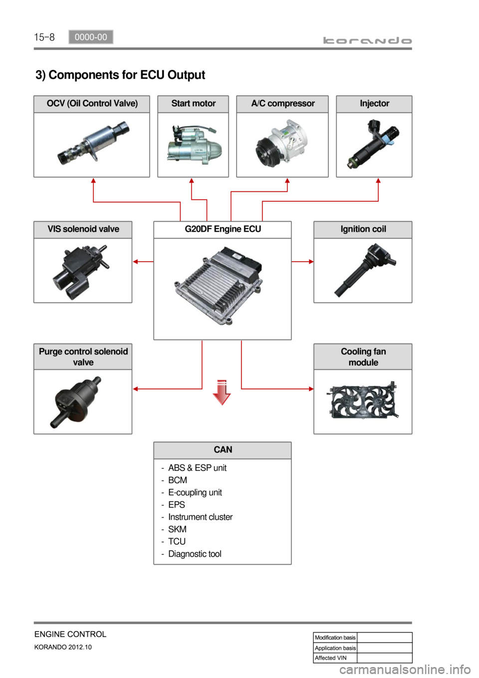
15-8
A/C compressorOCV (Oil Control Valve)
3) Components for ECU Output
Start motorInjector
VIS solenoid valve
Purge control solenoid
valve
G20DF Engine ECUIgnition coil
CAN
ABS & ESP unit
BCM
E-coupling unit
EPS
Instrument cluster
SKM
TCU
Diagnostic tool -
-
-
-
-
-
-
-
Cooling fan
module
Page 478 of 1082

15-130000-00
Coolant temperature
sensor
4) Ignition System Control
(1) Overview
G20DF engine is equipped with the single ignition system. Each spark plug is operated independently
by the ECU and one ignition coil and spark plug are provided for each cylinder.
(2) Components
Input Components ▶
Crankshaft position
sensorAccelerator pedal position
sensor
Knock sensorCamshaft position
sensorElectronic
throttle body
Output Components ▶